
VF Series | Non-Cycling | 10 - 2,000 scfm
DHT Series | High Inlet Temperature | 20 - 125 scfm
AES Series | Energy Saving Digital Scroll | 600 - 10,000 scfm
REFRIGERATED DRYER USER MANUAL
The information in this manual is current as of its publication date and applies to VF, DHT, and AES Series refrigerated air dryers until next revision of this manual.
Copyright © 2017 Aircel, LLC. All rights reserved.
WARRANTY NOTICE
Failure to follow the instructions
and procedures in this manual, or
misuse of this equipment, will void its
warranty.
WARNING!
Users are required to read the entire
User Manual before handling or using
the product. Keep the User Manual in
a safe place for future reference.

| VF, DHT, AES Series Manual
Refrigerated Air Dryer User Manual
ii
DRYER DATA SHEET
Model Number: Serial Number:
Date of Manufacture:
Ship Date: Installation Date:
Customer Address:
Customer City: State/Zip:
Other:

VF, DHT, AES Series Manual |
Refrigerated Air Dryer User Manual
iii
TABLE OF CONTENTS
Section 1: Safety 1
1.1 Introduction 1
1.2 Safety Signal Words 1
1.3 General Safety Procedures 1
1.4 Refrigerant Safety Precautions 1
1.4.1 Inhalation, Skin, & Eye Irritant 1
1.4.2 Refrigerant First Aid Recommendations 2
1.5 Implementation of lockout/tagout 2
1.5.1 Procedures 2
1.5.2 General Security 3
Section 2: Description 4
2.1 Introduction 4
2.2 System 4
2.3 Refrigeration Circuit 4
2.3.1 Types of Refrigerant Used 4
2.4 Compressed Air Circuit 4
2.5 Digital Scroll Compressor 6
Section 3: Installation 7
3.1 Inspection on Arrival 7
3.2 Lifting Information 7
3.3 Installation Codes and Procedures 8
3.4 Locating and Installing the Dryer 8
3.4.1 Air-Cooled Condenser Requirements 9
3.4.2 Cooling Water Requirements 9
3.5 Preliminary Start-Up Checklist 12
3.6 Automatic Drain Valve Adjustments 13
3.7 Zero Loss Condensate Drain 13
Section 4: Operation 14
4.1 Operating Procedures 14
4.2 Short-Term Shut Down 14
4.3 Shut Down Emergency 14
Section 5: Controllers (AES Series) 15
5.1 Home Screen 15
5.2 Status Screen 16
5.3 Information Screen 16
5.4 Alarm Screen 17
5.5 Alarm Log Screen 17
5.6 Diagnostics Screen 18
5.7 Alarm Banner Screen 18
Section 6: Maintenance 19
6.1 Introduction 19
6.2 Maintenance 19
6.2.1 Daily 19
6.2.2 Weekly 19
6.3 Filter Element Replacement 20
Section 7: Troubleshooting 21
7.1 Introduction 21
7.2 Electrical 22
7.3 Refrigeration 22
7.4 Condensate Removal 23
7.5 Other 24
7.6 VF & DHT Series Troubleshooting Guide 25
7.7 AES Series Troubleshooting Guide 30
7.8 AES Series Performance Alert Codes 35
Appendix A: Specifications 36
A.1 Table of Specifications - VF Series 36
A.2 Table of Specifications - DHT Series 37
A.3 Table of Specifications - AES Series 38
Appendix B: Wiring Diagrams 39
B.1 VF Series 39
B.2 DHT Series 42
B.3 AES Series - Air-Cooled Models 45
B.4 AES Series - Water-Cooled Models 52
Appendix C: Material Safety Data Sheets 59
C.1 R-134a 59
C.2 R-404a 66
Service Notes 74
Warranty Information 79


VF, DHT, AES Series Manual |
Refrigerated Air Dryer User Manual
1
1.1 Introduction
To ensure maximum performance and safe operation of an
Aircel refrigerated dryer covered by this manual, everyone
involved with the dryer’s installation, operation, and
maintenance must read and carefully follow the instructions
in this manual.
1.2 Safety Signal Words
Throughout this manual, signal words are present to advise
of safety precautions and/or standard practices. Obey these
signal words as dened below:
DANGER! - Indicates an imminently hazardous situation
which, if not avoided, will result in death or serious injury.
WARNING! - Indicates a potentially hazardous situation
which, if not avoided, could result in death or serious injury.
CAUTION! - Indicates a potentially hazardous situation
which, if not avoided, may result in minor or moderate
injury.
NOTICE - used to address practices not related to personal
injury.
1.3 General Safety Procedures
• Improper installation, operation, or maintenance may
contribute to conditions in the work area or facility that
could result in personal injury and product or property
damage. Check that all equipment is properly selected
and sized for the intended use.
• Consult and comply with national and local codes
relating to fire or explosion and all other appropriate
codes when determining the location and operation of
this equipment.
• Safe and efficient operation of the unit depends on
proper installation.
• Authorities with jurisdiction should be consulted
before installing to verify local codes and installation
procedures. In the absence of such codes, install unit
according to the National Electric Code, NFPA No.
70-latest edition.
• A qualified installation and service agent must complete
installation and service of this equipment.
• DO NOT weld on / to pressure vessel or modify it in any
way.
• DO NOT remove, modify, or adjust protective or safety
devices.
• Lock out power supply and depressurize system before
performing maintenance or service work.
• DO NOT operate the equipment with the control panel
door open.
1.4 Refrigerant Safety Precautions
1.4.1 INHALATION, SKIN, & EYE IRRITANT:
• Use proper safety and protective equipment, including
chemical safety goggles or face shield and impervious
gloves when handling refrigerants.
• Exercise care to ensure that liquid refrigerant does not
come in contact with your skin or eyes.
• DO NOT SMOKE.
• Ventilation in work area must be adequate to keep the
concentration of refrigerant below 1,000 ppm.
SECTION 1: SAFETY
CAUTION!
Misuse / modication hazard
Misuse or modication of this equipment may result
in personal injury.
Do not misuse or modify this equipment under any
conditions.
NOTICE
For optimum performance, use only Aircel replacement
parts.

| VF, DHT, AES Series Manual
Refrigerated Air Dryer User Manual
2
• System must be free of all refrigerant before any welding
or brazing can be performed and must be done in a well
ventilated area.
• Decomposition of refrigerants is hazardous! This material
can be decomposed by high temperatures caused by
an open flame. Hydrofluoric acid and possibly carbonyl
fluoride can form in a liquid or gaseous state. Avoid
exposure to these toxic fumes and irritating materials.
• Leave the work area immediately if you experience any of
the following: smell something unusual, feel light-headed,
experience shortness of breath, feel a tingling sensation
in your fingers or toes, suddenly feel warm or a rapid
heartbeat.
1.4.2 REFRIGERANT FIRST AID RECOMMENDATIONS
1.4.2.1 INHALATION
If high concentrations are inhaled, immediately remove
individual from aected area to an area with a fresh air supply.
Keep individual calm. If not breathing, give articial respiration
or if having diculty breathing, give oxygen and call for
emergency services.
1.4.2.2 SKIN CONTACT
In case of contact with the skin, immediately flush skin with clean
water for at least 15 minutes. Treat for frostbite if necessary by
gently warming affected areas and call for emergency services.
Remove any contaminated clothing or shoes.
1.4.2.3 EYE CONTACT
In case of contact with the eyes, immediately flush eye(s) with
clean water for at least 15 minutes and call for emergency
services.
1.5 Implementation of lockout/tagout
The energy control procedure denes actions necessary to
lockout a power source of any machine to be repaired, serviced,
or set-up, where unexpected motion, or an electrical or other
energy source, would cause personal injury or equipment
damage. The power source on any machine shall be locked
out by each employee doing the work except when motion is
necessary during setup, adjustment, or troubleshooting.
1.5.1 PROCEDURES
The established procedures for the application of energy control
shall cover the following elements and actions and shall be
initiated only be Authorized Persons and done in the following
sequence:
1. Review the equipment or machine to be locked and tagged
out.
2. Alert operator and supervisor of which machine is to be
worked on, and that power and utilities will be turned o.
3. Check to make certain no one is operating the machine
before turning power o.
4. Turn o the equipment using normal shut-down procedure.
5. Disconnect the energy sources:
a. Air and hydraulic lines should be bled, drained, and
cleaned out. There should be no pressure in these lines
or in the reservoir tanks. Lockout or tag lines or valves.
b. Any mechanism under tension or pressure, such as
springs, should be released and locked out or tagged.
c. Block any load or machine part prior to working under it.
d. Electrical circuits should be checked with calibrated
electrical testing equipment and stored energy and
electrical capacitors should be safely discharged.
6. Lockout and/or tag out each energy source using the
proper energy isolating devices and tags. Place lockout
hasp and padlock or tag at the point of power disconnect
where lockout is requried by each person performing work.
Each person shall be provided with their own padlock and
have possession of the only key. If more than one person is
working on a machine, each person shall ax personal lock
and tag using a multi-lock device.
7. Taglock devices shall be used only when power sources
are not capable of being locked out by use of padlocks and

VF, DHT, AES Series Manual |
Refrigerated Air Dryer User Manual
3
lockout hasp devices. The name of the person axing the
tag to power source must be on tag along with date tag was
placed on power source.
8. Release stored energy and bring the equipment to a “zero
mechanical state.”
9. Verify isolation: Before work is started, test equipment to
ensure power is disconnected.
1.5.2 GENERAL SECURITY
1. The lock shall be removed by the Authorized Person who
put the lock on the energy-isolating device. No one other
than the person/persons placing padlocks and lock out
hasps on power shall remove padlock and lockout hasps
and restore power. However, when the authorized person
who applied the lock is unavailable to remove it, her or his
Supervisor may remove padlock(s) and lock out hasp(s) and
restore power only if it is rst:
a. veried that no person will be exposed to danger..
b. veried that the Authorized Person who applied the
device is not in the facility.
c. noted that all reasonable eorts to contact the Authorized
Person have been made to inform her or him that the
lock out or tag out device has been removed.
d. ensured that the Authorized Person is notied of lock
removal before returning to work.
2. Tag out system - Tags are warning devices axed at points
of power disconnect and are not to be removed by anyone
other than the person placing tag on power lockout. Tags
shall never be by-passed, ignored, or otherwise defeated.

| VF, DHT, AES Series Manual
Refrigerated Air Dryer User Manual
4
2.1 Introduction
Refrigerated air dryers are designed to remove moisture
from compressed air by use of mechanical refrigeration
and are used to protect industrial compressed air systems,
machinery, and tools. They are designed to deliver the
required dew point at specified inlet air temperature,
inlet air pressure, inlet flow, and ambient temperature
conditions.
2.2 System
The VFS, DHT, and AES Series refrigerated air dryer
products cover the flow range listed on the manual front
cover and provides reliable dew point performance in
all flow conditions. Through optimization of critical dryer
components – heat exchanger, separator, and condensate
removal – the system ensures the highest performance at
full- and partial load conditions.
Hot saturated air enters the air-to-air heat exchanger of the
refrigerated air dryer and is pre-cooled by the outgoing dry
air. Pre-cooling saves energy by reducing the heat load on
the dryer’s compressor. The cool saturated air enters the
air-to-refrigerant heat exchanger where air temperature is
lowered to the 38 to 42°F range. This dramatic temperature
drop condenses water and oil.
The mixture of cold air and condensation then flows into the
two-stage separator filter where liquids and contaminants
are removed by centrifugal action, directional flow change,
and velocity reduction. Once bulk liquids have been
removed, the compressed air goes through a stainless steel
mist eliminating filter that coalesces oil aerosols and oil
vapors within the 50-micron range, and then separates and
removes them. At this point, the compressed air is dry and
virtually oil-free.
Cold, dry air exits through the pre-cooler heat exchanger
and is reheated by incoming hot air. Reheating restores
energy and also prevents condensation from forming on
the outside of air distribution piping. In the refrigeration
unit, the compressor pumps hot, high-pressure gaseous
refrigerant to the condenser where it is cooled and liquefied
by ambient air. From the condenser, liquid refrigerant first
flows through the receiver, then through a filter/dryer, and
finally through the expansion valve where pressure and
temperature are reduced. This reduction in pressure causes
the liquid refrigerant to boil until it reaches the saturation
temperature that corresponds to its pressure. As the low-
pressure refrigerant passes through the evaporator, heat
flows from the compressed air to the refrigerant, causing
the boiling to continue until all refrigerant is vaporized.
Refrigerant gas is returned to the compressor and the cycle
is repeated.
In the VF and DHT Series dryers, a hot gas by-pass valve is
used to control temperature in the evaporator. In the AES
Series, the Copeland Scroll Digital™ compressor allows the
system to eliminate the need for a hot gas by-pass valve.
The closed loop digital controller continuously monitors the
evaporator temperature and modulates the loading and
unloading of the refrigeration compressor based on current
load conditions.
2.3 Refrigeration Circuit
Refrigerant is cycled through a closed loop system commonly
known as high pressure and low pressure. Refrigerant
is compressed by the compressor to a gas with high
temperature and high pressure, which then travels to the
condenser (air- or water-cooled) to lower the temperature
and condense the gas into a liquid. Liquid travels to the
evaporator (refrigerant-to-air part of the heat exchanger)
and back to the compressor suction side. The process then
repeats. A hot gas by-pass valve is used on the non-cycling
VF Series dryers as a freeze protector in low load conditions
(100 scfm rated models [1/2 Hp] and up).
2.3.1 TYPES OF REFRIGERANT USED
R-134a refrigerant is used in dryer models rated 1200 scfm
and below, while R-404A is used in the VF-1600 and higher.
R-134a is a pure refrigerant providing consistent
performance (zero temperature glide) and easy service (no
mixture of different refrigerants). R-404A is a blend of three
pure refrigerants: 52% R-143A, 44% R-125, and 4% R134A
(by mass). This blend is nearly azeotropic meaning it has a
negligible temperature glide. R404A is well suited to larger
is nearly azeotropic meaning it has a negligible temperature
glide. R404A is well suited to larger equipment as the higher
operating pressures and improved heat transfer properties
allow for smaller condensers, which leads to air dryers with
smaller footprints.
2.4 Compressed Air Circuit
The compressed air dryer circuit uses a patented air-to-air
heat exchanger (VF Series 50 scfm and up, DHT Series 40
scfm and up), and stainless steel brazed plate air-to-air heat
exchanger (AES Series). These heat exchangers act as a pre-
cooler/reheater. Hot, saturated, compressed air first enters
the air-to-air heat exchanger, where it is pre-cooled by
outgoing air from the air-to-refrigerant heat exchanger. This
energy saving heat exchanger provides several advantages,
SECTION 2: DESCRIPTION

VF, DHT, AES Series Manual |
Refrigerated Air Dryer User Manual
5
such as a reduction of the heat load imposed on the refrigerant
compressor and condenser, providing more energy to the
outlet air, and preventing condensation of moisture on the
outside of the plant distribution air line piping. From the air-
to-air heat exchanger, air will enter into the evaporator further
reducing its temperature to a desired pressure dew point.
As the air is cooled, moisture is condensed, separated, and
discharged through the condensate drain. The cooled air then
reenters the air-to-air heat exchanger, in a direction opposite
to the flow of the warm, saturated incoming air. This counter
flow action assures high temperature differential throughout
the heat exchanger, resulting in a more effective heat transfer.
Condenser
Compressor
Expansion Valve
Separator
Pre-Cooler/Re-heater Air to Refrigerant
Drain
Refrigerant
Out
Refrigerant
In
Air In
Air Out
Condenser
Compressor
Drain
Refrigerant Inlet
Air-to-Refrigerant
Heat Exchanger
Air Inlet
Pre-Cooler /
Re-Heater
Separator
Air Outlet
Air-to-Air Heat Exchanger
Stainless Steel Mist Eliminator
Refrigerant Oulet
FIGURE 2-2: TYPICAL SCHEMATIC FLOW DIAGRAM
VF Series 10 - 60; 1,600 - 2,000 scfm rated models
DHT Series 20 scfm rated model
FIGURE 2-3: TYPICAL SCHEMATIC FLOW DIAGRAM
VF Series 75 - 1,000 scfm rated models
DHT Series 40 - 125 scfm rated model
FIGURE 2-1: TYPICAL SCHEMATIC FLOW DIAGRAM
AES Series 600 - 10,000 scfm rated models

| VF, DHT, AES Series Manual
Refrigerated Air Dryer User Manual
6
2.5 Digital Scroll Compressor
Aircel AES Series dryers employ the Copeland Scroll Digital™
compressor to allow consistent dew point performance
while matching load proportionally. The modulation of the
compressor is possible through the unique feature called
axial compliance. This allows the compressor to operate
in two stages – the loaded and unloaded state. AES Series
600 – 1500 scfm models feature an external solenoid valve
that connects the modulation chamber on the top of the
compressor with the suction side. AES Series 1750 and
2000 scfm models, the components are integrated into the
compressor housing. When the solenoid valve is energized,
suction gases causes the top scroll to axially separate. When
the scrolls are separated, the compression of the gas is
interrupted.
When the compressor is unloaded the motor still rotates
at the normal speed, however no work is being performed.
Electrical consumption is reduced to approximately 10% of
full load conditions.
A cycle time is comprised of one loaded state time and
one unloaded state time. The duration of these states is
determined by a closed loop controller, which monitors
the temperature of the evaporator. The controller is set to
have a cycle time of 10 seconds. The percentage of loaded
vs. unloaded determines the capacity of the refrigeration
system. For example, if the loaded state is 5 seconds
and the unloaded state is 5 seconds, the compressor
modulation is equal to 50% output. If the compressor
loaded state time is 8 seconds and the unloaded state is 2
seconds, the compressor modulation is 80%. The capacity
is the time average of the loaded state and the unloaded
state. By varying the states the compressor is able to have
any refrigeration capacity between 10% and 100%.
100
90
80
70
60
50
40
30
20
10
0
0 10 20 30 40 50 60 70 80 90 100
Air Load %
Energy Consumption %
Key
AES Series
Non-Cycling
FIGURE 2-4: Graphic of Digital Scroll Operation. The top
view shows the compressor loaded with compression taking
place. The bottom view shows the scrolls separated and no
compression taking place.
FIGURE 2-5: Energy Consumption vs Inlet Load. Graph shows
difference in energy consumption between general, non-cycling
refrigerated air dryers and AES Series Energy Saving, Digital
Scroll refrigerated air dryers.

VF, DHT, AES Series Manual |
Refrigerated Air Dryer User Manual
7
3.1 Inspection on Arrival
All non-cycling refrigerated air dryers are tested and operated
before shipment. However, shipping stresses have the potential
to cause damage to the unit. To ensure smooth installation, it
is recommended that immediately upon receipt of the unit, the
system is checked for the following:
1. Report any damage to the delivery carrier.
2. Request a written inspection report from the Claims
Inspector to substantiate the claim.
3. File claims with the delivery carrier.
4. Compare unit received with description of product ordered.
Check the serial plate label and make sure that it is the
correct Model was ordered. Note the equipment Capacity
and Power Supply requirements and ensure that they are in
accordance with your specifications. The rated conditions
of the dryer are indicated on the serial plate label. If there
is any discrepancy, contact your representative listed on
the manual back cover.
5. Shipping stresses can loosen connections. All pipe and
tubing connections should be inspected.
6. Observe pressure of refrigerant suctions gauge to
determine if refrigerant has leaked during transit. If the
gauge reading does not match that mentioned on the
serial plate label, immediately contact Technical Support
listed on the manual back cover.
7. Report incomplete shipments to the delivery carrier and
your service representative.
3.2 Lifting Information
1. Use all lifting points provided. Special care must be used
when lifting the dryer to prevent tip-over.
2. Use clevis connectors, not hooks, on lifting slings.
3. Only lift unit under support frame/base by using the fork
lift openings provided. Do not lift by piping.
4. Check the approximate weight provided on the specification
control drawing to ensure adequate lift truck capacity.
5. Allow only qualified operators to lift the equipment.
6. Refer to applicable OSHA regulations and local codes when
using cranes, forklifts, and other lifting equipment.
SECTION 3: INSTALLATION
WARNING!
Lifting Hazard
Failure to lift the unit correctly can result in severe
personal injury or property damage.
• Use appropriate lifting equipment and adopt
all safety precautions needed for moving and
handling the equipment.
• A hand cart, forklift, or crane is recommended for
unloading and installation.
• Lift unit by lifting lugs and frame only. Do not lift
by piping.

| VF, DHT, AES Series Manual
Refrigerated Air Dryer User Manual
8
3.3 Installation Codes and Procedures
• Safe and efficient operation of the unit depends on proper
installation.
• Authorities with jurisdiction should be consulted before
installing to verify local codes and installation procedures.
In the absence of such codes, install unit according to the
National Electric Code and NFPA No. 70-latest edition.
• A qualified installation and service agent versed in all
regulatory codes must complete installation of this unit.
3.4 Locating and Installing the Dryer
1. Locate unit on a level foundation. Dryer should be mounted
on a suitably structured flat and level floor or base that is
free from vibration.
2. Install unit to provide adequate clearance for maintenance
services. Dryer and accompanying filters should be installed
with at least 2 to 5 feet clearance from the adjoining walls
to provide easy access for routine maintenance and
adequate air flow across the condensing coil.
3. The frame or cabinet must be securely bolted to the
foundation to prevent movement resulting from earth
tremors and induced piping vibration.
4. Install unit using the correct pipe size and pressure rating.
See drawing package provided with the unit. Connect the
inlet of the dryer to the moist gas from the inlet filter.
Install the inlet piping and the inlet shutoff valve. Install the
outlet piping and the outlet shutoff valve (a union with a
valve by-pass can be installed at the inlet and outlet valves
to accommodate isolation of the dryer for maintenance).
Compressed air piping has to be at least the same size as
that of the inlet and outlet connections of the dryer. Larger
pipe sizes can be used with appropriately rated reducers.
5. Optional system configuration: Install a dryer bypass or
isolation valve to allow isolation of the dryer for service and
maintenance without interrupting the compressed air flow.
6. Minimum recommended filtration: Install an Aircel inline
compressed air particulate pre-filter before the dryer to
protect it against dirt and possible clogging of the heat
exchanger.
7. Additional recommended filtration: Install an Aircel inline
compressed air coalescing after filter after the dryer.
8. Provide adequate power supply. See Section A: Specifications.
Make all electrical connections to the dryer as shown on the
wiring diagram. Special care must be taken in connecting
the proper voltage as indicated on the specification sheet
and wiring schematic. Three phase units are equipped with
a phase monitor, which will prevent unit from operating
when wired in reverse. It is mandatory that the dryer be
grounded. Use of your plant’s frame as a ground may
cause problems with the controls. A fused disconnect is
not supplied with this equipment; therefore, one must be
supplied by customer. All electrical fuses, breakers, etc.
WARNING!
Electric Shock Hazard
This machine is connected to high-voltage power,
which can cause severe electrical shock and injury.
• Follow proper lock out/tag out procedures before
performing service or maintenance work.
• Electrical installation must be performed by a
qualied electrician and comply with all applicable
national and local codes.
WARNING!
Inappropriate tools hazard
Using inappropriate tools for installation or
maintenance work can lead to personal injury or
property damage.
Appropriate tools must be used for all installation and
matinenance work.
WARNING!
Pressure and temperature hazards
Operation at elevated pressure or temperature
may cause damage to the dryer or serious injury to
personnel.
Each dryer is checked at the factory for proper
operation at the conditions noted on the serial plate
label.

VF, DHT, AES Series Manual |
Refrigerated Air Dryer User Manual
9
should be sized by a qualified electrician and comply with
all applicable national and local codes. Our company is
not liable for any code violations, component damage,
downtime or consequential damage related to customer
supplied electrical components and connections.
9. The ambient temperature should be between 40 °F and
100 °F. Low temperature could affect the dryer process
and result in high outlet dew point. In conditions where
the ambient drops below freezing, it is recommended that
a heat trace be used for the equipment. This will ensure
trouble-free operation during the winter months (the dew
point of the outlet air will be consistent).
• In some cases, a head pressure control valve may be
needed. (Optional)
10. Do not place the system in service until the above steps
have been completed and that all ratings and specifications
have been verified to match the requirements in the
drawing package supplied with the unit.
11. If there are any changes in the operating conditions of
the system from those published in this manual, contact
Technical Support.
3.4.1 AIR-COOLED CONDENSER REQUIREMENTS
Cooling air must be drawn from a clean source to reduce dust
and dirt accumulation on the condenser coils. Air temperature
should not exceed 100°F (38°C).
3.4.2 COOLING WATER REQUIREMENTS (WATER-
COOLED CONDENSING UNITS)
Cooling water is required for water-cooled refrigerant
condensers (scfm rated model 100 and up). The user is
responsible for piping the water to and from the condenser.
The required water flow rate depends on the water
temperature. A water-regulating valve (supplied with the dryer)
automatically adjusts the flow to compensate for variation in
water temperature, water pressure, and dryer air load. The
table below indicates the amount of cooling water required
in gallons per minute (gpm) at given incoming temperatures
for the condenser Hp size in each model. The refrigerant
discharge pressure control will shut down the refrigerant
compressor if cooling is inadequate.
NOTICE:
• Water cooled condensers are pre-set at the factory for city
water usage.
• Water regulating valve may need to be adjusted to other
water supply conditions. Contact technical support for
assistance.
• Minimum water pressure is 25 psig for city water and 35
psig for tower water. Cooling water pressures less than
these minimums may reduce dryer drying capacity.
• Maximum water pressure is 125 – 150 psig.
• Water flow rate requirements must be increased by 10%
for seawater cooled condensers (Assuming 3.5% salinity
at 77°F.
Drain
Valve
Air or Water
Cooled
Condenser
Air
Compressor
Drain
Valve
Dry Air
to Plant
Drain
Valve
Refrigerated Dryer
After Filter
Pre-Filter
Wet Receiver
(optional)
Dry Receiver
(optional)
Separator
Drain
Valve
FIGURE 3-1: Typical Installation Setup

| VF, DHT, AES Series Manual
Refrigerated Air Dryer User Manual
10
Model by SCFM
Rating Refrigeration HP
Cooling Air Flow
(cfm)
10, 15, 25 0.20 275
40, 50 0.25 300
60, 75 0.33 300
100 0.50 350
125, 150 0.75 525
200 1.25 750
250, 300 1.50 1,250
400 2 3,000
500, 600 3.50 3,000
800, 1000 5 5,000
1,200 6 5,000
1,600 7 6,000
2,000 10 6,000
Model by SCFM
Rating Refrigeration HP
Cooling Air Flow
(cfm)
20 0.33 300
40 0.50 350
50 0.50 350
75 0.75 525
100 0.75 525
125 1.25 750
TABLE 3-1: Air-Cooled Cooling Air Flow -
VF Series
TABLE 3-2: Air-Cooled Cooling Air Flow -
DHT Series
TABLE 3-3: Air-Cooled Cooling Air Flow -
AES Series
Model by SCFM
Rating Refrigeration HP
Cooling Air Flow
(cfm)
600 3.0 3,000
800 4.0 4,500
1,000 5.0 5,000
1,250 6.0 5,000
1,500 7.5 5,500
1,750 & 2,000 10.0 6,000
*Requirements are per module

VF, DHT, AES Series Manual |
Refrigerated Air Dryer User Manual
11
Incoming Water Flow Rate Requirements
(in gpm at dierent inlet water temperature)
Model by SCFM
Rating Condenser HP 70°F 80°F 85°F 90°F
100 0.50 1.50 1.75 2 C/F
125, 150 0.75 2.50 2.75 3 C/F
200 1.25 2.50 2.75 3 C/F
250, 300 1.50 4 4.50 5 C/F
400 2 5 5.50 6 C/F
500, 600 3.50 8 9 10 C/F
800 5 8 9 10 C/F
1,000 5 13 14.50 16 C/F
1,200 6 14 16 18 C/F
1,600 7 18 20 22 C/F
2,000 10 26 29 32 C/F
TABLE 3-4: Water-Cooled Water Flow Requirements- VF Series
TABLE 3-5: Water-Cooled Water Flow Requirements- DHT Series
Incoming Water Flow Rate Requirements
(in gpm at dierent inlet water temperature)
Model by SCFM
Rating Condenser HP 70°F 80°F 85°F 90°F
40,50 0.50 1.50 1.75 2 C/F
75,100 0.75 2.50 2.75 3 C/F
125 1.25 2.50 2.75 3 C/F

| VF, DHT, AES Series Manual
Refrigerated Air Dryer User Manual
12
3.5 Preliminary Start-Up Checklist
1. Check that the inlet and outlet connections are the correct
size and pressure rating, and tightened securely.
2. Check that the correct power supply is connected to the
non-cycling refrigerated air dryer system with an adequate
disconnect switch.
3. Check that all compressed air line service valves are open
and that compressed air is available to be supplied to the
non-cycling refrigerated air dryer system.
4. Check that all liquid drain service valves are open. This is
to ensure that any residual bulk condensate that may have
accumulated in the compressed air lines is discharged
immediately upon start up. These drains must be closed
once system is brought on line for use. The drain valve on
the refrigerated air dryer can be opened by pushing the
test button located on the drain body.
5. With the customer-supplied compressed air to the system,
OPEN the inlet valve slowly to gradually pressurize the
system. Do not open valve too quickly. Opening valve and
suddenly pressurizing the system can cause damage to the
dryer heat exchanger and other components.
6. Check the air system piping connections and dryer system
connections for leaks at this time. Repair and retest any
leaks.
7. Verify that all instrumentation (pressure gauge/s) and
drain air tubing fittings are tight.
Incoming Water Flow Rate Requirements
(in gpm at dierent inlet water temperature)
Model by SCFM
Rating Condenser HP 70°F 80°F 85°F 90°F
600 3.0 8 9 10 C/F
800 4 8 9 10 C/F
1,000 5 13 14.5 16 C/F
1,250 6 14 16 18 C/F
1,500 7.5 18 20 22 C/F
1,750 & 2,000 10 26 29 32 C/F
TABLE 3-6: Water-Cooled Water Flow Requirements- AES Series
*Requirements are per module
C/F: Consult Factory
NOTICE
• For single-phase models, wait at least six (6) hours
after transporting or moving of dryer system
before starting the dryers. Turn the main power
switch to the dryer on, but do not turn the dryer
on/o switch to the on position until six (6) hours
have passed.
• For three-phase models, ensure that the power
switch is in the “o” position, but the electrical
service to the dryer is energized. This dryer must
be in this mode for at least twelve (12) hours
to allow the compressor crankcase heater to
energize and evaporate any liquid refrigerant
from the compressor. After twelve (12) hours,
turn on the power switch of the dryer. The power
indicating light should turn on.

VF, DHT, AES Series Manual |
Refrigerated Air Dryer User Manual
13
8. Ensure that the air system has come up to full pressure and
has filled the dryer with compressed air. Before opening
the outlet valve on the system and after the dryer has been
started under no load, let the dryer run for at least fifteen
(15) minutes to allow stabilization of the system. Verify the
following:
a. The dryer is designed to run continually and should
not be cycling on and off with the air compressor. The
non-cycling operation of the dryer is controlled by an
automatic expansion valve or a thermostatic expansion
valve / hot gas by-pass valve. The valves will open and
close automatically depending on the of heat load to
the evaporator, thus maintaining the desired pressure
dew point.
b. Check the inlet compressed air temperature and
pressure to the dryer and verify that it meets the
specified requirements.
c. Fan rotation, for dryers with an air-cooled condenser,
rotation should be in accordance with the fan rotation
shown on the details located on top and back of the
condenser. Cooling air is drawn through the condenser
coils. Three phase units are equipped with three phase
monitors, which will prevent the fan(s) and compressor
from running backwards. The unit will not turn on
unless the wire leads are in the correct location. The
phase monitor, located in the electrical box, will display
a green light, when the unit is phased properly. A red
light indicates that the unit is not phased properly. If the
motor rotation is not correct, turn off the power switch
and put the main power supply disconnect in the “off”
position; lock and tag; check the wiring; correct the wire
lead locations; recheck for correct phasing.
d. The refrigeration gauge readings should be as follows:
• Refrigerant suction pressure
R-134a = 28-40 psig
R-404a = 75-90 psig
• Refrigerant discharge pressure
R-134a = 160-230 psig
R-404a = 290-400 psig
9. After the preliminary start up checklist has been completed,
the compressed air outlet valve on the dryer system can
now be slowly opened to supply clean dry compressed air
to the facility.
10. After start-up and approximately one month of service,
check that all piping and fittings are tight and free of leaks.
3.6 Automatic Drain Valve Adjustments
The automatic drain valve supplied is standard on the separator
and should open regularly and discharge any accumulated
water into the drain line. The period between openings varies
with the dryer and operating conditions (electronic type). To
minimize air losses, the timer should be adjusted to open the
drain solenoid just long enough to discharge the accumulated
condensate. The factory sets the automatic drains to open for
7 seconds about every 7 minutes. If more than two seconds
of dry air comes out at the end of every discharge cycle,
reduce the open time (seconds) or increase the interval of the
discharge (minutes) to minimize air loss. If liquid is still being
discharged when the discharge cycle stops, increase the open
time (seconds) or shorten the interval of discharges (minutes)
so it discharges more often.
3.7 Zero Loss Condensate Drain
Aircel AES dryers are supplied with zero air loss condensate
drains standard on the separator and after the evaporator.
These drains should be checked regularly via the test
function to verify proper operation. The period between
openings varies with the operating conditions of the dryer.
The capacitive level sensing technology allows a direct acting
valve to discharge condensate without losing compressed air.
Unlike timer drains, these drains do not need to be adjusted.
The drain is equipped with an alarm feature. The alarm will
activate if the valve opens too many consecutive times without
a pause. If the alarm is activated check to see if debris is
blocking the valve or outlet.
NOTICE
The above discharge pressure depend upon ambient
temperature and can vary slightly according to
temperature uctuations.
NOTICE
• Models with the hot gas by-pass valves and
expansion valves are preset at the factory for
the desired dew point. Do not adjust without
consulting with the factory.*
• The dryers are fully automatic and do not require
any auxiliary controls.
* Adjustments not authorized by the factory may void the
warranty.

| VF, DHT, AES Series Manual
Refrigerated Air Dryer User Manual
14
4.1 Operating Procedures
After the initial startup, the dryer operation is completely
automatic. To understand the details of the operation, see
Figure 2-1: Typical Schematic Flow Chart on page 4.
4.2 Short-Term Shut Down
(Over Night or Weekends)
The refrigerated air dryer system can be shut down at any time
by turning the unit off at the dryer by using the on/off switch or
at the main disconnect switch.
4.3 Shut Down Emergency
The non-cycling refrigerated air dryer system can be shut down
under any conditions and at any time by turning the unit off
at the dryer or at the main disconnect switch. Once power is
removed from the dryer system, the dryer must be isolated
from the compressed air stream to avoid a refrigeration circuit
over pressure situation.
SECTION 4: OPERATION
WARNING!
Pressure Hazard
This machine contains contents under high pressure,
which can cause severe injury.
• To avoid possible hazard or injury, the operator
should be fully familiar with the refrigerated air
dryer system and its operation.
• When the system is shutdown and power removed,
lock out power supply and depressurize system
before performing maintenance or service work to
avoid injury to personnel or property damage.
NOTICE
Before running compressed air ow through the dryer,
run the dryer for 15 minutes to stabilize temperature.

VF, DHT, AES Series Manual |
Refrigerated Air Dryer User Manual
15
SECTION 5: CONTROLLERS (AES SERIES)
5.1 Home Screen
The main screen allows the user to view critical operating
conditions of the unit: suction and discharge pressures.
suction and discharge temperatures, dryer load, compressor
off/on status, fans off/on status, unloader off/on status as
well as navigation to the other screens. The functions are as
follows:
• STATUS SCREEN: Navigates to the status screen
• INFO SCREEN: Navigates to the info screen
• ALARM SCREEN: Navigates to the alarm status screen
• ALARM LOG: Navigates to the alarm log screen
• SUCTION PSI: Shows the suction pressure of the unit
• SUCTION °F: Shows the suction temperature of the unit
• DISCHARGE PSI: Shows the discharge pressure of the unit
• DISCHARGE °F: Shows the discharge temperature of the
unit
• DRYER LOAD %: Shows the percentage of the dryer load
• COMPRESSOR OFF/ON: Indicates whether the compressor
is off or on. Green indicates ON.
• FAN 1 OFF/ON: Indicates whether fan 1 is off or on. Green
indicates ON.
• FAN 2 OFF/ON: Indicates whether fan 2 is off or on. Green
indicates OFF.
• UNLOADER OFF/ON: Indicates whether the unloader is off
or on. Green indicates ON.
• NO ALARM: Displays the alarm indication. When NO
ALARM is indicated, the unit is in working order. When
an alarm is active, the indication will be red and will
read COMMON ALARM. To see which alarms are active,
navigate to the ALARM SCREEN. To view when the alarm
occurred, navigate to the ALARM LOG.
FIGURE 5-1: Home Screen
| VF, DHT, AES Series Manual
Refrigerated Air Dryer User Manual
16
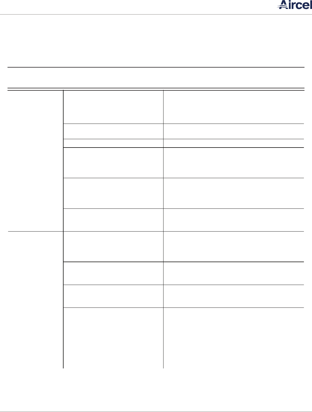
5.3 Information Screen
The information screen gives alarm information from the
Performance Alert module located in the condensing unit
electrical enclosure. The Performance Alert module will flash
a yellow light to indicate certain alarms (for example: the light
will flash twice for a system trip alarm)
• MAIN SCREEN: Navigates to the main screen
• INFO SCREEN: Navigates to the info screen
• ALARM SCREEN: Navigates to the alarm status screen
• ALARM LOG: Navigates to the alarm log screen
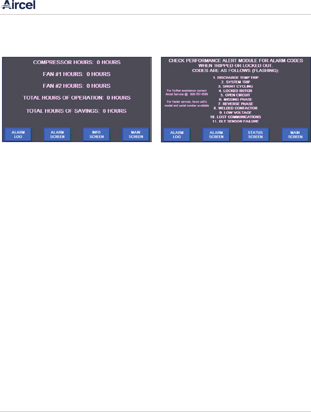
5.2 Status Screen
The status screen shows the user the compressor hours of
operation, fan hours of operation, total hours of operation,
and total savings hours.
• MAIN SCREEN: Navigates to the main screen
• INFO SCREEN: Navigates to the info screen
• ALARM SCREEN: Navigates to the alarm status screen
• ALARM LOG: Navigates to the alarm log screen
FIGURE 5-2: Status Screen FIGURE 5-3: Information Screen

VF, DHT, AES Series Manual |
Refrigerated Air Dryer User Manual
17
5.4 Alarm Screen
The alarm screen shows the status of each alarm. Green
indicates no alarm and red will indicate a failure.
• MAIN SCREEN: Navigates to the main screen
• INFO SCREEN: Navigates to the info screen
• ALARM SCREEN: Navigates to the alarm status screen
• ALARM LOG: Navigates to the alarm log screen
• GOTO HMI CONFIG: Navigates to the configuration menu
of the HMI. It is not recommended to press this button
unless otherwise instructed by Aircel Service. If pressed,
the user can return to the running screens by navigating
to the file manager button and pressing the run button
with the AES_STD program highlighted.
5.5 Alarm Log Screen
The alarm screen shows the status of each alarm. Green
indicates no alarm and red will indicate a failure.
• MAIN SCREEN: Navigates to the main screen
• INFO SCREEN: Navigates to the info screen
• ALARM SCREEN: Navigates to the alarm status screen
• ALARM LOG: Navigates to the alarm log screen
• GOTO HMI CONFIG: Navigates to the configuration menu
of the HMI. It is not recommended to press this button
unless otherwise instructed by Aircel Service. If pressed,
the user can return to the running screens by navigating
to the file manager button and pressing the run button
with the AES_STD program highlighted.
FIGURE 5-4: Alarm Screen FIGURE 5-5: Alarm Log Screen

| VF, DHT, AES Series Manual
Refrigerated Air Dryer User Manual
18
5.7 Alarm Banner Screen
The alarm banner pops up anytime there is an actual alarm in
the PLC. The alarm banner will show the last alarm given. If
there are multiple alarms, the next alarm given will be shown
as each alarm is cleared.
• MAIN SCREEN: Navigates to the main screen
• INFO SCREEN: Navigates to the info screen
• ALARM LOG: Navigates to the alarm log screen
• CLEAR LIST: Clears the alarm log
• Up Arrow: Scrolls up through the logs
• Down Arrow: Scrolls down through the logs
5.6 Diagnostics Screen
The diagnostics screen will pop up if there is a communcations
error between the PLC and HMI, or if there is a major fault
(error) of the HMI itself.
FIGURE 5-6: Diagnostics Screen FIGURE 5-7: Alarm Banner Screen

VF, DHT, AES Series Manual |
Refrigerated Air Dryer User Manual
19
6.1 Introduction
To reach a field service technician or for technical support,
please call the number on the manual back cover.
6.2 Maintenance
Refrigerated air dryers require very little maintenance for
satisfactory operation. Optimum performance can be expected
if the following routine maintenance steps are taken.
6.2.1 DAILY
With the dryer on-line:
• Verify the operating pressure, temperature, and flow rate
are correct and conform to those listed in the Design
Parameters section. Adjust system if required.
• Always check refrigerant gauges to insure refrigeration
system is working properly.
• Check condensate drain separator for proper condensate
discharge. If no discharge is evident then depressurize
the unit, dismantle and clean separator and/or drain line.
Proper drain trap maintenance is the owner’s responsibility.
It is not covered by warranty.
• Make certain airflow is directed through dryer only. Observe
by-pass valves proper positions.
6.2.2 WEEKLY
• Repeat all daily inspections and record data in the
maintenance log.
To reach a field service technician or for technical support, please call the number on the manual back cover.
SECTION 6: MAINTENANCE
WARNING!
Electric Shock Hazard
This machine is connected to high voltage power,
which can cause severe electrical shock and injury.
• Follow proper lock out/tag out procedures before
performing service or maintenance work.
• Prior to performing any maintenance on the dryer,
all personnel are strongly advised to familiarize
themselves with the equipment by reading the
entire contents of this operation manual.
• Follow all safety procedures prior to performing
any maintenance activity on the dryer.
WARNING!
Pressure Hazard
This machine contains contents under high pressure,
which can cause severe injury.
• To avoid possible hazard or injury, the operator
should be fully familiar with the refrigerated dryer
system and its operation.
• When the system is shutdown and power removed,
lock out power supply and depressurize system
before performing maintenance or service work
to avoid injury to personnel or property damage.
CAUTION
Inappropriate Tools Hazard
Using inappropriate tools for installation or
maintenance work can lead to personal injury or
property damage.
Appropriate tools must be used for all installation and
maintenance work.

| VF, DHT, AES Series Manual
Refrigerated Air Dryer User Manual
20
• Clean the condenser coils of accumulated dust and dirt with
a soft brush and/or with air pressure from a compressed
air nozzle (maximum 100 psig).
• Check the gauge readings for optimum system operation.
• Check oil removal filter (coalescer) indicator (if applicable);
if it is red, replace the filter.
6.3 Filter Element Replacement
1. Depressurize the air system to release the compressed air
from the air dryer.
2. Remove the filter bowl by turning the bowl 1/4 turn counter
clockwise, be sure the O-ring is in place on the top half of
the oil filter housing and that the O-ring seats properly. Air
leaks may occur if the O-ring is not secured (important).
3. The same procedure applies when removing the filter
separator for changing the element (if applicable).
NOTICE
Shutting down the air compressor will not depressurize
the air dryer unit. Close air line valves before and after
dryer and then depressurize unit. Depressurize dryer
by pushing the test button on the dryer system drain
until there is no more pressure in the dryer system.

VF, DHT, AES Series Manual |
Refrigerated Air Dryer User Manual
21
SECTION 7: TROUBLESHOOTING
7.1 Introduction
If there is a problem with the refrigerated air dryer or
contamination down stream is present, the problem may be
identified from one or more of the following sources:
• Electrical
• Refrigeration
• Condensate removal (drains)
• Other
Do not assume these are the only problems that may occur. All
available data concerning a problem should be systematically
analyzed before undertaking any repairs or component
replacement procedures.
WARNING!
Electric Shock Hazard
This machine is connected to high voltage power,
which can cause severe electrical shock and injury.
• Follow proper lock out/tag out procedures before
performing service or maintenance work.
• Prior to performing any maintenance on the dryer,
all personnel are strongly advised to familiarize
themselves with the equipment by reading the
entire contents of this operation manual.
• Follow all safety procedures prior to performing
any maintenance activity on the dryer.
WARNING!
Pressure Hazard
This machine contains contents under high pressure,
which can cause severe injury.
• To avoid possible hazard or injury, the operator
should be fully familiar with the refrigerated dryer
system and its operation.
• When the system is shutdown and power removed,
lock out power supply and depressurize system
before performing maintenance or service work
to avoid injury to personnel or property damage.
CAUTION
Inappropriate Tools Hazard
Using inappropriate tools for installation or
maintenance work can lead to personal injury or
property damage.
Appropriate tools must be used for all installation and
maintenance work.

| VF, DHT, AES Series Manual
Refrigerated Air Dryer User Manual
22
7.2 Electrical
• Make certain that the dryer is connected to proper power
supply in accordance with electrical diagram provided.
• Check electrical breaker, fuse, or disconnect to determine
if there is electrical power to the unit.
• A quick check should determine if the power switch is
turned on and the unit is running.
• After determining that power is supplied to the unit, go to
the next step.
7.3 Refrigeration
Non-cycling refrigerated air dryers with R-134a refrigerant
should have a suction gauge pressure reading of 28-40 psig
and a discharge gauge pressure reading of 160-250 psig
with the unit in the on position under full or partial load. If
the refrigerant gauge(s) reads more or less than the above
specified pressures, troubleshoot items below.
1. High refrigerant readings generally indicate:
• Dirty condenser - Clean immediately!
• Dryer not turned on.
• Overloading - Airflow or conditions in excess of dryer
capacity.
• High ambient temperature (≥ 100°F) Provide adequate
WARNING!
Electric Shock Hazard
This machine is connected to high voltage power,
which can cause severe electrical shock and injury.
• Follow proper lock out/tag out procedures before
performing service or maintenance work.
• Prior to performing any maintenance on the dryer,
all personnel are strongly advised to familiarize
themselves with the equipment by reading the
entire contents of this operation manual.
• Follow all safety procedures prior to performing
any maintenance activity on the dryer.
WARNING!
Electric Shock Hazard
This machine is connected to high voltage power,
which can cause severe electrical shock and injury.
Follow proper lock out/tag out procedures before
performing service or maintenance work.
WARNING!
Chemical Hazard
Improper handling of refrigerant can cause severe
injury.
Refrigerant handling must be performed by a qualied
technician and all applicable national and local codes
must be followed.
NOTICE
Always observe refrigerant pressure gauge(s) to
determine if and how refrigeration circuit is operating.

VF, DHT, AES Series Manual |
Refrigerated Air Dryer User Manual
23
ventilation for proper cooling, or reduce ambient
temperature.
• Condenser fan(s) not running - Call Technical Support.
• Refrigerant control too high - Contact Technical Support
for assistance.
2. Low refrigerant readings generally indicate:
• Low ambient temperature - Temperatures below 40°F.
Increase ambient temperatures or install head pressure
control valve. Contact Technical Support for more
information.
• Refrigerant control setting too low - Contact Technical
Support for assistance.
• Loss of refrigerant - Call Technical Support or qualified
refrigeration service.
7.4 Condensate Removal
The non-cycling refrigerated air dryer uses a refrigeration
circuit to cool the compressed air which causes moisture to
condense. The condensed moisture is separated from the dry
air and purged through an automatic drain.
1. Condensate downstream of dryer:
• If the unit is equipped with automatic drain override
switch, push manual override button to test drain flow.
• Ensure automatic electronic timer (if applicable) is
functioning properly.
• Ensure moisture separator (and coalescer) drain lines are
free from blockage.
• If the unit is equipped with y-strainer, disassemble and
clean.
• If oil is downstream from the dryer:
• Oil coalescer element is saturated.
• Dryer not turned on during air usage.
WARNING!
Electric Shock Hazard
This machine is connected to high voltage power,
which can cause severe electrical shock and injury.
Follow proper lock out/tag out procedures before
performing service or maintenance work.
WARNING!
Pressure Hazard
• This machine contains contents under high
pressure, which can cause severe injury. To avoid
possible hazard or injury, the operator should be
familiar with the refrigerated air dryer system and
its operation
• When the system is shutdown and power removed,
lock out power supply and depressurize system
before performing maintenance or service work
to avoid injury to personnel or property damage.

| VF, DHT, AES Series Manual
Refrigerated Air Dryer User Manual
24
7.5 Other
Sometimes a water or oil problem downstream from the dryer
can be identified by an inadvertent action or inaction by the
operator.
• Dryer not turned on before air usage.
• By-pass valves in wrong position.
• Air usage exceeding dryer capacity.
• Oil coalescer element dirty.
• Automatic drains not maintained.

VF, DHT, AES Series Manual |
Refrigerated Air Dryer User Manual
25
7.6 VF & DHT Series Troubleshooting Guide
Problem Probable Cause Remedy
Water downstream
of dryer system or
no discharge from
separator/lter
Failed or short circuited timer on drain Replace timer drain
Failed drain solenoid Replace timer drain
Bulk liquid entering the dryer from
upstream
Check drains on aftercooler or air compressor
Inlet compressed air temperature to
dryer exceeds dryer capacity air
Check inlet air temperature and adjust as required to
meet specications
Inlet compressed air CFM ow rate
exceeds dryer capacity
Check inlet air cfm and adjust as required to meet
specications
Leak in the air-to-air heat exchanger Replace heat exchanger
Water downstream
and dryer system not
working properly
Refrigeration compressor stopped due
to plugged or dirty condenser coil (high
pressure)
Clean condensing coil and ensure adequate ventilation of
unit
Refrigeration compressor cycles on/o
and cannot maintain suction pressure
Check condensing coil for dirt or debris that could
prohibit adequate ventilation of the refrigeration circuit.
If it is clean, check refrigerant pressure gauge(s) to
determine if the unit is low on refrigerant.
Low refrigerant
Check for leak in refrigeration circuit; repair and recharge
according to specications
Low refrigerant, possible leak in air-to-
refrigerant side of heat exchanger
Repair or replace heat exchanger and recharge according
to specications
Refrigeration compressor is overheated
Turn o dryer and wait 20-40 minutes, restart dryer.
Refrigerant control settings may need adjustment,
contact Technical Support
Refrigeration compressor has burned
out or windings have gone to ground
Replace compressor; check for leak in refrigeration
circuit, repair and recharge according to specications.
Contact Technical Support.

| VF, DHT, AES Series Manual
Refrigerated Air Dryer User Manual
26
7.6 VF & DHT Series Troubleshooting Guide
Problem Probable Cause Remedy
Water downstream
and dryer system not
working properly or
not working (cont.)
Refrigeration compressor cycles on/o
and cannot maintain suction pressure,
dryer undersized
Check airow (cfm) and dryer capacity. Reduce airow
through dryer or replace with a larger rated cfm dryer
Shorted fan motor winding
Check fan motor with ohmmeter and refer to motor
specications for correct value. Check wiring
schematic to ensure proper wiring of fan motor.
Replace motor if required.
Fan motor overload or unit short cycling
Check circuitry against electrical schematic (wiring
diagram). Check for high refrigerant pressure or for high
ambient temperature.
Defective overload protectors (fuses or
breakers)
Check overload protectors and replace if necessary
Low voltage or 3-phase imbalance
Check incoming power supply, voltage must be within 8%
to 12% of rating on the serial plate label.
Low water ow or pressure to water-
cooled condenser
Check water ow and/or pressure and adjust according to
specications. Contact Technical Support for assistance.
Defective fan control cycling switch Replace fan control cycling switch
Low air pressure
downstream or high
pressure drop across
the dryer system
Optional pre-lter element dirty or
plugged
Replace lter element
Suction pressure below set point,
causing freezing in the dryer heat
exchanger*
Refrigeration controls may require adjustment; contact
Technical Support for assistance. Refrigeration circuit may
be low on refrigerant. Locate leak in refrigeration circuit,
repair, and recharge according to specications.
Incorrect sizing or restriction in
compressed air line piping
Check compressed air piping for restrictions. Check
piping size to verify if it has the capacity to handle the
rated scfm at present working pressure of compressed
air system.
*NOTICE: To conrm freeze-ups, shut system o for 20 minutes and allow to thaw. Air pressure in line should
come back to normal pressure.

VF, DHT, AES Series Manual |
Refrigerated Air Dryer User Manual
27
7.6 VF & DHT Series Troubleshooting Guide
Problem Probable Cause Remedy
Low air pressure
downstream due to
continuous air ow
through the moisture
drain line
Failed or short circuited timer on drain Replace timer drain
Failed drain solenoid Replace timer drain
Solenoid valve stuck open
If power is o and the air stops leaking, replace the
timer drain. If power is o and air continues leaking,
clean the timer drain.
Noise or vibration
coming from
refrigeration air dryer
system
Shipping damage has caused
compressor mounting to loosen
Check all mounting bolts on compressor and tighten
Cabinet panels or support beams
loosened during shipping
Check all screws and bolts on dryer system and tighten
Loose mounting bolts, bent fan blade, or
worn bearings on condenser fan motor
Tighten bolts, straighten or replace fan blade, or
replace fan motor
Noise coming from refrigeration
compressor due to liquid refrigerant
in compressor - caused by shipping or
moving of dryer
Let dryer system sit for six hours to allow refrigerant
to settle out of compressor and to allow crankcase
heater to warm compressor
Timer drain
stuck open
Failed or dirty timer drain
If power is o and the air stops leaking, replace the
timer drain. If power is o and air continues leaking,
clean the timer drain.

| VF, DHT, AES Series Manual
Refrigerated Air Dryer User Manual
28
Problem Probable Cause Remedy
High refrigeration
circuit head pressure
(compressor is
overloaded and
gauge is reading out
of recommended
pressure range)
Refrigeration condenser coil fouled or
dirty or air ow blocked
Clean/blow o condensing coil of dirt or debris from the
inside out. Clear area in front of condensing coil of any
items blocking airow to coil.
Condenser fan motor not working
properly
Check fan motor for proper voltage and amp draw, repair
or replace fan motor
Defective fan control switch Repair switch or replace
Ambient temperature too high at
refrigeration dryer location
Cool ambient temperature around location of
refrigeration dryer down to a maximum of 100°F or
relocate dryer to a dierent area with lower ambient
temperature
Compressed air temperature entering
the refrigeration dryer is too high
Check compressed air inlet temperature to ensure it
is within the operating parameters listen in the Design
Parameters section. Check air compressor aftercooler for
proper operation.
Faulty heat exchanger, compressed air
leaking into refrigeration circuit
Repair or replace evaporator or heat exchanger and
recharge with refrigerant
Low refrigeration
circuit head pressure
(gauge is reading out
of recommended
pressure range)
Ambient temperature too low at
refrigeration dryer location
Increase ambient temperature at refrigeration dryer
location or relocate dryer. Head pressure control valve
may be required for low ambient use. Contact technical
support for assistance.
Refrigeration dryer circuit low on
refrigerant
Refrigeration circuit low on refrigerant; locate leak in
refrigeration circuit, repair, and recharge according to
specications.
Refrigeration compressor not working
properly or faulty
Check refrigeration compressor for proper voltage and
amp draw; repair or replace refrigeration compressor.
Compressed air temperature to
refrigeration dryer too low
The inlet compressed air temperature must be higher
than 40°F. If compressed air temperature is lower than
40°F, turn refrigerated air dryer o. Air may pass through
the dryer under this condition, once the compressed
air temperature has increased to 44°F, the dryer must
be turned back on to avoid a high refrigerant pressure
situation.
7.6 VF & DHT Series Troubleshooting Guide

VF, DHT, AES Series Manual |
Refrigerated Air Dryer User Manual
29
Problem Probable Cause Remedy
High refrigerant suction
pressure, suction gauge
reading out of range,
and water downstream
of refrigeration dryer
Refrigeration circuit hot gas bypass valve
out of adjustment or defective
Contact Technical Support for assistance
Refrigeration expansion valve or TXV
adjustment tting out of adjustment
Contact Technical Support for assistance
Low refrigerant suction
pressure, suction gauge
reading out of range,
and/or refrigeration
compressor covered
with ice
Refrigeration circuit hot gas bypass valve
out of adjustment or defective
Contact Technical Support for assistance
Refrigeration expansion valve or TXV
adjustment tting out of adjustment
and is not feeding enough refrigerant to
evaporator
Contact Technical Support for assistance
Excessive pressure drop on the high side
of the refrigeration circuit
Check for a plugged in-line lter dryer or receiver on
the refrigeration circuit that could be causing these
restrictions.
Compressor oil
downstream of
refrigerated air dryer
Check optional pre-lter condensate
drain for failure
Dismantle pre-lter drain and clean or replace
Failed or plugged lter element Check optional pre-lter and replace element
Air compressor injecting excessive oil
into the air stream
Check air compressor for oil leak into the air stream,
check air oil separator element for failure
7.6 VF & DHT Series Troubleshooting Guide

| VF, DHT, AES Series Manual
Refrigerated Air Dryer User Manual
30
Problem Probable Cause Remedy
Water downstream
of dryer system or
no discharge from
separator/lter
Failed or short circuited timer on drain Replace timer drain
Failed drain solenoid Replace timer drain
Bulk liquid entering the dryer from
upstream
Check drains on aftercooler or air compressor
Inlet compressed air temperature to
dryer exceeds dryer capacity air
Check inlet air temperature and adjust as required to
meet specications
Inlet compressed air CFM ow rate
exceeds dryer capacity
Check inlet air cfm and adjust as required to meet
specications
Leak in the air-to-air heat exchanger Replace heat exchanger
Water downstream
and dryer system not
working properly
Refrigeration compressor stopped due
to plugged or dirty condenser coil (high
pressure)
Clean condensing coil and ensure adequate ventilation of
unit
Refrigeration compressor cycles on/o
and cannot maintain suction pressure
Check condensing coil for dirt or debris that could
prohibit adequate ventilation of the refrigeration circuit.
If it is clean, check refrigerant pressure gauge(s) to
determine if the unit is low on refrigerant.
Low refrigerant
Check for leak in refrigeration circuit; repair and recharge
according to specications
Low refrigerant, possible leak in air-to-
refrigerant side of heat exchanger
Repair or replace heat exchanger and recharge according
to specications
Refrigeration compressor is overheated
Turn o dryer and wait 20-40 minutes, restart dryer.
Refrigerant control settings may need adjustment,
contact Technical Support
Refrigeration compressor has burned
out or windings have gone to ground
Replace compressor; check for leak in refrigeration
circuit, repair and recharge according to specications.
Contact Technical Support.
7.7 AES Series Troubleshooting Guide

VF, DHT, AES Series Manual |
Refrigerated Air Dryer User Manual
31
Problem Probable Cause Remedy
Water downstream
and dryer system not
working properly or
not working (cont.)
Refrigeration compressor cycles on/o
and cannot maintain suction pressure,
dryer undersized
Check airow (cfm) and dryer capacity. Reduce airow
through dryer or replace with a larger rated cfm dryer
Shorted fan motor winding
Check fan motor with ohmmeter and refer to motor
specications for correct value. Check wiring
schematic to ensure proper wiring of fan motor.
Replace motor if required.
Fan motor overload or unit short cycling
Check circuitry against electrical schematic (wiring
diagram). Check for high refrigerant pressure or for high
ambient temperature.
Defective overload protectors (fuses or
breakers)
Check overload protectors and replace if necessary
Low voltage or 3-phase imbalance
Check incoming power supply, voltage must be within 8%
to 12% of rating on the serial plate label.
Low water ow or pressure to water-
cooled condenser
Check water ow and/or pressure and adjust according to
specications. Contact Technical Support for assistance.
Defective fan control cycling switch Replace fan control cycling switch
Low air pressure
downstream or high
pressure drop across
the dryer system
Optional pre-lter element dirty or
plugged
Replace lter element
Suction pressure below set point,
causing freezing in the dryer heat
exchanger*
Refrigeration controls may require adjustment; contact
Technical Support for assistance. Refrigeration circuit may
be low on refrigerant. Locate leak in refrigeration circuit,
repair, and recharge according to specications.
Incorrect sizing or restriction in
compressed air line piping
Check compressed air piping for restrictions. Check
piping size to verify if it has the capacity to handle the
rated scfm at present working pressure of compressed
air system.
*NOTICE: To conrm freeze-ups, shut system o for 20 minutes and allow to thaw. Air pressure in line should
come back to normal pressure.
7.7 AES Series Troubleshooting Guide

| VF, DHT, AES Series Manual
Refrigerated Air Dryer User Manual
32
Problem Probable Cause Remedy
Low air pressure
downstream due to
continuous air ow
through the moisture
drain line
Failed or short circuited timer on drain Replace timer drain
Failed drain solenoid Replace timer drain
Solenoid valve stuck open
If power is o and the air stops leaking, replace the
timer drain. If power is o and air continues leaking,
clean the timer drain.
Noise or vibration
coming from
refrigeration air dryer
system
Shipping damage has caused
compressor mounting to loosen
Check all mounting bolts on compressor and tighten
Cabinet panels or support beams
loosened during shipping
Check all screws and bolts on dryer system and tighten
Loose mounting bolts, bent fan blade, or
worn bearings on condenser fan motor
Tighten bolts, straighten or replace fan blade, or
replace fan motor
Noise coming from refrigeration
compressor due to liquid refrigerant
in compressor - caused by shipping or
moving of dryer
Let dryer system sit for six hours to allow refrigerant
to settle out of compressor and to allow crankcase
heater to warm compressor
Timer drain
stuck open
Failed or dirty timer drain
If power is o and the air stops leaking, replace the
timer drain. If power is o and air continues leaking,
clean the timer drain.
7.7 AES Series Troubleshooting Guide
VF, DHT, AES Series Manual |
Refrigerated Air Dryer User Manual
33
Problem Probable Cause Remedy
High refrigeration
circuit head pressure
(compressor is
overloaded and
gauge is reading out
of recommended
pressure range)
Refrigeration condenser coil fouled or
dirty or air ow blocked
Clean/blow o condensing coil of dirt or debris from the
inside out. Clear area in front of condensing coil of any
items blocking airow to coil.
Condenser fan motor not working
properly
Check fan motor for proper voltage and amp draw, repair
or replace fan motor
Defective fan control switch Repair switch or replace
Ambient temperature too high at
refrigeration dryer location
Cool ambient temperature around location of
refrigeration dryer down to a maximum of 100°F or
relocate dryer to a dierent area with lower ambient
temperature
Compressed air temperature entering
the refrigeration dryer is too high
Check compressed air inlet temperature to ensure it
is within the operating parameters listen in the Design
Parameters section. Check air compressor aftercooler for
proper operation.
Faulty heat exchanger, compressed air
leaking into refrigeration circuit
Repair or replace evaporator or heat exchanger and
recharge with refrigerant
Low refrigeration
circuit head pressure
(gauge is reading out
of recommended
pressure range)
Ambient temperature too low at
refrigeration dryer location
Increase ambient temperature at refrigeration dryer
location or relocate dryer. Head pressure control valve
may be required for low ambient use. Contact technical
support for assistance.
Refrigeration dryer circuit low on
refrigerant
Refrigeration circuit low on refrigerant; locate leak in
refrigeration circuit, repair, and recharge according to
specications.
Refrigeration compressor not working
properly or faulty
Check refrigeration compressor for proper voltage and
amp draw; repair or replace refrigeration compressor.
Compressed air temperature to
refrigeration dryer too low
The inlet compressed air temperature must be higher
than 40°F. If compressed air temperature is lower than
40°F, turn refrigerated air dryer o. Air may pass through
the dryer under this condition, once the compressed
air temperature has increased to 44°F, the dryer must
be turned back on to avoid a high refrigerant pressure
situation.
7.7 AES Series Troubleshooting Guide

| VF, DHT, AES Series Manual
Refrigerated Air Dryer User Manual
34
Problem Probable Cause Remedy
High refrigerant
suction pressure,
suction gauge reading
out of range, and
water downstream of
refrigeration dryer
Refrigeration circuit hot gas bypass valve
out of adjustment or defective
Contact Technical Support for assistance
Refrigeration expansion valve or TXV
adjustment tting out of adjustment
Contact Technical Support for assistance
Low refrigerant
suction pressure,
suction gauge
reading out of range,
and/or refrigeration
compressor covered
with ice
Refrigeration circuit hot gas bypass valve
out of adjustment or defective
Contact Technical Support for assistance
Refrigeration expansion valve or TXV
adjustment tting out of adjustment
and is not feeding enough refrigerant to
evaporator
Contact Technical Support for assistance
Excessive pressure drop on the high side
of the refrigeration circuit
Check for a plugged in-line lter dryer or receiver on
the refrigeration circuit that could be causing these
restrictions.
Compressor oil
downstream of
refrigerated air dryer
Check optional pre-lter condensate
drain for failure
Dismantle pre-lter drain and clean or replace
Failed or plugged lter element Check optional pre-lter and replace element
Air compressor injecting excessive oil
into the air stream
Check air compressor for oil leak into the air stream,
check air oil separator element for failure
7.7 AES Series Troubleshooting Guide
VF, DHT, AES Series Manual |
Refrigerated Air Dryer User Manual
35
Code Three Phase Scroll
1 Discharge temperatures trip
2 System trip
3 Short cycling
4 Locked rotor
5 Open circuit
6 Missing phase
7 Reverse phase
8 Welded contactor
9 Low voltage
10 Lost communications
11 DLT sensor failure
7.8 AES Series Performance Alert Codes

| VF, DHT, AES Series Manual
Refrigerated Air Dryer User Manual
36
APPENDIX A: SPECIFICATIONS
A.1 Tables of specifications - VF Series
For dimensions, weights, and connection sizes, see the drawing of the dryer model provided at purchase.
Type of dryer: Refrigerated
Power supply: 115, 230, 460 Volt / single or three
phase / 60Hz
Refrigerant type: R-134A & R-404A
Chemical Composition: HFC
All Models R-134a R-404a
Parameter
Description Air Pressure
Air Inlet
Temperature
Ambient
Temperature
Evaporator
Temperature
Suction Gauge
Reading
Discharge Gauge
Reading
Suction Gauge
Reading
Discharge Gauge
Reading
Optimum 100 psig 100 (°F) 100 (°F) 35 - 42 (°F) 28 - 40 psig 160 - 230 psig 75 - 90 psig 290 - 400 psig
Maximum 200 psig 140 (°F) 120 (°F) 60 (°F) 60 psig 260 psig 130 psig 410 psig
Minimum 40 psig 40 (°F) 35 (°F) 32 (°F) 28 psig 80 psig 75 psig 160 psig

VF, DHT, AES Series Manual |
Refrigerated Air Dryer User Manual
37
A.2 Tables of specifications - DHT Series
For dimensions, weights, and connection sizes, see the drawing of the dryer model provided at purchase.
Type of dryer: Refrigerated
Power supply: 115, 230, 460 Volt / single or three
phase / 60Hz
Refrigerant type: R-134A
Chemical Composition: HFC
All Models R-134a
Parameter
Description Air Pressure
Air Inlet
Temperature
Ambient
Temperature
Evaporator
Temperature
Suction Gauge
Reading
Discharge Gauge
Reading
Optimum 175 psig 180 (°F) 100 (°F) 45 - 50 (°F) 40 - 45 psig 160 - 230 psig
Maximum 232 psig 200 (°F) 120 (°F) 60 (°F) 60 psig 260 psig
Minimum 40 psig 40 (°F) 40 (°F) 32 (°F) 28 psig 80 psig

| VF, DHT, AES Series Manual
Refrigerated Air Dryer User Manual
38
Type of dryer: Refrigerated
Power supply: 460, 575 VAC / three phase / 60Hz
Refrigerant type: R-404A
All Models R-404a
Parameter
Description Air Pressure
Air Inlet
Temperature
Ambient
Temperature
Evaporator
Temperature
Suction Gauge
Reading
Discharge Gauge
Reading
Optimum 100 psig 100 (°F) 100 (°F) 35 - 42 (°F) 75 - 90 psig 290 - 400 psig
Maximum 200 psig 140 (°F) 120 (°F) 60 (°F) 130 psig 410 psig
Minimum 40 psig 40 (°F) 35 (°F) 32 (°F) 75 psig 160 psig
A.3 Tables of specifications - AES Series
For dimensions, weights, and connection sizes, see the drawing of the dryer model provided at purchase.

VF, DHT, AES Series Manual |
Refrigerated Air Dryer User Manual
39
APPENDIX B: WIRING DIAGRAMS
B.1 VF Series
Models 10 - 75 scfm; 1 Phase, 120 Volt, 60 Hz

| VF, DHT, AES Series Manual
Refrigerated Air Dryer User Manual
40
B.1 VF Series
Models 250 - 300 scfm; 3 Phase, 460 Volt, 60 Hz

VF, DHT, AES Series Manual |
Refrigerated Air Dryer User Manual
41
B.1 VF Series
Models 400 - 2,000 scfm; 3 Phase, 460 Volt, 60 Hz

| VF, DHT, AES Series Manual
Refrigerated Air Dryer User Manual
42
B.2 DHT Series
Model 20 scfm; 1 Phase, 115 Volt, 60 Hz

VF, DHT, AES Series Manual |
Refrigerated Air Dryer User Manual
43
B.2 DHT Series
Models 40 - 100 scfm; 1 Phase, 115 Volt, 60 Hz

| VF, DHT, AES Series Manual
Refrigerated Air Dryer User Manual
44
B.2 DHT Series
Model 125 scfm; 1 Phase, 115 Volt, 60 Hz

VF, DHT, AES Series Manual |
Refrigerated Air Dryer User Manual
45
B.3 AES Series - Air-Cooled Models 600 - 2,000 scfm; 3 Phase, 460 Volt, 60 Hz

| VF, DHT, AES Series Manual
Refrigerated Air Dryer User Manual
46
B.3 AES Series - Air-Cooled Models 600 - 2,000 scfm; 3 Phase, 460 Volt, 60 Hz

VF, DHT, AES Series Manual |
Refrigerated Air Dryer User Manual
47
B.3 AES Series - Air-Cooled Models 600 - 2,000 scfm; 3 Phase, 460 Volt, 60 Hz

| VF, DHT, AES Series Manual
Refrigerated Air Dryer User Manual
48
B.3 AES Series - Air-Cooled Models 600 - 2,000 scfm; 3 Phase, 460 Volt, 60 Hz

VF, DHT, AES Series Manual |
Refrigerated Air Dryer User Manual
49
ITEM# AIRECLPART# QTY DESCRIPTION
1 AG3934265 1 BACKPLATE FITS16x16ENCLOSURE
2 AG3939621 1 COMMUNICATIONMODULE
3 AG3480020 1 ML‐1100PLC
4 AG3933345 11 TERMINALBLOCK,GRAY,J3
5 AG3933672 3 TERMINALBLOCK,BLUE,J3
6 AG3253101 4 TERMINALBLOCK,GREEN/YELLOW,J3
7 AG3251901 6 E NDANCHOR
8 AG3480612 3 TERMINALBLOCK,GRAY,J10
9 AG3480613 1 TERMINALBLOCK,GREEN/YELLOW,J10
10 AG3934654 1 POWERSUPPLY,24VDC,30WATTS
11 AG3948855 1 RELAY,DPDT
12 1C932208‐US 1 PLCCABLE
13
AG3254701
1 TRANSFORMER,150VA
B.3 AES Series - Air-Cooled Models 600 - 2,000 scfm; 3 Phase, 460 Volt, 60 Hz

| VF, DHT, AES Series Manual
Refrigerated Air Dryer User Manual
50
ITEM# AIR ECLPART# QTY DESCRIPTION
13 AG3934264 1 ENCLOSURE,16x16x6
14 AG399 2 10 7 1 C400HMIDISPLAY
15 AG393 9 62 2 1 SWITCH,2‐POSITION
16 AG393 9 62 3 1 LIGHT,PILOT,120VAC,GREEN
17 AG3939624 1 LIGHT,PILOT,120VAC,RED
B.3 AES Series - Air-Cooled Models 600 - 2,000 scfm; 3 Phase, 460 Volt, 60 Hz

VF, DHT, AES Series Manual |
Refrigerated Air Dryer User Manual
51
AIRECLPART# QTY DESCRIPTION
AG3934264 1 ENCLOSURE,16x16x6
AG3934265 1 B ACKPLATEFITS16x16ENCLOSURE
AG3939621 1 COMMUNICATIONMODULE
AG3480020 1 ML‐1100PLC
AG3992107 1 C400HMIDISPLAY
AG3933345 11 TE RMINALBLOCK,GRAY,J3
AG3933672 3 TERMINALBLOCK,BLUE,J3
AG3253101 4 TERMINALBLOCK,GREEN/YELLOW,J3
AG3251901 6 ENDANCHOR
AG3480612 3 TERMINALBLOCK,GRAY,J10
AG3480613 1 TERMINALBLOCK,GREEN/YELLOW,J10
AG3934654 1 POWERSUPPLY,24VDC,30WATTS
AG3948855 1 RELAY,DPDT
AG3939622 1 S WITCH,2‐POSITION
AG3939623 1 LIGHT,PILOT,120VAC,GREEN
A IRECLPART# QTY DESCRIPTION
AG3287701 2 CONNECTOR,CONDUIT,90°,3/8"
AG3313601 2 CONNECTOR,CONDUIT,90°,1/2"
AG3480860 5 CONDUIT,SEALTITE,1/2"
AG3480861 5 CONDUIT,SEALTITE,3/8"
1C932208 ‐US 1 PLCCABLE
AG3254701 1 TRANSFORMER,150VA
AG3948950 2 FUSE,.75AMP
AG3998925 1 XC643CONTROLLER
AG3998926 1 COMMUNICATIONCABLE
AG3374201 37 WIRE,16AWG,RED
AG3374901 14 WIRE,16AWG,WHITE
AG3371801 13 WIRE,16AWG,BLUE
AG3465901 13 WIRE,16AWG,WHITE/BLUESTRIPE
AG3372301 14 WIRE,16AWG,GREEN
AG3373901 10 WIRE,16AWG,ORANGE
B.3 AES Series - Air-Cooled Models 600 - 2,000 scfm; 3 Phase, 460 Volt, 60 Hz

| VF, DHT, AES Series Manual
Refrigerated Air Dryer User Manual
52
B.4 AES Series - Water-Cooled Models 600 - 2,000 scfm; 3 Phase, 460 Volt, 60 Hz

VF, DHT, AES Series Manual |
Refrigerated Air Dryer User Manual
53
B.4 AES Series - Water-Cooled Models 600 - 2,000 scfm; 3 Phase, 460 Volt, 60 Hz

| VF, DHT, AES Series Manual
Refrigerated Air Dryer User Manual
54
B.4 AES Series - Water-Cooled Models 600 - 2,000 scfm; 3 Phase, 460 Volt, 60 Hz

VF, DHT, AES Series Manual |
Refrigerated Air Dryer User Manual
55
B.4 AES Series - Water-Cooled Models 600 - 2,000 scfm; 3 Phase, 460 Volt, 60 Hz
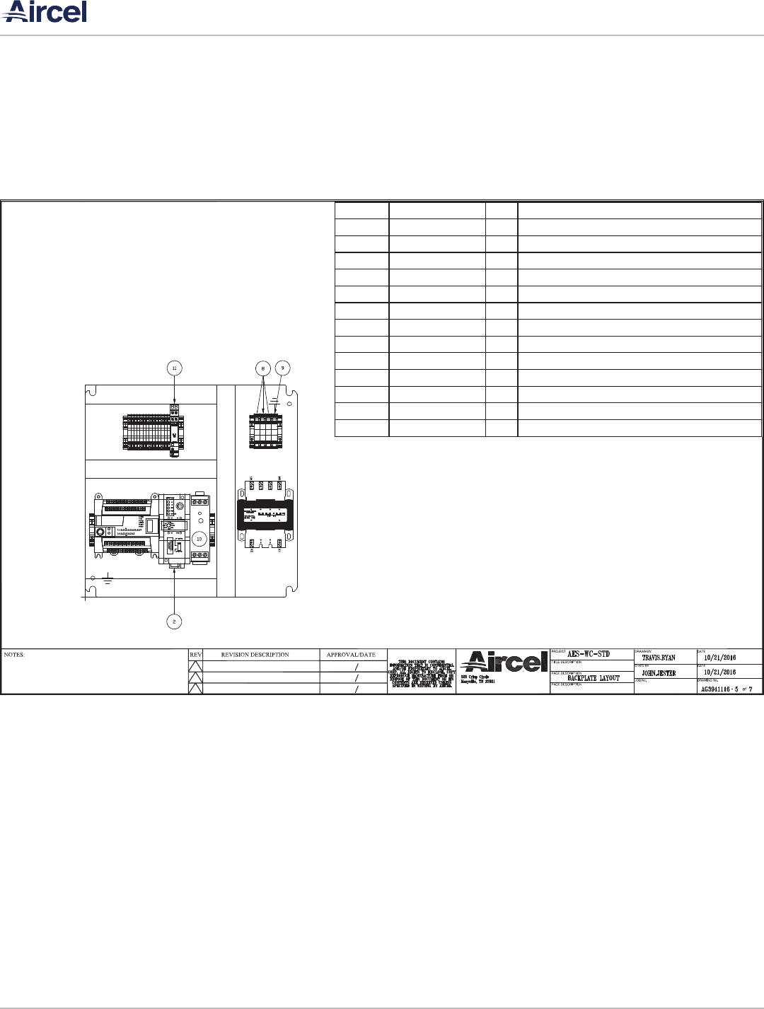
| VF, DHT, AES Series Manual
Refrigerated Air Dryer User Manual
56
ITEM# AIRECLPART# QTY DESCRIPTION
1 AG3934265 1 BACKPLATEFITS16x16ENCLOSURE
2 AG3939621 1 COMMUNICATIONMODULE
3 AG3480020 1 ML‐1100PLC
4 AG3933345 11 TERMINALBLOCK,GRAY,J3
5 AG3933672 3 TERMINALBLOCK,BLUE,J3
6 AG3253101 4 TERMINALBLOCK,GREEN/YELLOW,J3
7 AG3251901 6 ENDANCHOR
8 AG3480612 3 TE RMINALBLOCK,GRAY,J10
9 AG3480613 1 TE RMINALBLOCK,GREEN/YELLOW,J10
10 AG3934654 1 POWERSUPPLY,24VDC,30WATTS
11 AG3948855 1 RELAY,DPDT
12 1C932208‐US 1 PLCCABLE
13
AG3254701
1 TRANSFORMER,150VA
B.4 AES Series - Water-Cooled Models 600 - 2,000 scfm; 3 Phase, 460 Volt, 60 Hz

VF, DHT, AES Series Manual |
Refrigerated Air Dryer User Manual
57
ITEM# AIRECLPART# QTY DESCRIPTION
13 AG3934264 1 ENCLOSURE,16x16x6
14 AG3992107 1 C400HMIDISPLAY
15 AG3939622 1 SWITCH,2‐POSITION
16 AG3939623 1 LIGHT,PILOT,120VAC,GREEN
17 AG3939624 1 LIGHT,PILOT,120VAC,RED
B.4 AES Series - Water-Cooled Models 600 - 2,000 scfm; 3 Phase, 460 Volt, 60 Hz
| VF, DHT, AES Series Manual
Refrigerated Air Dryer User Manual
58
AIRECLPART# QTY DESCRIPTION
AG3934264 1 ENCLOSURE,16x16x6
AG3934265 1 B ACKPLATEFITS16x16ENCLOSURE
AG3939621 1 COMMUNICATIONMODULE
AG3480020 1 ML‐1100PLC
AG3992107 1 C400HMIDISPLAY
AG3933345 11 TERMINALBLOCK,GRAY,J3
AG3933672 3 TERMINALBLOCK,BLUE,J3
AG3253101 4 TERMINALBLOCK,GREEN/YELLOW,J3
AG3251901 6 ENDANCHOR
AG3480612 3 TERMINALBLOCK,GRAY,J10
AG3480613 1 TERMINALBLOCK,GREEN/YELLOW,J10
AG3934654 1 POWERSUPPLY,24VDC,30WATTS
AG3948855 1 RELAY,DPDT
AG3939622 1 S WITCH,2‐POSITION
AG3939623 1 LIGHT,PILOT,120VAC,GREEN
A IRECLPART# QTY DESCRIPTION
AG3287701 2 CONNECTOR,CONDUIT,90°,3/8"
AG3313601 2 CONNECTOR,CONDUIT,90°,1/2"
AG3480860 5 CONDUIT,SEALTITE,1/2"
AG3480861 5 CONDUIT,SEALTITE,3/8"
1C932208 ‐US 1 PLCCABLE
AG3254701 1 TRANSFORMER,150VA
AG3948950 2 FUSE,.75AMP
AG3998925 1 XC643CONTROLLER
AG3998926 1 COMMUNICATIONCABLE
AG3374201 37 WIRE,16AWG,RED
AG3374901 14 WIRE,16AWG,WHITE
AG3371801 13 WIRE,16AWG,BLUE
AG3465901 13 WIRE,16AWG,WHITE/BLUESTRIPE
AG3372301 14 WIRE,16AWG,GREEN
AG3373901 10 WIRE,16AWG,ORANGE
B.4 AES Series - Water-Cooled Models 600 - 2,000 scfm; 3 Phase, 460 Volt, 60 Hz

VF, DHT, AES Series Manual |
Refrigerated Air Dryer User Manual
59
APPENDIX C: MATERIAL SAFETY DATA SHEETS
June 10, 2015 (rev. 1)
SAFETY DATA SHEET R-134a
1
1. IDENTIFICATION
PRODUCT NAME: Refrigerant 134a
SYNONYMS: R-134a, REFRIGERANT 134a, HFC 134a,
RECOMMENDED USE: Refrigerant
DISTRIBUTOR: Hudson Technologies Company
ADDRESS: PO Box 1541
One Blue Hill Plaza
Pearl River, NY 10965
EMERGENCY PHONE: 1- 800-501-4376
CHEMTREC PHONE: 1-800-424-9300
INFORMATION PHONE: 1-800-953-2244
2. HAZARDS IDENTIFICATION
EMERGENCY OVERVIEW: Colorless, volatile liquid with ethereal and faint sweetish odor. Non-flammable
material. Contact with the liquid may cause frostbite. Overexposure to vapors by inhalation may cause
dizziness and loss of concentration. At higher levels, central nervous system depression and cardiac
arrhythmia may result from exposure. Vapors displace air and can cause asphyxiation in confined spaces. At
higher temperatures, (>250°C), decomposition products may include Hydrochloric Acid (HCL), Hydrofluoric
Acid (HF) and carbonyl halides.
HAZARD
CLASSIFICATION: Gases Under Pressure
USDOT Hazard Class 2.2, Non-Flammable Gas
SIGNAL WORD: WARNING
HAZARD
STATEMENTS: Gas under pressure; may explode if heated
Harmful in contact with skin - may cause frostbite
May displace oxygen and cause rapid suffocation. Inhalation of high concentrations
of vapor is harmful and may cause heart irregularities, unconsciousness, or death.
C.1 R-134a Refrigerant

| VF, DHT, AES Series Manual
Refrigerated Air Dryer User Manual
60
C.1 R-134a Refrigerant
June 10, 2015 (rev. 1)
SAFETY DATA SHEET R-134a
2
PRECAUTIONARY STATEMENTS
PREVENTION: Do not breathe vapors. Use only with adequate ventilation - never in a closed
space. Wear protective gloves. Wear eye protection.
RESPONSE: If inhaled: Remove person to fresh air and keep comfortable for breathing.
Immediately call a physician. If not breathing, give artificial respiration, preferably
mouth to mouth.
If breathing is difficult, give oxygen. Avoid stimulants. Do not give adrenalin
If on skin: Wash with plenty of water (not hot water) or use other means to warm
skin slowly.
If in eyes: Rinse cautiously with water for several minutes. Remove contact lenses,
if present and easy to do. Continue rinsing. Call a physician.
STORAGE: Protect from sunlight. Store in well-ventilated place.
Do not heat above 120°F (50°C). Do not store in damp areas.
DISPOSAL: Comply with Federal, State and local regulations. Reclaim by distillation or remove
to a permitted waste disposal facility
CARCINOGENICITY: Ingredients found on one of the OSHA designated carcinogen lists are listed below.
INGREDIENT NAME
NTP STATUS IARC STATUS OSHA LIST
No ingredients listed in this section
3. COMPOSITION / INFORMATION ON INGREDIENTS
PRODUCT NAME: Refrigerant 134a
SYNONYMS: R-134a, REFRIGERANT 134a, HFC 134a
INGREDIENT NAME CAS NUMBER WEIGHT %
Ingredient Name
CAS Number
1,1,1,2-Tetrafluoroethane (HFC-134a) 811-97-2
Trace impurities and additional material names not listed above may also appear in Section 15 toward the end of this
Safety Data Sheet.
4. FIRST AID MEASURES
SKIN: Promptly flush skin with water until all chemical is removed. If there is evidence of frostbite,
bathe (do not rub) with lukewarm (not hot) water. If water is not available, cover with a clean, soft cloth or similar
covering. Get medical attention if symptoms persist.
EYES: Immediately flush eyes with large amounts of water for at least 15 minutes (in case of frostbite
water should be lukewarm, not hot) lifting eyelids occasionally to facilitate irrigation. Get medical attention if
symptoms persist.

VF, DHT, AES Series Manual |
Refrigerated Air Dryer User Manual
61
C.1 R-134a Refrigerant
June 10, 2015 (rev. 1)
SAFETY DATA SHEET R-134a
3
INHALATION: Immediately remove to fresh air. If breathing has stopped, give artificial respiration. Use
oxygen as required, provided a qualified operator is available. Get medical attention. Do not give epinephrine
(adrenaline).
INGESTION: Ingestion is unlikely because of the physical properties and is not expected to be hazardous.
In case of accidental ingestion, get medical attention. Do not induce vomiting unless instructed to do so by a
physician.
ADVICE TO PHYSICIAN: Because of the possible disturbances of cardiac rhythm, catecholamine drugs,
such as epinephrine, should be used with special caution and only in situations of emergency life support. Treatment
of overexposure should be directed at the control of symptoms and the clinical conditions.
5. FIRE FIGHTING MEASURES
FLAMMABLE LIMITS IN AIR, UPPER: N/A
(% BY VOLUME) LOWER: N/A
FLASH POINT: None
AUTOIGNITION TEMPERATURE: F: >1369; C: >743
NFPA HAZARD CLASSIFICATION
HEALTH: 1 FLAMMABILITY: 0 REACTIVITY: 1 OTHER:
EXTINGUISHING MEDIA: Appropriate for combustibles in the area.
SPECIAL FIRE FIGHTING PROCEDURES: Use water spray to cool containers. Self-contained breathing
apparatus (SCBA) is required if cylinders rupture and contents are released under fire conditions.
UNUSUAL FIRE AND EXPLOSION HAZARDS: Cylinders may rupture under fire conditions. HFC 134a
should not be permitted to mix with air above atmospheric pressure or at high temperatures, or in an oxygen
enriched environment, since under such conditions it can become combustible in the presence of an ignition source.
HAZARDOUS DECOMPOSITION PRODUCTS: Under high temperatures, this product can form hydrofluoric
acid, and possibly carbonyl fluoride.
6. ACCIDENTAL RELEASE MEASURES
IN CASE OF SPILL OR OTHER RELEASE:
(Always wear recommended personal protective equipment.)
Evacuate unprotected personnel. Protected personnel should remove ignition sources and shut off leak, if without
risk, and provide ventilation. Use self-contained breathing apparatus (SCBA) for large spills or releases.
Unprotected personnel should not return until air has been tested and determined safe, including low- lying areas.
Spills and releases may have to be reported to Federal and/or local authorities. See Section 15 regarding
reporting requirements.

| VF, DHT, AES Series Manual
Refrigerated Air Dryer User Manual
62
C.1 R-134a Refrigerant
June 10, 2015 (rev. 1)
SAFETY DATA SHEET R-134a
4
7. HANDLING AND STORAGE
NORMAL HANDLING: Always wear recommended personal protective equipment.
Avoid breathing vapors and liquid contact with eyes, skin or clothing. Do not puncture or drop cylinders, expose
them to open flame or excessive heat. Use authorized cylinders only. Follow standard safety precautions for
handling and use of compressed gas cylinders. R-134A should not be mixed with air above atmospheric pressure
for leak testing or any other purpose.
STORAGE RECOMMENDATIONS:
Store in a cool, well-ventilated area of low fire risk and keep out of direct sunlight. Protect cylinder and its fittings
from physical damage. Storage in subsurface locations should be avoided. Close valve tightly after use and when
empty. Cylinder temperatures should not exceed 52° C (125° F).
8. EXPOSURE CONTROLS / PERSONAL PROTECTION
ENGINEERING CONTROLS: Provide local ventilation at filling zones and areas where leakage is probable.
Mechanical (general) ventilation may be adequate for other operating and storage areas.
PERSONAL PROTECTIVE EQUIPMENT
SKIN PROTECTION: Skin contact with refrigerant may cause frostbite. General work clothing and
gloves (leather) should provide adequate protection. If prolonged contact with the liquid or gas is
anticipated, insulated gloves constructed of PVA, neoprene or butyl rubber should be used. Any
contaminated clothing should be promptly removed and washed before reuse.
EYE PROTECTION: For normal conditions, wear safety glasses. Where there is reasonable
probability of liquid contact, wear chemical safety goggles.
RESPIRATORY PROTECTION: None generally required for adequately ventilated work situations.
For accidental release or non-ventilated situations, or release into confined space, where the concentration
may be above the PEL of 1,000 ppm, use a self-contained, NIOSH- approved breathing apparatus or
supplied air respirator. For escape: use the former or a NIOSH-approved gas mask with organic vapor
canister.
ADDITIONAL RECOMMENDATIONS: Where contact with liquid is likely, such as in a spill or leak,
impervious boots and clothing should be worn. High dose-level warning signs are recommended for areas
of principle exposure. Provide eyewash stations and quick-drench shower facilities at convenient locations.
For tank cleaning operations, see OSHA regulations, 29 CFR 1910.132 and 29 CFR 1910.133.
EXPOSURE GUIDELINES
INGREDIENT NAME
ACGIH TLV OSHA PEL OTHER LIMIT
1,1,1,2-Tetrafluoroethane None None *1000 ppm TWA (8hr)
* = Workplace Environmental Exposure Level (AIHA)
OTHER EXPOSURE LIMITS FOR POTENTIAL DECOMPOSITION PRODUCTS:
Hydrogen Fluoride: ACGIH TLV: 3 ppm ceiling

VF, DHT, AES Series Manual |
Refrigerated Air Dryer User Manual
63
C.1 R-134a Refrigerant
June 10, 2015 (rev. 1)
SAFETY DATA SHEET R-134a
5
9. PHYSICAL AND CHEMICAL PROPERTIES
APPEARANCE: Clear, colorless liquified gas
ODOR: Slight ethereal
PHYSICAL STATE: liquified gas
BOILING POINT (@ 736 mm Hg): F: -15.7
C: -26.5
VAPOR PRESSURE (psia): 96 @ 77F (25C)
VAPOR DENSITY (AIR = 1): 3.6 @ 77F (25C)
SPECIFIC GRAVITY (H2O = 1): 1.208 @ 77F (25C)
EVAPORATION RATE (CCL4 =1): >1
SOLUBILITY IN WATER (@14.7 psia): 0.15 WT% @ 77F (25C)
PERCENT SOLIDS BY WEIGHT: Gas
PERCENT VOLATILE: 100% By Wt
VOLATILE ORGANIC COMPOUNDS (VOC): Gas
10. STABILITY AND REACTIVITY
NORMALLY STABLE (CONDITIONS TO AVOID):
The product is stable.
Do not mix with oxygen or air above atmospheric pressure. Any source of high temperature, such as lighted
cigarettes, flames, hot spots or welding may yield toxic and/or corrosive decomposition products.
INCOMPATIBILITIES:
Under specific conditions: e.g. very high temperatures and/or appropriate pressures – Freshly abraded aluminum
surfaces may cause strong exothermic reaction. Chemically active metals: potassium, calcium, powdered aluminum,
magnesium and zinc.
HAZARDOUS DECOMPOSITION PRODUCTS:
Halogens, halogen acids and possibly carbonyl halides. These materials are toxic and irritating.
HAZARDOUS POLYMERIZATION:
Will not occur.
11. TOXICOLOGICAL INFORMATION
IMMEDIATE (ACUTE) EFFECTS:
LC
50 : 4 hr. (rat) - > 500,000 ppm / Cardiac Sensitization threshold (dog) > 80,000 ppm
DELAYED (SUBCHRONIC AND CHRONIC) EFFECTS:
Teratogenic NOEL(rate and rabbit) – 40,000 ppm
Subchronic inhalation NOEL (rat) - 50,000 ppm / Chronic NOEL – 10,000 ppm
OTHER DATA:
Not active in four genetic studies
Toxicity to reproduction: Did not show mutagenic or teratogenic effects in animal experiments

| VF, DHT, AES Series Manual
Refrigerated Air Dryer User Manual
64
C.1 R-134a Refrigerant
June 10, 2015 (rev. 1)
SAFETY DATA SHEET R-134a
6
12. ECOLOGICAL INFORMATION
Aquatic Toxicity:
48-hour EC50, Daphnia magna: 980 mg/L
96-hour LC50. Rainbow trout: >450mg/L
Degradability (BOD): R-134A is a gas at room temperature; therefore, it is unlikely to remain in water.
Octanol Water Partition Coefficient: Unknown for mixture
13. DISPOSAL CONSIDERATIONS
RCRA - Not a hazardous waste.
OTHER DISPOSAL CONSIDERATIONS:
Disposal must comply with federal, state, and local disposal or discharge laws. R-134A is subject to U.S.
Environmental Protection Agency Clean Air Act Regulations Section 608 in 40 CFR Part 82 regarding refrigerant
recycling.
The information offered here is for the product as shipped. Use and/or alterations to the product such as
mixing with other materials may significantly change the characteristics of the material and alter the RCRA
classification and the proper disposal method.
14. TRANSPORT INFORMATION
HAZARD CLASS: 2.2
ID NUMBER: UN3159
PACKING GROUP: N/A
LABEL STATEMENT: NONFLAMMABLE GAS
SHIPPING CONTAINERS: Tank Cars, cylinders, ton tanks
For additional information on shipping regulations affecting this material, contact the information number found in
Section 1.
15. REGULATORY INFORMATION
TOXIC SUBSTANCES CONTROL ACT (TSCA)
TSCA INVENTORY STATUS: Components listed on the TSCA inventory
OTHER TSCA ISSUES: None
SARA TITLE III / CERCLA
“Reportable Quantities” (RQs) and/or “Threshold Planning Quantities” (TPQs) exist for the following ingredients.
INGREDIENT NAME
SARA / CERCLA RQ (lb.) SARA EHS TPQ (lb.)
No ingredients listed in this section

VF, DHT, AES Series Manual |
Refrigerated Air Dryer User Manual
65
C.1 R-134a Refrigerant
June 10, 2015 (rev. 1)
SAFETY DATA SHEET R-134a
7
Spills or releases resulting in the loss of any ingredient at or above its RQ requires immediate notification to
the National Response Center [(800) 424-8802] and to your Local Emergency Planning Committee.
SECTION 311 HAZARD CLASS: IMMEDIATE PRESSURE
SARA 313 TOXIC CHEMICALS:
The following ingredients are SARA 313 “Toxic Chemicals”. CAS numbers and weight percents are found
in Section 3.
INGREDIENT NAME
COMMENT
No ingredients listed in this section
STATE RIGHT-TO-KNOW
In addition to the ingredients found in Section 3, the following are listed for state right-to-know purposes.
INGREDIENT NAME
WEIGHT % COMMENT
No ingredients listed in this section
ADDITIONAL REGULATORY INFORMATION:
R-134A is subject to U.S. Environmental Protection Agency Clean Air Act Regulations at 40 CFR Part 82.
WARNING:
Do not vent to the atmosphere. To comply with provisions of the U.S. Clean Air Act, any residual must be
recovered.
1,1,1,2-Tetrafluoroethane (HFC-134a), is a greenhouse gas which may contribute to global warming.
16. OTHER INFORMATION
DISCLAIMER: The above information is based upon technical information believed to be accurate but does
not purport to all-inclusive and should be used only as a guide. Hudson Technologies Company shall not be
held liable for any damage from handling or from contact with this product. No warranty of merchantability
or any warranty, express or implied is made with respect to such information
| VF, DHT, AES Series Manual
Refrigerated Air Dryer User Manual
66
C.2 R-404a Refrigerant
June 10, 2015 (rev. 1)
SAFETY DATA SHEET R-404A
1
1. IDENTIFICATION
PRODUCT NAME: Refrigerant 404A
SYNONYMS: R-404A, REFRIGERANT 404A
RECOMMENDED USE: Refrigerant
DISTRIBUTOR: Hudson Technologies Company
ADDRESS: PO Box 1541
One Blue Hill Plaza
Pearl River, NY 10965
EMERGENCY PHONE: 1- 800-501-4376
CHEMTREC PHONE: 1-800-424-9300
INFORMATION PHONE: 1-800-953-2244
2. HAZARDS IDENTIFICATION
EMERGENCY OVERVIEW: Colorless, volatile liquid with ethereal and faint sweetish odor. Non-flammable
material. Contact with the liquid may cause frostbite. Overexposure to vapors by inhalation may cause
dizziness and loss of concentration. At higher levels, central nervous system depression and cardiac
arrhythmia may result from exposure. Vapors displace air and can cause asphyxiation in confined spaces. At
higher temperatures, (>250°C), decomposition products may include Hydrochloric Acid (HCL), Hydrofluoric
Acid (HF) and carbonyl halides.
HAZARD
CLASSIFICATION: Gases Under Pressure
USDOT Hazard Class 2.2, Non-Flammable Gas
SIGNAL WORD: WARNING
HAZARD
STATEMENTS: Gas under pressure; may explode if heated
Harmful in contact with skin - may cause frostbite
May displace oxygen and cause rapid suffocation. Inhalation of high concentrations
of vapor is harmful and may cause heart irregularities, unconsciousness, or death.

VF, DHT, AES Series Manual |
Refrigerated Air Dryer User Manual
67
C.2 R-404a Refrigerant
June 10, 2015 (rev. 1)
SAFETY DATA SHEET R-404A
2
PRECAUTIONARY STATEMENTS
PREVENTION: Do not breathe vapors. Use only with adequate ventilation - never in a closed
space. Wear protective gloves. Wear eye protection.
RESPONSE: If inhaled: Remove person to fresh air and keep comfortable for breathing.
Immediately call a physician. If not breathing, give artificial respiration, preferably
mouth to mouth.
If breathing is difficult, give oxygen. Avoid stimulants. Do not give adrenalin
If on skin: Wash with plenty of water (not hot water) or use other means to warm
skin slowly.
If in eyes: Rinse cautiously with water for several minutes. Remove contact lenses,
if present and easy to do. Continue rinsing. Call a physician.
STORAGE: Protect from sunlight. Store in well-ventilated place.
Do not heat above 120°F (50°C). Do not store in damp areas.
DISPOSAL: Comply with Federal, State and local regulations. Reclaim by distillation or remove
to a permitted waste disposal facility
CARCINOGENICITY: Ingredients found on one of the OSHA designated carcinogen lists are listed below.
INGREDIENT NAME
NTP STATUS IARC STATUS OSHA LIST
No ingredients listed in this section
3. COMPOSITION / INFORMATION ON INGREDIENTS
PRODUCT NAME: Refrigerant 404A
SYNONYMS: R-404A, REFRIGERANT 404A
INGREDIENT NAME CAS NUMBER WEIGHT %
Ingredient Name
CAS Number %
1,1,1-Trifluoroethane (HFC-143a) 420-46-2 52
Pentafluoroethane (HFC-125) 354-33-6 44
1,1,1,2-Tetrafluoroethane (HFC-134a) 811-97-2 4
Trace impurities and additional material names not listed above may also appear in Section 15 toward the end of this
Safety Data Sheet.
4. FIRST AID MEASURES
SKIN: Promptly flush skin with water until all chemical is removed. If there is evidence of frostbite,
bathe (do not rub) with lukewarm (not hot) water. If water is not available, cover with a clean, soft cloth or similar
covering. Get medical attention if symptoms persist.

| VF, DHT, AES Series Manual
Refrigerated Air Dryer User Manual
68
C.2 R-404a Refrigerant
June 10, 2015 (rev. 1)
SAFETY DATA SHEET R-404A
3
EYES: Immediately flush eyes with large amounts of water for at least 15 minutes (in case of frostbite
water should be lukewarm, not hot) lifting eyelids occasionally to facilitate irrigation. Get medical attention if
symptoms persist.
INHALATION: Immediately remove to fresh air. If breathing has stopped, give artificial respiration. Use
oxygen as required, provided a qualified operator is available. Get medical attention. Do not give epinephrine
(adrenaline).
INGESTION: Ingestion is unlikely because of the physical properties and is not expected to be hazardous.
In case of accidental ingestion, get medical attention. Do not induce vomiting unless instructed to do so by a
physician.
ADVICE TO PHYSICIAN: Because of the possible disturbances of cardiac rhythm, catecholamine drugs,
such as epinephrine, should be used with special caution and only in situations of emergency life support. Treatment
of overexposure should be directed at the control of symptoms and the clinical conditions.
5. FIRE FIGHTING MEASURES
FLAMMABLE PROPERTIES
FLASH POINT: No flash point
FLASH POINT METHOD: Not applicable
AUTOIGNITION TEMPERATURE: not determined
UPPER FLAME LIMIT (volume % in air): None*
LOWER FLAME LIMIT (volume % in air): None*
FLAME PROPAGATION RATE (solids): Not applicable
OSHA FLAMMABILITY CLASS: Not applicable
*Based on ASHRAE Standard 34 with match ignition
EXTINGUISHING MEDIA:
Use any standard agent – choose the one most appropriate for type of surrounding fire (material itself is not
flammable)
UNUSUAL FIRE AND EXPLOSION HAZARDS:
Cylinders may rupture under fire conditions. Decomposition may occur.
R-404A is not flammable in air at temperatures up to 100° C (212° F) at atmospheric pressure. However, this
material will become combustible when mixed with air at elevated pressure and/or temperature in the presence of an
ignition sources. R-404A can also become combustible in an oxygen enriched environment. Contact with certain
reactive metals may result in formation of explosive or exothermic reactions under specific conditions (e.g. very
high temperatures and/or appropriate pressures.
SPECIAL FIRE FIGHTING PRECAUTIONS/INSTRUCTIONS:
In the event of fire, firefighters should wear self-contained, NIOSH-approved breathing apparatus for protection
against possible toxic decomposition products. Proper eye and skin protection should be provided. Use water spray
to keep fire-exposed cylinders/tanks cool.

VF, DHT, AES Series Manual |
Refrigerated Air Dryer User Manual
69
C.2 R-404a Refrigerant
June 10, 2015 (rev. 1)
SAFETY DATA SHEET R-404A
4
6. ACCIDENTAL RELEASE MEASURES
IN CASE OF SPILL OR OTHER RELEASE:
(Always wear recommended personal protective equipment.)
Evacuate unprotected personnel. Protected personnel should remove ignition sources and shut off leak, if without
risk, and provide ventilation. Use self-contained breathing apparatus (SCBA) for large spills or releases.
Unprotected personnel should not return until air has been tested and determined safe, including low- lying areas.
Spills and releases may have to be reported to Federal and/or local authorities. See Section 15 regarding
reporting requirements.
7. HANDLING AND STORAGE
NORMAL HANDLING: Always wear recommended personal protective equipment.
Avoid breathing vapors and liquid contact with eyes, skin or clothing. Do not puncture or drop cylinders, expose
them to open flame or excessive heat. Use authorized cylinders only. Follow standard safety precautions for
handling and use of compressed gas cylinders. R-404A should not be mixed with air above atmospheric pressure
for leak testing or any other purpose.
STORAGE RECOMMENDATIONS:
Store in a cool, well-ventilated area of low fire risk and keep out of direct sunlight. Protect cylinder and its fittings
from physical damage. Storage in subsurface locations should be avoided. Close valve tightly after use and when
empty. Cylinder temperatures should not exceed 52° C (125° F).
8. EXPOSURE CONTROLS / PERSONAL PROTECTION
ENGINEERING CONTROLS: Provide local ventilation at filling zones and areas where leakage is probable.
Mechanical (general) ventilation may be adequate for other operating and storage areas.
PERSONAL PROTECTIVE EQUIPMENT
SKIN PROTECTION: Skin contact with refrigerant may cause frostbite. General work clothing and
gloves (leather) should provide adequate protection. If prolonged contact with the liquid or gas is
anticipated, insulated gloves constructed of PVA, neoprene or butyl rubber should be used. Any
contaminated clothing should be promptly removed and washed before reuse.
EYE PROTECTION: For normal conditions, wear safety glasses. Where there is reasonable
probability of liquid contact, wear chemical safety goggles.
RESPIRATORY PROTECTION: None generally required for adequately ventilated work situations.
For accidental release or non-ventilated situations, or release into confined space, where the concentration
may be above the PEL of 1,000 ppm, use a self-contained, NIOSH- approved breathing apparatus or
supplied air respirator. For escape: use the former or a NIOSH-approved gas mask with organic vapor
canister.

| VF, DHT, AES Series Manual
Refrigerated Air Dryer User Manual
70
C.2 R-404a Refrigerant
June 10, 2015 (rev. 1)
SAFETY DATA SHEET R-404A
5
ADDITIONAL RECOMMENDATIONS: Where contact with liquid is likely, such as in a spill or leak,
impervious boots and clothing should be worn. High dose-level warning signs are recommended for areas
of principle exposure. Provide eyewash stations and quick-drench shower facilities at convenient locations.
For tank cleaning operations, see OSHA regulations, 29 CFR 1910.132 and 29 CFR 1910.133.
EXPOSURE GUIDELINES
INGREDIENT NAME
ACGIH TLV OSHA PEL OTHER LIMIT
Pentafluoroethane None None *1000 ppm TWA (8hr)
1,1,1-Trifluoroethane None None *1000 ppm TWA (8hr)
1,1,1,2-Tetrafluoroethane None None *1000 ppm TWA (8hr)
* = Workplace Environmental Exposure Level (AIHA)
OTHER EXPOSURE LIMITS FOR POTENTIAL DECOMPOSITION PRODUCTS:
Hydrogen Fluoride: ACGIH TLV: 3 ppm ceiling
9. PHYSICAL AND CHEMICAL PROPERTIES
APPEARANCE: Clear, colorless liquid and vapor
PHYSICAL STATE: Liquefied gas - gas at ambient temperatures
MOLECULAR WEIGHT: 97.6
ODOR: Faint ethereal odor
SPECIFIC GRAVITY (water = 1.0): 1.05 @ 25°C (77°F)
SOLUBILITY IN WATER (weight %): Unknown
pH: Neutral
BOILING POINT: -46.7°C (-52.1°F)
FREEZING POINT: Not determined
VAPOR PRESSURE: 182.1 psia @ 25°C (77°F)
VAPOR DENSITY
(air = 1.0): 3.43 25°C (77°F)
EVAPORATION RATE: >1
COMPARED TO: CC1
4 = 1
% VOLATILES: 100
FLASH POINT: Not applicable
(Flash point method and additional flammability data are found in Section 5.)
10. STABILITY AND REACTIVITY
NORMALLY STABLE (CONDITIONS TO AVOID):
The product is stable.
Do not mix with oxygen or air above atmospheric pressure. Any source of high temperature, such as lighted
cigarettes, flames, hot spots or welding may yield toxic and/or corrosive decomposition products.
INCOMPATIBILITIES:
Under specific conditions: e.g. very high temperatures and/or appropriate pressures – Freshly abraded aluminum
surfaces may cause strong exothermic reaction. Chemically active metals: potassium, calcium, powdered aluminum,
magnesium and zinc.

VF, DHT, AES Series Manual |
Refrigerated Air Dryer User Manual
71
C.2 R-404a Refrigerant
June 10, 2015 (rev. 1)
SAFETY DATA SHEET R-404A
6
HAZARDOUS DECOMPOSITION PRODUCTS:
Halogens, halogen acids and possibly carbonyl halides. These materials are toxic and irritating.
HAZARDOUS POLYMERIZATION:
Will not occur.
11. TOXICOLOGICAL INFORMATION
IMMEDIATE (ACUTE) EFFECTS:
HFC-134a: LC
50 : 4 hr. (rat) - > 500,000 ppm / Cardiac Sensitization threshold (dog) > 80,000 ppm
HFC-143a: LC
50 : 4 hr. (rat) - > 540,000 ppm / Cardiac Sensitization threshold (dog) > 250,000 ppm
HFC-125: LC
50: 4 hr. (rat) - > 800,000 ppm / Cardiac Sensitization threshold (dog) 75,000 ppm
DELAYED (SUBCHRONIC AND CHRONIC) EFFECTS:
HFC-134a: Teratogenic NOEL(rate and rabbit) – 40,000 ppm
Subchronic inhalation NOEL (rat) - 50,000 ppm / Chronic NOEL – 10,000 ppm
HFC-125: Teratogenic NOEL (rat and rabbit) – 50,000 ppm
Subchronic inhalation (rat) NOEL - >50,000 ppm / Chronic NOEL – 10,000 ppm
HFC-143a: Teratogenic NOEL (rat and rabbit) – 50,000 ppm
Subchronic inhalation NOEL (rat) - >
50,000 ppm
OTHER DATA:
HFC-125, HFC-134a: Not active in four genetic studies
HFC-143a: Not active in two genetic studies
Toxicity to reproduction: Did not show mutagenic or teratogenic effects in animal experiments
12. ECOLOGICAL INFORMATION
Aquatic Toxicity:
HFC 143a 96-hour LC50. Rainbow trout: >40mg/L
HFC 134a 48-hour EC50, Daphnia magna: 980 mg/L
96-hour LC50. Rainbow trout: >450mg/L
Degradability (BOD): R-404A is a gas at room temperature; therefore, it is unlikely to remain in water.
Octanol Water Partition Coefficient: Unknown for mixture
13. DISPOSAL CONSIDERATIONS
RCRA - Not a hazardous waste.
OTHER DISPOSAL CONSIDERATIONS:
Disposal must comply with federal, state, and local disposal or discharge laws. R-404A is subject to U.S.
Environmental Protection Agency Clean Air Act Regulations Section 608 in 40 CFR Part 82 regarding refrigerant
recycling.

| VF, DHT, AES Series Manual
Refrigerated Air Dryer User Manual
72
C.2 R-404a Refrigerant
June 10, 2015 (rev. 1)
SAFETY DATA SHEET R-404A
7
The information offered here is for the product as shipped. Use and/or alterations to the product such as
mixing with other materials may significantly change the characteristics of the material and alter the RCRA
classification and the proper disposal method.
14. TRANSPORT INFORMATION
US DOT PROPER SHIPPING NAME: Refrigerant Gas R-404A
US DOT HAZARD CLASS: 2.2
US DOT ID NUMBER: UN3337
PRIMARY LABEL: Nonflammable gas
SHIPPING CONTAINERS: Tank Cars, cylinders, ton tanks
For additional information on shipping regulations affecting this material, contact the information number found in
Section 1.
15. REGULATORY INFORMATION
TOXIC SUBSTANCES CONTROL ACT (TSCA)
TSCA INVENTORY STATUS: Components listed on the TSCA inventory
OTHER TSCA ISSUES: None
SARA TITLE III / CERCLA
“Reportable Quantities” (RQs) and/or “Threshold Planning Quantities” (TPQs) exist for the following ingredients.
INGREDIENT NAME
SARA / CERCLA RQ (lb.) SARA EHS TPQ (lb.)
No ingredients listed in this section
Spills or releases resulting in the loss of any ingredient at or above its RQ requires immediate notification to
the National Response Center [(800) 424-8802] and to your Local Emergency Planning Committee.
SECTION 311 HAZARD CLASS: IMMEDIATE PRESSURE
SARA 313 TOXIC CHEMICALS:
The following ingredients are SARA 313 “Toxic Chemicals”. CAS numbers and weight percents are found
in Section 3.
INGREDIENT NAME
COMMENT
No ingredients listed in this section
STATE RIGHT-TO-KNOW
In addition to the ingredients found in Section 3, the following are listed for state right-to-know purposes.
INGREDIENT NAME
WEIGHT % COMMENT
No ingredients listed in this section

VF, DHT, AES Series Manual |
Refrigerated Air Dryer User Manual
73
C.2 R-404a Refrigerant
June 10, 2015 (rev. 1)
SAFETY DATA SHEET R-404A
8
ADDITIONAL REGULATORY INFORMATION:
R-404A is subject to U.S. Environmental Protection Agency Clean Air Act Regulations at 40 CFR Part 82.
WARNING:
Do not vent to the atmosphere. To comply with provisions of the U.S. Clean Air Act, any residual must be
recovered.
Contains Pentafluoroethane (HFC-125), 1,1,1-Trifluoroethane (HFC-143a) and 1,1,1,2-Tetrafluoroethane
(HFC-134a), greenhouse gases which may contribute to global warming.
16. OTHER INFORMATION
DISCLAIMER: The above information is based upon technical information believed to be accurate but does
not purport to all-inclusive and should be used only as a guide. Hudson Technologies Company shall not be
held liable for any damage from handling or from contact with this product. No warranty of merchantability
or any warranty, express or implied is made with respect to such information

| VF, DHT, AES Series Manual
Refrigerated Air Dryer User Manual
74
DATE SERVICE PERFORMED NOTES
NOTES

VF, DHT, AES Series Manual |
Refrigerated Air Dryer User Manual
75
DATE SERVICE PERFORMED NOTES
NOTES

| VF, DHT, AES Series Manual
Refrigerated Air Dryer User Manual
76
DATE SERVICE PERFORMED NOTES
NOTES

VF, DHT, AES Series Manual |
Refrigerated Air Dryer User Manual
77
DATE SERVICE PERFORMED NOTES
NOTES
| VF, DHT, AES Series Manual
Refrigerated Air Dryer User Manual
78
DATE SERVICE PERFORMED NOTES
NOTES

VF, DHT, AES Series Manual |
Refrigerated Air Dryer User Manual
79
WARRANTY INFORMATION
Aircel warrants that its Standard Refrigerated Air Dryers are
free from defects in materials and workmanship for two
years from the date of invoice. Warranty coverage for this
time period will be parts and labor for the rst year and parts
only for the second. Custom engineered products, desiccant
dryers, chillers and nitrogen generators are warranted to be
free from defects in materials and workmanship for one year
from date of invoice. Warranty coverage for this time period
will be for parts and labor.
Aircel warranty excludes damages due to corrosion, lack of
proper maintenance, incorrect installation, modication,
or misapplication of equipment. Routine maintenance or
adjustment required under normal operation as outlined
in the Aircel operation and maintenance manuals are not
covered under warranty.
Once Aircel has been given adequate opportunity to remedy
any defects in material or workmanship in accordance with
Aircel Warranty Policy and Procedures, Aircel retains the sole
option to accept return of the goods, with freight paid by the
purchaser, and to refund the purchase price for the goods
after conrming the goods are returned undamaged and in
usable condition. Such a refund will be the full extent of Aircel
liability. Aircel shall not be liable for any other costs, expenses
or damages whether direct, indirect, special, incidental,
consequential or otherwise. The terms of this warranty may
be modied only by a special warranty document signed by a
CEO, General Manager or Vice President of Aircel.
There exist no other representations, warranties or guarantees
except as stated in this paragraph and all other warranties,
including merchantability and tness for a particular purpose
whether express or implied, are hereby expressly excluded
and disclaimed.

Parts & Service
For genuine Aircel replacement parts, call
800.767.4599
For faster service, please have your unit model
and serial number, part number, or description.
Aircel LLC | 323 Crisp Circle | Maryville, TN 37801 | 865.767.4599 | airceldryers.com
