
L-802A 36-Inch Airport
Rotating Beacon
(1000 Watt Metal Halide Lamp and PRC)
Document No. 96A0198
Issued: December 1, 1997
Rev. C: May 16, 2001
ETL Certified to FAA Specification
AC 150/5345-12C
ADB
Copyright 2001 by ADB Airfield Solutions, LLC. All rights reserved.

L-802A 36-Inch Airport Rotating Beacon
(1000 Watt Metal Halide Lamp and PRC) Record of Changes
2001 ADB Airfield Solutions, LLC
96A0198C ii
All rights reserved Issued 5/01
Page Rev Description EC No. Checke
d
Approved Date
A Released manual.
KJ WT 12/5/97
12, 39 B Changed part number from 35A0409 to 35A0490.
Changed issued date from July 18, 1997 to
December 1, 1997. Changed 700 W to 1680 W.
3254 KJ WT 2/16/98
All C Changed to new title page. Changed ADB to
ADB Airfield Solutions.
00696 KJ WT 5/16/01
Record of Changes

L-802A 36-Inch Airport Rotating Beacon
(1000 Watt Metal Halide Lamp and PRC) Table of Contents
2001 ADB Airfield Solutions, LLC
96A0198C iii
All rights reserved Issued 5/01
Record of Changes ........................................................................................ ii
Table of Contents ......................................................................................... iii
Warranties .................................................................................................... vi
1. Safety ....................................................................................................... 1
Safety Symbols ..................................................................................... 1
Qualified Personnel .............................................................................. 2
Intended Use ........................................................................................ 2
Installation ............................................................................................ 3
Operation .............................................................................................. 3
Action in the Event of a System or Component Malfunction .............. 4
Maintenance and Repair ....................................................................... 4
2. Description ............................................................................................... 5
L-802A Rotating Beacon: Required Equipment .................................. 6
Specifications ....................................................................................... 7
Input Voltage .................................................................................... 7
Input Power ...................................................................................... 7
Lamps ............................................................................................... 7
Rated Lamp Life ............................................................................... 7
Vertical Beam Intensity .................................................................... 7
Beam Center ..................................................................................... 7
Motor ................................................................................................ 8
Flash Rate ......................................................................................... 8
Environmental Operating Conditions ............................................... 8
Paint .................................................................................................. 8
L-802A Glassware ............................................................................ 8
Dimensions ....................................................................................... 8
3. Installation .............................................................................................. 11
Introduction ........................................................................................ 11
Unpacking .......................................................................................... 11
Hoisting .............................................................................................. 11
Mounting Beacon ............................................................................... 11
Leveling Beacon................................................................................. 12
Wiring ................................................................................................ 12
Elevating Lamp .................................................................................. 12
Table of Contents

L-802A 36-Inch Airport Rotating Beacon
(1000 Watt Metal Halide Lamp and PRC) Table of Contents
2001 ADB Airfield Solutions, LLC
96A0198C iv
All rights reserved Issued 5/01
4. Maintenance ........................................................................................... 14
Maintenance Schedule ....................................................................... 14
Maintenance Procedures .................................................................... 15
Replacing Lamp .............................................................................. 15
Cleaning Lenses .............................................................................. 15
Cleaning Lamp Housing ................................................................ 15
Lubricating Parts ............................................................................ 15
Adjusting Slip Clutch ..................................................................... 16
5. Troubleshooting ..................................................................................... 19
6. Repair ..................................................................................................... 20
Replacing Motor................................................................................. 20
Replacing Worm or Worm Gear ........................................................ 25
Replacing Slip Clutch ........................................................................ 29
Replacing Power Rotary Connector ................................................... 29
Removing PRC ............................................................................... 30
Replacing PRC ............................................................................... 34
Replacing Lamp ................................................................................. 37
7. Parts ........................................................................................................ 38
Using the Illustrated Parts List ........................................................... 38
L-802A Rotating Beacon Part Numbering System ............................ 39
L-802A Rotating Beacon Parts List ................................................... 39
8. Wiring Schematics ................................................................................. 43

L-802A 36-Inch Airport Rotating Beacon
(1000 Watt Metal Halide Lamp and PRC) Table of Contents
2001 ADB Airfield Solutions, LLC
96A0198C v
All rights reserved Issued 5/01
Figure 1. L-802A Rotating Beacon ............................................................ 5
Figure 2. Mounting Dimensions ................................................................ 9
Figure 3. Overall Mounting Dimensions ................................................. 10
Figure 4. Elevating Lamp Beam .............................................................. 13
Figure 5. Slip Clutch Adjustment ............................................................. 17
Figure 6. Removing Lower Pan ............................................................... 21
Figure 7. Worm Assembly ....................................................................... 22
Figure 8. Worm Alignment ...................................................................... 24
Figure 9. Removing Disconnects ............................................................. 26
Figure 10. Optical Head Access Door ........................................................ 30
Figure 11. Removing Shield ...................................................................... 31
Figure 12. Power Shaft Assembly .............................................................. 33
Figure 13. L-802A 36-Inch Rotating Beacon (Part 1 of 2) ........................ 41
Figure 13. L-802A 36-Inch Rotating Beacon (Part 2 of 2) ........................ 42
Figure 14. Internal Wiring Schematic ........................................................ 43
Table 1. Required Equipment Supplied ....................................................... 6
Table 2. Required Equipment Not Supplied ................................................ 6
Table 3. L-802A Rotating Beacon Maintenance ........................................ 14
Table 4. Grease Schedule ........................................................................... 15
Table 5. L-802A Part Numbers .................................................................. 39
List of Figures
List of Tables

L-802A 36-Inch Airport Rotating Beacon
(1000 Watt Metal Halide Lamp and PRC) Warranties
2001 ADB Airfield Solutions, LLC
96A0198C vi
All rights reserved Issued 5/01
Products of ADB Airfield Solutions manufacture are guaranteed against
mechanical, electrical, and physical defects (excluding lamps) for a period
of one year from the date of installation or a maximum of two years from
the date of shipment and are guaranteed to be merchantable and fit for the
ordinary purposes for which such products are made.
ADB Airfield Solutions will correct by repair or replacement, at its option,
equipment or parts which fail because of mechanical, electrical or physical
defects, provided that the goods have been properly handled and stored
prior to installation, properly installed and properly operated after
installation, and provided further that Buyer gives ADB Airfield Solutions
written notice of such defects after delivery of the goods to Buyer.
ADB Airfield Solutions reserves the right to examine goods upon which a
claim is made. Said goods must be presented in the same condition as when
the defect therein was discovered. ADB Airfield Solutions furthers reserves
the right to require the return of such goods to establish any claim.
ADB Airfield Solutions’s obligation under this guarantee is limited to
making repair or replacement within a reasonable time after receipt of such
written notice and does not include any other costs such as the cost of
removal of defective part, installation of repaired product, labor or
consequential damages of any kind, the exclusive remedy being to require
such new parts to be furnished.
ADB Airfield Solutions’s liability under no circumstances will exceed the
contract price of goods claimed to be defective. Any returns under this
guarantee are to be on a transportation charges prepaid basis. For products
not manufactured by, but sold by ADB Airfield Solutions, warranty is
limited to that extended by the original manufacturer.
This is ADB Airfield Solutions’s sole guarantee and warranty with respect
to the goods; there are no express warranties or warranties of fitness for any
particular purpose or any implied warranties of fitness for any particular
purpose or any implied warranties other than those made expressly herein.
All such warranties being expressly disclaimed.
This manual could contain technical inaccuracies or typographical errors.
ADB Airfield Solutions reserves the right to revise this manual from time to
time in the contents thereof without obligation of ADB Airfield Solutions to
notify any person of such revision or change.
Details and values given in this manual are average values and have been
compiled with care. They are not binding, however, and ADB Airfield
Solutions disclaims any liability for damages or detriments suffered as a
result of reliance on the information given herein or the use of products,
processes or equipment to which this manual refers. No warranty is made
that the use of the information or of the products, processes or equipment to
which this manual refers will not infringe any third party’s patents or rights.
The information given does not release the buyer from making their own
experiments and tests.
Warranties
Disclaimers

L-802A 36-Inch Airport Rotating Beacon
(1000 Watt Metal Halide Lamp and PRC) Safety
2001 ADB Airfield Solutions, LLC
96A0198C Page 1
All rights reserved Issued 5/01
This section contains general safety instructions for using your ADB
Airfield Solutions equipment. Some safety instructions may not apply to
the equipment in this manual. Task- and equipment-specific warnings are
included in other sections of this manual where appropriate. Note all
warnings and follow all instructions carefully. Failure to do so may result
in personal injury, death, or property damage.
To use this equipment safely,
refer to the FAA Advisory Circular AC 150/5340-26, Maintenance of
Airport Visual Aids Facilities, for instructions on safety precautions.
observe all safety regulations. To avoid injuries, always remove power
prior to making any wire connections and touching any parts. Refer to
FAA Advisory Circular AC 150/5340-26.
read and become familiar with the general safety instructions provided
in this section of the manual before installing, operating, maintaining,
or repairing this equipment.
read and carefully follow the instructions given throughout this manual
for performing specific tasks and working with specific equipment.
store this manual within easy reach of personnel installing, operating,
maintaining, or repairing this equipment.
follow all applicable safety procedures required by your company,
industry standards, and government or other regulatory agencies.
obtain and read Material Safety Data Sheets (MSDS) for all materials
used.
Become familiar with the safety symbols presented in this section. These
symbols will alert you to safety hazards and conditions that may result in
personal injury, death, or property and equipment damage.
WARNING: Failure to observe this warning may result in
personal injury, death, or equipment damage.
WARNING: Risk of electrical shock. Failure to observe this
warning may result in personal injury, death, or equipment
damage.
L-802A 36-Inch Airport Rotating Beacon
(1000 Watt Metal Halide Lamp and PRC)
1. Safety
Safety Symbols

L-802A 36-Inch Airport Rotating Beacon
(1000 Watt Metal Halide Lamp and PRC) Safety
2001 ADB Airfield Solutions, LLC
96A0198C Page 2
All rights reserved Issued 5/01
WARNING: Disconnect equipment from line voltage. Failure
to observe this warning may result in personal injury, death, or
equipment damage.
WARNING: Wear safety goggles. Failure to observe may
result in serious injury.
CAUTION: Failure to observe may result in equipment
damage.
The term qualified personnel is defined here as individuals who thoroughly
understand the equipment and its safe operation, maintenance, and repair.
Qualified personnel are physically capable of performing the required tasks,
familiar with all relevant safety rules and regulations and have been trained
to safely install, operate, maintain, and repair the equipment. It is the
responsibility of the company operating this equipment to see that its
personnel meet these requirements.
WARNING: Use of this equipment in ways other than
described in this manual may result in personal injury, death, or
property and equipment damage. Use this equipment only as
described in this manual.
ADB Airfield Solutions cannot be responsible for injuries or damages
resulting from nonstandard, unintended applications of its equipment. This
equipment is designed and intended only for the purpose described in this
manual. Uses not described in this manual are considered unintended uses
and may result in serious personal injury, death, or property damage.
Unintended uses may result from taking the following actions:
making changes to equipment that have not been recommended or
described in this manual or using parts that are not genuine ADB
Airfield Solutions replacement parts
failing to make sure that auxiliary equipment complies with approval
agency requirements, local codes, and all applicable safety standards
using materials or auxiliary equipment that are inappropriate or
incompatible with your ADB Airfield Solutions equipment
allowing unqualified personnel to perform any task
Safety Symbols (contd.)
Qualified Personnel
Intended Use

L-802A 36-Inch Airport Rotating Beacon
(1000 Watt Metal Halide Lamp and PRC) Safety
2001 ADB Airfield Solutions, LLC
96A0198C Page 3
All rights reserved Issued 5/01
Read the installation section of all system component manuals before
installing your equipment. A thorough understanding of system
components and their requirements will help you install the system safely
and efficiently.
WARNING: Failure to follow these safety procedures can
result in personal injury or death.
Allow only qualified personnel to install ADB Airfield Solutions and
auxiliary equipment. Use only approved equipment. Using
unapproved equipment in an approved system may void agency
approvals.
Make sure all equipment is rated and approved for the environment in
which you are using it.
Follow all instructions for installing components and accessories.
Install all electrical connections to local code.
Use only electrical wire of sufficient gauge and insulation to handle the
rated current demand. All wiring must meet local codes.
Route electrical wiring along a protected path. Make sure they will not
be damaged by moving equipment.
Protect components from damage, wear, and harsh environment
conditions.
Allow ample room for maintenance, panel accessibility, and cover
removal.
Protect equipment with safety devices as specified by applicable safety
regulations.
If safety devices must be removed for installation, install them
immediately after the work is completed and check them for proper
functioning.
Only qualified personnel, physically capable of operating the equipment
and with no impairments in their judgment or reaction times, should operate
this equipment.
Read all system component manuals before operating this equipment. A
thorough understanding of system components and their operation will help
you operate the system safely and efficiently.
Installation
Operation

L-802A 36-Inch Airport Rotating Beacon
(1000 Watt Metal Halide Lamp and PRC) Safety
2001 ADB Airfield Solutions, LLC
96A0198C Page 4
All rights reserved Issued 5/01
Before starting this equipment, check all safety interlocks, fire-
detection systems, and protective devices such as panels and covers.
Make sure all devices are fully functional. Do not operate the system if
these devices are not working properly. Do not deactivate or bypass
automatic safety interlocks or locked-out electrical disconnects or
pneumatic valves.
Never operate equipment with a known malfunction.
Do not attempt to operate or service electrical equipment if standing
water is present.
Use this equipment only in the environments for which it is rated. Do
not operate this equipment in humid, flammable, or explosive
environments unless it has been rated for safe operation in these
environments.
Never touch exposed electrical connections on equipment while the
power is ON.
Do not operate a system that contains malfunctioning components. If a
component malfunctions, turn the system OFF immediately.
Disconnect and lock out electrical power.
Allow only qualified personnel to make repairs. Repair or replace the
malfunctioning component according to instructions provided in its
manual.
Allow only qualified personnel to perform maintenance, troubleshooting,
and repair tasks. Only persons who are properly trained and familiar with
ADB Airfield Solutions equipment are permitted to service this equipment.
Always use safety devices when working on this equipment.
Follow the recommended maintenance procedures in your equipment
manuals.
Do not service or adjust any equipment unless another person trained in
first aid and CPR is present.
Connect all disconnected equipment ground cables and wires after
servicing equipment. Ground all conductive equipment.
Use only approved ADB Airfield Solutions replacement parts. Using
unapproved parts or making unapproved modifications to equipment
may void agency approvals and create safety hazards.
Operation (contd.)
Action in the Event of a
System or Component
Malfunction
Maintenance and Repair
L-802A 36-Inch Airport Rotating Beacon
(1000 Watt Metal Halide Lamp and PRC) Description
2001 ADB Airfield Solutions, LLC
96A0198C Page 5
All rights reserved Issued 5/01
Check interlock systems periodically to ensure their effectiveness.
Do not attempt to service electrical equipment if standing water is
present. Use caution when servicing electrical equipment in a high-
humidity environment.
Use tools with insulated handles when working with electrical
equipment.
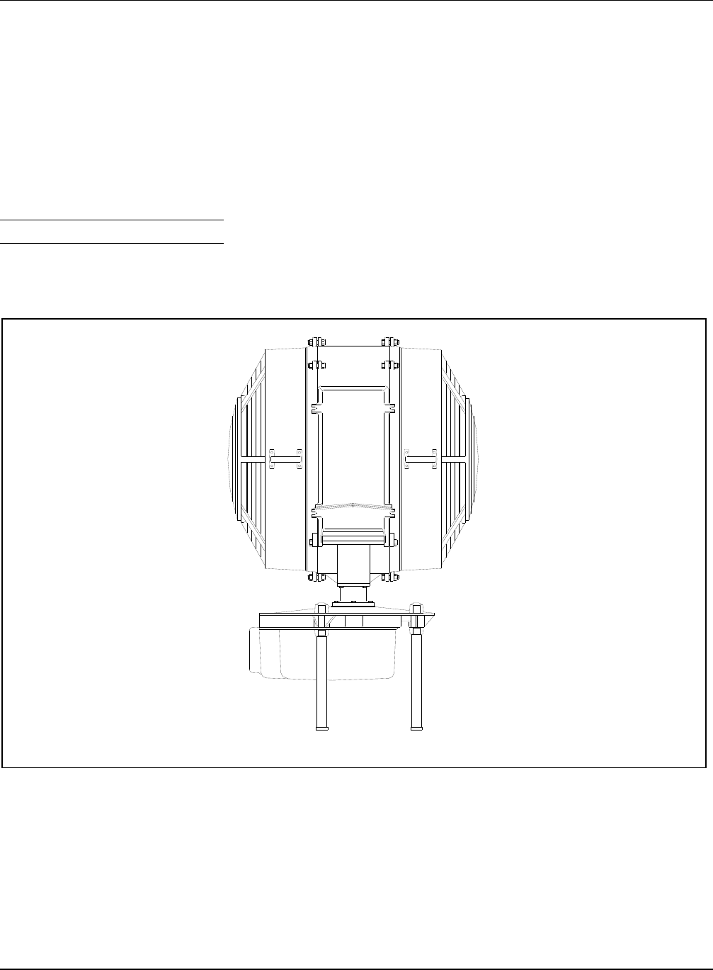
See Figure 1. This section describes the ADB Airfield Solutions L-802A
36-inch (914.4 mm) rotating beacon. The L-802A rotating beacon is
designed to enable pilots to locate the airport from a range up to 80 miles
(49.68 km) and is manufactured to specification AC 150/5345-12C.
Figure 1. L-802A Rotating Beacon
The L-802A rotating beacon consists of the base and the head. The base
houses electrical equipment and the 1/6 HP motor. The head houses the
lamps and the precision filters.
Maintenance and Repair
(contd.)
2. Description

L-802A 36-Inch Airport Rotating Beacon
(1000 Watt Metal Halide Lamp and PRC) Description
2001 ADB Airfield Solutions, LLC
96A0198C Page 6
All rights reserved Issued 5/01
Refer to Table 1 for required equipment that is supplied. Refer to
Table 2 for required equipment that is not supplied. Refer to the Parts
section for ordering information.
Table 1. Required Equipment Supplied
Description Quantity
L-802A rotating beacon 1
Instruction manual 1
Table 2. Required Equipment Not Supplied
Description Quantity
5/811 x 2 in. long (minimum) mounting bolts,
lockwashers and nuts
4
Wrench 1
Voltmeter 1
Insulation tester 1
Lightening rod 1
Torque wrench, 0200 in-lb (022.6 Nt-m) with sockets
and hex drive socket
1
Set of screwdrivers (straight blade and Phillips head) As required
Ground wire for lightening rod As required
Set of pliers As required
Esso #325, or equivalent, silicone grease As required
Cotton cloths As required
Liquid glass cleaner As required
Allen wrenches As required
20 A breaker 1
L-802A Rotating Beacon:
Required Equipment

L-802A 36-Inch Airport Rotating Beacon
(1000 Watt Metal Halide Lamp and PRC) Description
2001 ADB Airfield Solutions, LLC
96A0198C Page 7
All rights reserved Issued 5/01
This subsection describes the specifications for the L-802A rotating
beacons. Refer to the Parts section for part numbers.
Input Voltage
120 Vac
Input Power
1680 W
Lamps
1000 W metal halide
Rated Lamp Life
18,000 hours
Vertical Beam Intensity
Vertical Degrees Minimum Beam Intensity
(White Light)
Candelas (cd)
1 to 2 degrees 37, 500
2 to 8 degrees 75,000
8 to 10 degrees 37,500
Beam Center
The L-802A is factory set at 5 degrees above horizon.
Specifications

L-802A 36-Inch Airport Rotating Beacon
(1000 Watt Metal Halide Lamp and PRC) Description
2001 ADB Airfield Solutions, LLC
96A0198C Page 8
All rights reserved Issued 5/01
Motor
120 V, 60 Hz
Flash Rate
24-30 flashes per minute alternating white and green
Environmental Operating Conditions
The L-802A rotating beacon is designed to operate under the conditions
presented below for temperature, humidity, and rain and hail.
Temperature
-30 to + 55 °C (-22 to +131 °F)
Relative Humidity
Up to 100 %
Rain and Hail
Designed to operate in rain and hail
Paint
Orange
L-802A Glassware
One clear filter, one green filter
Dimensions
See Figures 2 and 3. Below is the beacon height and diameter for head
rotation.
Height:
66 in. (1.676 m)
Diameter required
for head rotation:
48 in. (1.22 m)

L-802A 36-Inch Airport Rotating Beacon
(1000 Watt Metal Halide Lamp and PRC) Description
2001 ADB Airfield Solutions, LLC
96A0198C Page 9
All rights reserved Issued 5/01
Dimensions (contd.)
Figure 2. Mounting Dimensions

L-802A 36-Inch Airport Rotating Beacon
(1000 Watt Metal Halide Lamp and PRC) Description
2001 ADB Airfield Solutions, LLC
96A0198C Page 10
All rights reserved Issued 5/01
Dimensions (contd.)
Figure 3. Overall Mounting Dimensions

L-802A 36-Inch Airport Rotating Beacon
(1000 Watt Metal Halide Lamp and PRC) Installation
2001 ADB Airfield Solutions, LLC
96A0198C Page 11
All rights reserved Issued 5/01
WARNING: Allow only qualified personnel to perform the
following tasks. Observe and follow the safety instructions in
this document and all other related documentation.
This section describes instructions for installing the L-802A 36-inch
rotating beacon.
Handle equipment very carefully to prevent component damage. Note any
exterior damage to the crate that might lead to detection of equipment
damage. If you note any damage to any equipment, file a claim with the
carrier immediately. The carrier may need to inspect the equipment.
The L-802A beacon is designed to be hoisted into place using the mounting
pallet on which the beacon is strapped.
WARNING: Do not attempt to hoist the beacon into place by
attaching the lifting device to the rotating head. This can cause
permanent damage to the drive train.
If you cannot hoist the beacon as an assembled unit, remove the rotating
optical assembly so that you can hoist the beacon into position as two
separate pieces. Whatever method is used, make sure to tether the beacon
so that it will not swing into anything that would damage the outer castings
and lens assembly.
When preparing the beacon for mounting, follow the guidelines below.
See Figure 2. Prior to hoisting, check the triangular bolt hole pattern to
make sure the mounting bolts can be threaded into the hub on the
bottom of the leg without binding. The bolt hole pattern is 16 x 18.5
inches (426.4 x 469.9 mm) for a three-hole mounting pattern.
After the base assembly is in position to be mounted, back off the
upper cap nuts to allow the mounting legs to move freely as the 5/811
mounting bolts are threaded through the mounting platform into the
bottom of the leg.
Once all three bolts are in place, tighten them securely.
3. Installation
Introduction
Unpacking
Hoisting
Mounting Beacon

L-802A 36-Inch Airport Rotating Beacon
(1000 Watt Metal Halide Lamp and PRC) Installation
2001 ADB Airfield Solutions, LLC
96A0198C Page 12
All rights reserved Issued 5/01
The L-802A beacon is designed to operate properly when the axis of
rotation is perpendicular to the ground. A machined reference surface is
cast directly into the base so that the beacon can be leveled in the field. The
leveling surface is on the top side of the base casting adjacent to the bearing
block.
To level the beacon, perform the following procedure:
1. Place a 360-degree bubble level on the leveling surface. Refer to the
flat pad on the top surface of the bedplate.
2. Manipulate the lower retaining nuts on the mounting leg under the base
casting to adjust the beacon position. The beacon should now be level.
3. Tighten the upper cap nuts to secure the beacon.
Refer to Figure 14 in the Wiring Schematics section for the internal wiring
diagram. The L-802A beacon operates on 120 volt, 60 Hz power. The
beacon requires approximately 1680 watts of power under normal
operation. Wiring is accomplished through a removable cover plate on the
bottom of the base casting. The plate serves as the cover on the cast wiring
entrance for the beacon. The plate can be fitted with a suitable connector
that will accept either a 1-inch (25.4 mm) rigid conduit or a 1-inch
(25.4 mm) EMT. The connections for the incoming power are connected to
terminal strip positions 1 and 2.
NOTE: All internal wiring is 12 AWG/600 V. External wiring must be a
minimum of 10 AWG/600 V. All installation wiring should conform to the
applicable sections of the National Electric Code and Local Codes.
The beacon’s lamp is factory adjusted to give maximum intensity at
approximately 5 degrees above horizontal. The beacon uses a 1000 W
metal halide lamp that has a beam vertically broader than the older designs
using an incandescent light source. As a result, the L-802A beacon
provides significant intensity both above and below the nominal setting.
This eliminates the necessity for precise vertical adjustment of the beam.
However, some adjustments may be dictated by local operating conditions.
The beam can be elevated by lowering the lamp, and lowered by raising the
lamp slightly. Reference grooves are provided on the lamp adjustment stem
to verify the elevation setting of the beam. Each groove moves the beam
one degree when aligned with the top edge of the stem bushing that is
welded on top of the lamp support assembly. The five-degree and the ten-
degree settings are stamped on the side of the adjusting stem in a recessed
area.
Leveling Beacon
Wiring
Elevating Lamp

L-802A 36-Inch Airport Rotating Beacon
(1000 Watt Metal Halide Lamp and PRC) Installation
2001 ADB Airfield Solutions, LLC
96A0198C Page 13
All rights reserved Issued 5/01
To elevate the lamp beam, perform the following procedure:
1. See Figure 4. Loosen the hex head screw (3).
2. Raise the lamp (1) to the appropriate reference groove (2) to lower the
beam or lower the lamp to the appropriate reference groove to raise the
beam.
3. Tighten the hex head screw (3).
1
2
3
Figure 4. Elevating Lamp Beam
1. Lamp
2. Reference Grooves
3. 1/420 Hex Head Screw
Elevating Lamp (contd.)

L-802A 36-Inch Airport Rotating Beacon
(1000 Watt Metal Halide Lamp and PRC) Maintenance
2001 ADB Airfield Solutions, LLC
96A0198C Page 14
All rights reserved Issued 5/01
This section provides maintenance information for the L-802A rotating
beacon.
To keep the L-802A rotating beacons operating efficiently, follow a
preventive maintenance schedule. Refer to Table 3. Refer to FAA AC
150/5340-26 for more detailed information.
Table 3. L-802A Rotating Beacon Maintenance
Interval Maintenance Task Action
Daily Check for lamp failure. Replace lamp. Refer to Replacing Lamps in this
section.
Monthly Check for twenty-four flashes per minute
to see if beacon has correct rpm.
If the rpm is incorrect, check the motor and shaft
bearing.
Check for dirty lamp glassware. Clean lamp glassware.
Semi-annually Check for input voltage out of tolerance. Record reading. If the voltage is out of tolerance,
contact the power company or install an
autotransformer. The voltage is out of tolerance if it
is within 10% rated lamp voltage.
Check lightning rod. Tighten loose connections. Check and record
ground resistance.
Check upper bearing Grease, if necessary. Use high quality, low
temperature silicone grease (Esso #325 or
equivalent).
Annually Check to see if the beacon is level. Make the beacon level by using a shim, if
necessary. Check the level in four directions. Refer
to Leveling Beacon in the Installation section.
Check for loose or broken wiring, lugs,
and conduit or deteriorated gaskets.
Repair or renew wiring when needed. Tighten
loose conduit supports and connections. Replace
deteriorated gaskets.
4. Maintenance
Maintenance Schedule

L-802A 36-Inch Airport Rotating Beacon
(1000 Watt Metal Halide Lamp and PRC) Maintenance
2001 ADB Airfield Solutions, LLC
96A0198C Page 15
All rights reserved Issued 5/01
This subsection describes the following maintenance procedures:
replacing lamp
cleaning lenses
cleaning lamp housing
lubricating parts
adjusting slip clutch
Replacing Lamp
Refer to Replacing Lamp in the Repair section.
Cleaning Lenses
Clean lenses periodically with alcohol or glass cleaner and soft cloths.
Wipe dry with a clean soft cloth.
Cleaning Lamp Housing
Remove dust and dirt from the lamp housing using a soft cloth or sponge
with soap and water.
Lubricating Parts
This subsection describes lubrication requirements for the vertical main
shaft, the motor, and the worm gear. Refer to Table 4.
Table 4. Grease Schedule
Interval Part
Periodic Main shaft upper bearing
Twice a year (under normal
conditions)
Main shaft turntable grease fitting
Maintenance Procedures

L-802A 36-Inch Airport Rotating Beacon
(1000 Watt Metal Halide Lamp and PRC) Maintenance
2001 ADB Airfield Solutions, LLC
96A0198C Page 16
All rights reserved Issued 5/01
Vertical Main Shaft
Two ball bearings support the main shaft. The lower bearing is sealed and
permanently lubricated. The upper bearing is packed with grease at the
factory and requires periodic lubrication. An Alumite grease fitting located
on the side of the shaft turntable should also be lubricated, under ordinary
operation, twice a year.
NOTE: Use high quality, low-temperature silicone grease (Esso #325 or
equal).
Motor
The motor is supplied with sealed permanently lubricated bearings.
Worm (Ring) Gear
Apply a small amount of grease (Esso #325 or equivalent) to the worm
gear.
Adjusting Slip Clutch
To adjust the tension on the L-802A beacon slip clutch, perform the
following procedure:
1. See Figure 5. De-energize the beacon and then remove the lower
pan (1) from the beacon.
L-802A 36-Inch Airport Rotating Beacon
(1000 Watt Metal Halide Lamp and PRC) Maintenance
2001 ADB Airfield Solutions, LLC
96A0198C Page 17
All rights reserved Issued 5/01
Adjusting Slip Clutch (contd.)
7
5
4
3
2
6
1
Figure 5. Slip Clutch Adjustment
1. Lower Pan 5. Socket Head Cap Screw
2. Brass Hex Nut 6. Power Entrance Side
3. Third Slot on Shaft 7. Worm Gear
4. Vertical Slot on Shaft
2. From the power entrance side (6) (opposite side from the motor) find
the phenolic worm gear (7). Look above the gear and find the brass
hex nut (2). Look for the 1/420 socket head cap screw (5) located in
the side of the hex nut. If the cap screw is not visible, rotate the beacon
head by hand until the cap screw comes into view.

L-802A 36-Inch Airport Rotating Beacon
(1000 Watt Metal Halide Lamp and PRC) Maintenance
2001 ADB Airfield Solutions, LLC
96A0198C Page 18
All rights reserved Issued 5/01
Adjusting Slip Clutch (contd.)
3. Use an allen hex wrench to remove the cap screw.
4. Use a light source to illuminate the cap screw hole area. Note the
vertical slot (4) that is in the shaft aligned with the cap screw hole.
Four vertical slots are equally spaced around the shaft.
5. Increase the clutch tension by rotating the beacon head, by hand,
counterclockwise until the cap screw hole is aligned with the third
slot (3) past the existing slot.
6. Insert the cap screw back into the hex nut and run the screw through
the nut and into the slot until the screw is in all the way.
7. Reinstall the lower pan.
NOTE: If the head still does not rotate, adjust in two slot increments until
the head begins to rotate.

L-802A 36-Inch Airport Rotating Beacon
(1000 Watt Metal Halide Lamp and PRC) Troubleshooting
2001 ADB Airfield Solutions, LLC
96A0198C Page 19
All rights reserved Issued 5/01
WARNING: Allow only qualified personnel to perform the
following tasks. Observe and follow the safety instructions in
this document and all other related documentation.
WARNING: De-energize the circuit and lock out the circuit or
regulator so that the circuit cannot be energized by remote
means before attempting to service the fixture.
This section contains troubleshooting information. This information covers
only the most common problems that you may encounter. If you cannot
solve the problem with the information given here, contact your local ADB
Airfield Solutions representative for help.
Problem Possible Cause Corrective Action
1. Short lamp life
High lamp voltage Check to see if the correct tap is being used
on the ballast.
Loose connections Tighten connections.
Excessive vibrations Check to make sure the beacon is level.
Refer to Leveling Beacon in the Installation
section. Check the bearing and shaft.
Replace bearing and shaft, if necessary.
Bad socket (arcing) Replace socket.
High voltage spikes Check input voltage and external lightning
arrestor, if installed.
2. Lamp not lighting
Lamp defective Replace lamps. Refer to Replacing Lamp in
the Repair section.
Loose or broken wire Tighten or replace wire.
Power rotary connector defective Replace power rotary connector.
Fuse blown Check and replace fuse, if necessary.
Ballast capacitor defective Check and replace capacitor.
Ballast defective Check and replace ballast, if necessary.
3. Motor not turning
Fuse blown Test fuse. Replace fuse, if necessary.
Motor defective
Replace motor.
Loose or broken wire Tighten or replace wire.
5. Troubleshooting

L-802A 36-Inch Airport Rotating Beacon
(1000 Watt Metal Halide Lamp and PRC) Repair
2001 ADB Airfield Solutions, LLC
96A0198C Page 20
All rights reserved Issued 5/01
Problem Possible Cause Corrective Action
4. Motor runs but
beacon head not
rotating
Seized shaft bearing Replace shaft bearing.
Worm loose, worn or broken
Replace worm.
Worm gear teeth damaged or broken Replace worm gear.
Clutch slipping Adjust clutch pressure. Refer to Adjusting
Slip Clutch in the Maintenance section.
This section provides procedures for replacing the L-802A beacon parts
listed below.
replacing motor
replacing worm or worm gear
replacing slip clutch
replacing power rotary connector (PRC)
replacing lamp
WARNING: Disconnect power to beacon before attempting to
do any work. Failure to de-energize the beacon could result in
serious injury or death by electrocution.
If the motor becomes inoperative and needs to be replaced, refer to the
Parts section for the part number and contact your ADB Airfield Solutions
representative. A service bulletin will be shipped with the motor providing
instructions on removing and remounting the motor. Request Service
Bulletin ALN064.
To remove and replace the motor, perform the following procedure:
1. See Figure 6. Remove the lower pan (5) by unlatching the four over-
the center latches. Place the pan out of the way to facilitate repair
work.
6. Repair
Replacing Motor

L-802A 36-Inch Airport Rotating Beacon
(1000 Watt Metal Halide Lamp and PRC) Repair
2001 ADB Airfield Solutions, LLC
96A0198C Page 21
All rights reserved Issued 5/01
1
2
3
4
5
6
7
Figure 6. Removing Lower Pan
1. Brass Hex Nut with Set Screws 4. Brass Collar 7. Motor
2. Clutch Plate/Worm Gear Assembly 5. PRC
3. Worm and Worm Gear 6. Lower Pan

L-802A 36-Inch Airport Rotating Beacon
(1000 Watt Metal Halide Lamp and PRC) Repair
2001 ADB Airfield Solutions, LLC
96A0198C Page 22
All rights reserved Issued 5/01
2. Locate the terminal block near the motor (7) and disconnect the two
motor leads.
3. Loosen and remove the four hex nuts that secure the motor to the
bedplate.
NOTE: The motor assembly weighs approximately 15 pounds, so take
precautions in handling and removing the motor.
4. See Figure 7. Remove the motor (1) and then remove the worm (5) on
the end of the motor shaft (2) by loosening and removing the hex
nut (7) on the end of the motor shaft.
1
2
3
4
6
7
5
4
5
2
Figure 7. Worm Assembly
1. Motor with Worm Assembly 4. Set Screw 7. Hex Nut
2. Motor Shaft 5. Worm
3. Set Collar 6. Pin
5. Loosen the two allen hex set screws (4) found on the set collar (3).
The set collar is located on the opposite end of the worm toward the
motor. Pull the worm off of the end of the motor shaft. The worm and
set collar are held together with a spring pin (6).
CAUTION: When replacing the set collar, make sure that one
of the set screws (4) is aligned with one of the flats located on
the side of the motor shaft. Once the set screw is positioned
over the flat, tighten the set screw. Failure to tighten this set
screw against the flat on the shaft will allow the
worm to spin free and prevent the beacon head from turning.
Replacing Motor (contd.)
L-802A 36-Inch Airport Rotating Beacon
(1000 Watt Metal Halide Lamp and PRC) Repair
2001 ADB Airfield Solutions, LLC
96A0198C Page 23
All rights reserved Issued 5/01
6. Inspect the worm for nicks or scratches. If the worm profile has been
damaged, dress nick(s) with a fine file or fine silicone sandpaper to
remove burrs.
NOTE: If you need to replace the worm, refer to the Parts section for
ordering information.
7. Separate the set collar from the worm by lightly tapping on the
backside of the worm or wedge a thin flat screwdriver blade between
the two parts and pry them apart.
8. Insert the spring pin in either the new worm on the set collar and then
reassemble the two parts together. Slide the set collar and worm
assembly over the end of the motor shaft until the front face of the
worm is flush with the shoulder on the end of the shaft. Thread the
hex nut back onto the end of the motor shaft.
9. Rotate the collar/worm assembly until the set screws are aligned with
the two flats on the motor shaft and tight the two set screws found in
the set collar against the motor shaft
NOTE: If the worm gear is to be replaced, refer to Replacing Worm
Gear in this section before installing the new motor.
10. Place the motor back on the bedplate by aligning the bolt slots in the
motor mounting foot over the studs in the bedplate. Secure the motor
with hex nuts. Snug the hex nuts but do not tighten the nuts until the
worm on the end of the motor shaft has been aligned with the worm
gear.
CAUTION: If worm is pitched inward or outward about the
tangent point where the worm meshes with the worm gear teeth,
the worm gear will be damaged. Misalignment of the worm and
gear, in time, will cause damage and the beacon will stop
rotating.
11. See Figure 8. Begin the initial worm (1) and worm gear (3) alignment
by first moving the motor so that the worm begins meshing with the
worm gear teeth. Center the worm vertically (4) with the worm gear.
NOTE: If the worm is not centered on the worm gear, then the gear
location must be either adjusted upward or downward until they are
aligned. Refer to Replacing Worm Gear in this section, steps 8 and 9,
for adjusting the clutch plate/worm gear assembly.
Replacing Motor (contd.)

L-802A 36-Inch Airport Rotating Beacon
(1000 Watt Metal Halide Lamp and PRC) Repair
2001 ADB Airfield Solutions, LLC
96A0198C Page 24
All rights reserved Issued 5/01
1
2
3
4
Figure 8. Worm Alignment
1. Worm
2. Worm Perpendicular to Worm Gear
3. Worm Gear
4. Worm Centered Vertically with Centerline of Worm Gear
12. Check the angle that the worm has with the worm gear. Move the
motor until the worm is set perpendicular to the worm gear.
Handtighten the hex nuts slightly to prevent any further movement.
Recheck vertical and horizontal alignment between the worm and the
worm gear. If correct, tighten the hex nuts. Recheck alignment. If
worm is not properly aligned, loosen hex nut and realign hex nuts.
Retighten hex nuts.
Replacing Motor (contd.)

L-802A 36-Inch Airport Rotating Beacon
(1000 Watt Metal Halide Lamp and PRC) Repair
2001 ADB Airfield Solutions, LLC
96A0198C Page 25
All rights reserved Issued 5/01
13. Recheck that all set screws and hex nuts are tight. Apply a small
amount of grease (Esso #325 or equal) to the worm gear.
WARNING: Disconnect power to beacon before attempting to
do any work. Failure to de-energize the beacon could result in
serious injury or death by electrocution.
If the worm or worm gear needs to be replaced, refer to the Parts section
for part numbers and contact your ADB Airfield Solutions representative.
It is recommended that if either one of these parts is replaced, both the
worm and worm gear be replaced at the same time. A service bulletin will
be shipped with the part providing instructions for replacing the worm or
worm gear. Request Service Bulletin ALN064.
NOTE: Replace gear in the maintenance shop. Make sure to remove the
beacon head before turning the unit over.
To replace the worm gear, perform the following procedure:
1. See Figure 6. Remove the lower pan (6) by unlatching the four over-
the-center latches. Place the pan out of the way to facilitate repair
work.
NOTE: While removing all necessary components to get to the worm
gear, note the order and location of the respective parts. Keep all
removed hardware.
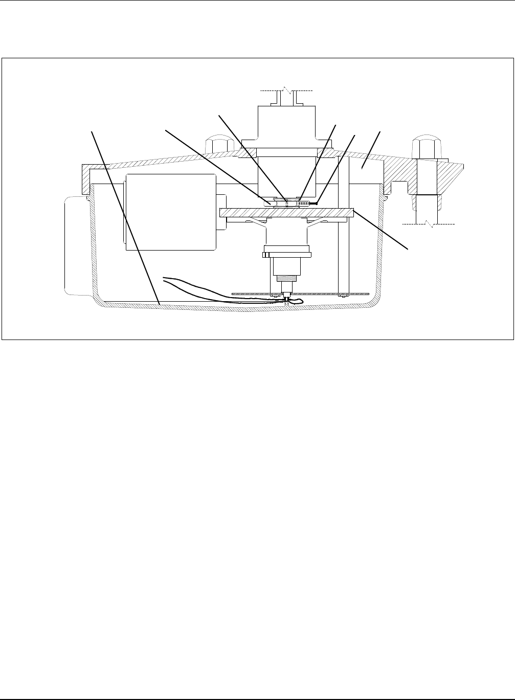
2. See Figure 9. Look underneath the beacon assembly and locate the
PRC mounting plate assembly (3). Reach under the plate and remove
the two 90-degree disconnects (4) from the bottom terminals of the
PRC. Take care in removing the terminals.
Replacing Motor (contd.)
Replacing Worm or Worm
Gear

L-802A 36-Inch Airport Rotating Beacon
(1000 Watt Metal Halide Lamp and PRC) Repair
2001 ADB Airfield Solutions, LLC
96A0198C Page 26
All rights reserved Issued 5/01
1
2
3
4
4
Figure 9. Removing Disconnects
1. Cross-Drilled Holes
2. PRC
3. Mounting Plate Assembly
4. 90-Degree Connectors
Replacing Worm or Worm
Gear (contd.)

L-802A 36-Inch Airport Rotating Beacon
(1000 Watt Metal Halide Lamp and PRC) Repair
2001 ADB Airfield Solutions, LLC
96A0198C Page 27
All rights reserved Issued 5/01
3. Pull straight down to remove the terminal.
CAUTION: Make sure you apply steady straight line pressure
to the quick disconnects when making connections to either end
of the PRC. Do not force disconnects onto the PRC terminals.
Failure to apply straight-line force will induce excessive side
forces that will break off the PRC terminal(s).
Broken terminals cannot be repaired, and the entire PRC must be
replaced.
4. Once both sets of the disconnects have been removed from their
respective PRC terminals, loosen the two large hex nuts that hold the
motor terminal block bracket to the PRC mounting plate. Slide the TB
bracket out from under the hex nuts and allow the bracket to hang
freely or tape it up to get it out of your way.
NOTE: Before proceeding, prevent the spacers on each of the three
threaded standoffs from falling off when the PRC mounting plate is
removed by wrapping a continuous strip of duct tape or electricians
tape around all three spacers that are located between the PRC
mounting plate and the bedplate. Pull the tape tight to help wedge the
spacers against their respective all-thread studs to prevent the spacers
from falling off of the studs when the PRC mounting plate is removed.
Failure to follow these instructions will cause additional work and may
prevent the PRC from being remounted properly.
5. Now remove all three large hex nuts and remove the PRC mounting
plate by applying downward pressure on the PRC plate assembly.
NOTE: The PRC bushing in the plate assembly should remain in the
plate and the PRC should remain attached to the power shaft assembly.
In case the PRC is pulled out, refer to Replacing PRC in this section for
instructions on how to reinstall the PRC.
6. See Figure 6. Remove the clutch plate/worm gear assembly (2) by
locating the large hex brass nut (1) on top of the worm gear (3).
Loosen and remove the long hex socket head cap screw found on the
side of the hex.
7. Loosen the two set screws found on the side of the brass collar (4).
8. Take a barring device. such as a round steel rod or large screwdriver,
and insert through both square slots found on the end of the brass
collar. Turn collar counterclockwise to remove the assembly from the
beacon shaft.
NOTE: This assembly weighs approximately 15 pounds. Take
precautions in handling and removing the assembly.
Replacing Worm or Worm
Gear (contd.)

L-802A 36-Inch Airport Rotating Beacon
(1000 Watt Metal Halide Lamp and PRC) Repair
2001 ADB Airfield Solutions, LLC
96A0198C Page 28
All rights reserved Issued 5/01
9. Once the clutch plate/worm gear assembly is removed, turn the
assembly over and find and remove the #10-32 phillips flat head
screws that secure the worm gear to the collar. Save the screws.
Remove the worn/damaged worm gear from the assembly.
10. Place the new worm gear, with the countersunk screw holes facing up,
onto the shoulder of the collar. Insert the #10-32 flat head screws into
each of the screw holes in the face of the worm gear. First snug the
screws across from each other to prevent the worm gear from being
placed on a bind. Then finish tightening the screws in either a
clockwise or counterclockwise rotation.
NOTE: If the motor is to be replaced, proceed to Replacing Motor in
this section before reinstalling the clutch plate/worm gear assembly.
11. Reinstall the clutch plate/worm gear assembly by performing the
following procedure:
a) Inspect the worm located on the end of the motor shaft, and the
tooth profile for nicks, scratches, and thinned profile.
b) If the worm profile has been damaged, dress nick(s) with a fine file
or fine silicone sandpaper to remove burrs. If the profile has
become thinned, replace the worm. Refer to Replacing Motor in
this section for removal or replacement of the worm.
CAUTION: Do not loosen or remove the large brass hex
nut (1) located on top of the steel clutch plate that is located in
the center of the worm gear. If adjustment to the clutch plate is
required, contact the ADB Airfield Solutions Engineering
Department before proceeding. Improper tension on the clutch
plate will prevent the beacon head from turning.
c) See Figure 9. Note the location of the two taped holes (1) that
have been cross-drilled through the thread found on the end of the
beacon shaft. Align these cross drilled/tapped holes with the
mating cross-drilled holes in the side of the brass collar.
d) Position and slide the assembly over the end of the beacon shaft
and start threading the assembly by hand onto the end of the
beacon shaft. Finish tightening the assembly by inserting the
barring device through the two slots on the end of the brass collar.
Replacing Worm or Worm
Gear (contd.)

L-802A 36-Inch Airport Rotating Beacon
(1000 Watt Metal Halide Lamp and PRC) Repair
2001 ADB Airfield Solutions, LLC
96A0198C Page 29
All rights reserved Issued 5/01
d) As you screw the assembly onto the end of the beacon shaft, check
the alignment of the cross-drilled holes with their mating tapped
holes by using a flashlight to see when the holes are aligned with
each other. Once the holes are aligned, reinstall one of the set
screws. If you cannot insert the set screw, turn the assembly
clockwise or counterclockwise until the screw can be tightened.
e) Once the first set screw is installed properly, install and tighten the
other set screw (located 180 degrees from the first set screw).
f) Reinstall and tighten the long socket head cap screw into the side
of the large brass hex nut. Reconnect the PRC.
CAUTION: Make sure you apply steady straight-line pressure
to the quick disconnects when making connections to either end
of the PRC. Do not force disconnects onto the PRC terminals.
Failure to apply straight-line force will induce excessive side
forces that will break off the PRC terminal(s).
Broken terminals cannot be repaired and the entire PRC must be
replaced.
12. Reinstall the lower pan and latch all four latches.
Before replacing the slip clutch, adjust the slip clutch to increase clutch
resistance. Refer to Adjusting Slip Clutch in the Maintenance section. If
adjusting the slip clutch does not solve the problem, contact your ADB
Airfield Solutions representative before attempting to replace the clutch
assembly.
Remove power to beacon. If beacon has been in operation, allow
sufficient time for the interior temperatures of beacon and the
lamp to cool down before attempting to make any modifications.
Failure to remove power may expose operator to serious harm or
electrocution. Failure to allow lamp and interior surfaces to
cool may cause burns when hot components are touched.
If the power rotary connector (PRC) becomes inoperative and needs to be
replaced, refer to the Parts section for the part number and contact your
ADB Airfield Solutions representative. A service bulletin will be shipped
with the power rotary connector providing instructions on removing and
remounting the motor. Request Service Bulletin ALN074.
NOTE: Before replacing the PRC unlatch and remove the lower bucket
that covers the motor and associated components. Removal of one or both
access doors may be helpful but is not mandatory to facilitate the
replacement of the PRC.
Replacing Worm or Worm
Gear (contd.)
Replacing Slip Clutch
Replacing Power Rotary
Connector

L-802A 36-Inch Airport Rotating Beacon
(1000 Watt Metal Halide Lamp and PRC) Repair
2001 ADB Airfield Solutions, LLC
96A0198C Page 30
All rights reserved Issued 5/01
Removing PRC
To remove a PRC, perform the following procedure:
1. See Figure 10. Open the optical head access door (1) located on the
opposite side where the ballast is located. Unscrew and remove the
lamp from the socket. Place the lamp in safe place to protect it from
being broken.
Do not touch lamp with bare hands. Handling the lamp directly
can shorten lamp life. Use cloth gloves or other appropriate
protection while removing the lamp.
1
Figure 10. Optical Head Access Door (1)

L-802A 36-Inch Airport Rotating Beacon
(1000 Watt Metal Halide Lamp and PRC) Repair
2001 ADB Airfield Solutions, LLC
96A0198C Page 31
All rights reserved Issued 5/01
Removing PRC (contd.)
2. See Figure 11. Open the other access door and remove the screws
securing the ballast heatshield (3) and remove the shield.
1
2
5
4
3
Figure 11. Removing Shield
1. Lamp
2. Ballast
3. Ballast Heatshield
4. PRC Mounting Plate Assembly
5. PRC Wire Leads

L-802A 36-Inch Airport Rotating Beacon
(1000 Watt Metal Halide Lamp and PRC) Repair
2001 ADB Airfield Solutions, LLC
96A0198C Page 32
All rights reserved Issued 5/01
Removing PRC (contd.)
3. Disconnect the two PRC wire leads (5) that come up through the PRC
shaft, at the terminal block. Remove any wire tie wraps that have been
used to dress these two wires.
4. Look underneath the beacon assembly and locate the PRC mounting
plate assembly (4).
5. See Figure 9. Reach under the plate and remove the two 90-degree
disconnects (4) from the bottom terminals of the PRC.
6. Loosen the two large hex nuts that hold the motor terminal block
bracket to the PRC mounting plate. Slide the TB bracket out from
under the hex nuts and allow it to hang freely or tape it up to get out of
your way.
CAUTION: Before proceeding, prevent the spacers on each of
the three threaded standoffs from falling off when the PRC
Mounting Plate is removed by wrapping a continuous strip of
duct tape or electricians tape around all three spacers that are
located between the PRC mounting plate and the
bedplate. Pull the tape tight to help wedge the spacers against
their respective all thread studs to prevent the spacers from
falling off of the studs when the PRC Mounting Plate is
removed. Failure to follow these instructions will cause
additional work and may prevent the PRC from being mounted
properly.
7. Remove all three large hex nuts and remove the PRC mounting plate.
NOTE: The PRC remains attached to the power shaft assembly at this
point.
8. See Figure 12. Loosen the two upper set screws (1) in the side of the
PRC adapter collar that secures the power shaft and PRC adapter collar
together. This allows the power shaft assembly to drop so that the two
small set screws (5) that hold the PRC to the shaft are accessible.
Loosen the two set screws, located 180 degrees apart, and then pull the
PRC out of the plastic bushing found at the end of the shaft.
NOTE: Do not remove the bushing unless it is cracked or damaged.

L-802A 36-Inch Airport Rotating Beacon
(1000 Watt Metal Halide Lamp and PRC) Repair
2001 ADB Airfield Solutions, LLC
96A0198C Page 33
All rights reserved Issued 5/01
Removing PRC (contd.)
5
4
2
1
1
1
3
Figure 12. Power Shaft Assembly
1. Upper Set Screws 3. Collar 5. Set Screws
2. Wire Leads to Ballast 4. Straight Disconnects

L-802A 36-Inch Airport Rotating Beacon
(1000 Watt Metal Halide Lamp and PRC) Repair
2001 ADB Airfield Solutions, LLC
96A0198C Page 34
All rights reserved Issued 5/01
Removing PRC (contd.)
9. Remove the two straight disconnects (4) attached to the upper terminals
of the PRC. Inspect the two straight push-on disconnects for damage
and determine if they must be replaced. If disconnects must be
replaced, cut them off the wires and install new disconnects.
Disconnects must be crimped onto the ends of the wire.
Replacing PRC
WARNING: The PRC must be installed with the symbol
UP
pointing up to operate. Failure to install the PRC upright will
cause the PRC to fail.
Ensure you apply steady straight line pressure to the quick
disconnects when making connections to either end of the Power
Rotary Connector (PRC). Do not force disconnects onto the
PRC terminals. Failure to apply straight-line force will induce
excessive side forces that will break off the PRC terminal(s).
Broken terminals can not be repaired and the entire PRC must be
replaced.
To replace a PRC, perform the following procedure:
1. After pulling the two wire leads down through the power shaft
assembly to create a small amount of slack in the wires, be sure that the
PRC has been turned so that it is orientated with the imprinted
UP
symbol, found on the side of the PRC body, is pointing up.
CAUTION: When installing the two straight disconnects to the
PRC terminals, note that the PRC terminals are off - centered in
the sleeve and that the insulation sleeve on the disconnect has a
flat side. Orientate the flat side of insulation sleeve on the first
disconnect is facing toward the other terminal space on the PRC.
Install the second disconnect so that its flat side is facing the
other terminal spade. Failure to follow these instruction will
could result in breaking off one or both of the terminal spades
from the PRC. Broken terminal spades cannot be repaired.

L-802A 36-Inch Airport Rotating Beacon
(1000 Watt Metal Halide Lamp and PRC) Repair
2001 ADB Airfield Solutions, LLC
96A0198C Page 35
All rights reserved Issued 5/01
Replacing PRC (contd.)
2. Push, with straight-line force, the two straight disconnects on to the
terminals found on the top of the PRC. Once terminals are attached,
push the PRC back into the bushing found on the inside of the power
shaft.
3. Tighten the two set screws to secure the PRC to the power shaft.
CAUTION: Failure to make set screws tight will allow the
power shaft slip and cause the wires connected to the PRC to
twist and then break causing power to be terminated to the lamp.
However, do not overtighten set screws. Overtightening will
crack outer PRC terminal sleeve and the epoxy poured around
the terminals. Damage to either/both the sleeve and terminals
will cause the PRC to fail overtime.
4. See Figure 12. Push the power shaft assembly back up inside the
collar. Retighten the two set screws found in the side of the collar to
secure the shaft to the collar.
CAUTION: Ensure that the set screws in the collar are tight.
Failure to make set screws tight will allow the Power Shaft slip
and cause the wires connected to the PRC to twist and then
break causing power to be terminated to the lamp.
5. Remove the slack in the wires by gently pulling on the wires on the
opposite end of the PSA.
6. See Figure 11. Turn the plate so that the shoulder on the PRC bushing
(pre-installed in the plate at the factory) will be against the PRC when
the plate is installed. Slip the PRC mounting plate assembly (4) over
the three all-thread studs and secure with the three hex nuts. Thread
the nuts on just enough to keep the plate from falling off the studs.
7. Bring the mounting plate up against the PRC and push the bushing
onto the PRC. The fit between the PRC bushing ID is a snug fit. Once
the PRC is seated into the bushing, finger tighten the three hex nuts up
against the bottom of the plate. Remove the duct tape from around the
three spacers.
NOTE: To install the PRC mounting plate, you may need to adjust the
PRC Shaft. When the PRC is installed properly in the end of the PRC
shaft and the two set screws are tightened, the location of the set
screws will be either at the very end of the beacon shaft or can be
slightly up inside of the shaft.

L-802A 36-Inch Airport Rotating Beacon
(1000 Watt Metal Halide Lamp and PRC) Repair
2001 ADB Airfield Solutions, LLC
96A0198C Page 36
All rights reserved Issued 5/01
Replacing PRC (contd.)
8. If required, push up the PRC shaft assembly. This is accomplished by
loosening the two 1/4-20 hex head set screws used hold the shaft in the
large collar on the other end of the shaft located in the beacon head and
push the shaft assembly upward.
9. Reinstall the terminal block mounting bracket onto the two appropriate
studs by loosening the hex nuts just enough so that you can slip bracket
between the hex nut and the underside of the mounting plate.
CAUTION: Do not place the terminal block bracket between
the top of the plate and the spacer. Failure to follow this
instruction will result in placing the PRC on a bind and will
prevent it from turning.
10. Tighten all three hex nuts so that the PRC mounting plate is secure
against each of the three Spacers.
11. Reinstall the two 90-degree disconnects to the terminals on the bottom
of the PRC. The two 90-degree disconnects must be turned in opposite
direction. See Figure 13 before pushing them onto the PRC terminals.
Failure to turn them in opposite directions may cause at least one of the
terminals on the PRC to break off.
CAUTION: Make sure you apply steady straight line pressure
to the quick disconnects when making connections to either end
of the PRC. Do not force disconnects onto the PRC terminals.
Failure to apply straight-line force will induce excessive side
forces that will break off the PRC terminal(s).
Broken terminals cannot be repaired and the entire PRC must be
replaced.
12. See Figure 6. Return to the beacon head and reinstall the lamp and
reconnect the two PRC leads to the terminal block in the beacon head.
Reinstall the ballast shield and tighten hardware.
CAUTION: Do not touch lamp with bare hands. Handling the
lamp directly can shorten lamp life. Use cloth gloves or other
appropriate protection while removing the lamp.

L-802A 36-Inch Airport Rotating Beacon
(1000 Watt Metal Halide Lamp and PRC) Repair
2001 ADB Airfield Solutions, LLC
96A0198C Page 37
All rights reserved Issued 5/01
Replacing PRC (contd.)
13. Recheck all wiring connections and make sure all hardware is tight.
Use wire tie wraps and dress all wires. Make sure all wires are not in
contact with any sharp edges. Check fuses to ensure they have not
blown.
14. Reinstall the bucket and any access doors that were removed.
15. Energize beacon to verify operation. The metal halide lamp has a cold
start strike of approximately 5 minutes before it reaches full intensity.
If the lamp needs to be replaced, refer to the Parts section for the part
number and contact your ADB Airfield Solutions representative. A service
bulletin will be shipped with the lamp providing instructions on replacing
the lamp. Request Service Bulletin ALN074.
WARNING: The filter and lamp temperatures can be in excess
of 375 °F (191 °C). Turn the beacon off and allow to cool down
for at least one hour before touching filters or lamps. Failure to
observe this warning may result in personal injury or equipment
damage.
WARNING: Metal halide lamps can cause serious burn and
eye inflammation from short wave ultra-violet radiation if the
outer envelope of the lamp is broken or punctured when the
lamp is energized. Do not remain for more than a few minutes
near the
lamps when they are energized unless adequate shielding or other safety
precautions are used.
CAUTION: Wear clean, lint-free gloves while handling a new
lamp. Touching the lamp with bare fingers may seriously
shorten lamp life. If the lamp has been touched, wipe it
carefully with a piece of lens-cleaning tissue or similar material
moistened
with isopropol alcohol.
Replacing Lamp

L-802A 36-Inch Airport Rotating Beacon
(1000 Watt Metal Halide Lamp and PRC) Parts
2001 ADB Airfield Solutions, LLC
96A0198C Page 38
All rights reserved Issued 5/01
To order parts, call ADB Airfield Solutions Customer Service or your local
representative. Use this four-column parts list, and the accompanying
illustration, to describe and locate parts correctly.
The Item column numbers correspond to the numbers that identify parts in
illustrations following each parts list. NS (not shown) indicates that a listed
part is not illustrated.
The Description column gives the part name, as well as its dimensions and
other characteristics when appropriate. Indentions show the relationships
between assemblies, subassemblies, and parts.
The Part Number column gives the ADB Airfield Solutions part number.
Item Description Part Number Note
NS Assembly
xxxxxxxx A
T1 Assembly
Part xxxxxxxx
Part
xxxxxxxx
The Note column contains letters that refer to notes at the end of each parts
list. Notes contain special ordering information.
7. Parts
Using the Illustrated Parts
List

L-802A 36-Inch Airport Rotating Beacon
(1000 Watt Metal Halide Lamp and PRC) Parts
2001 ADB Airfield Solutions, LLC
96A0198C Page 39
All rights reserved Issued 5/01
Refer to Table 5 to determine the part number for a particular L-802A
rotating beacon.
Table 5. L-802A Part Numbers
L-802A Rotating Beacon Part Number
With L-810 obstruction light 44D2069-410
Without L-810 obstruction light 44D2069-420
See Figure 13.
Item Description Part Number Note
1 Filter lens clip
60C2045
2 Doublet
Clear inner doublet 63A0603
Green inner doublet
63A0630
3 Ballast, with capacitor
35A0490
4 Upper filter shield
60B2243
5 Spider support for inner doublet
62D0649
6 1000 W metal halide lamp
48A0337
7 Lamp adjustment stem 60B2274
8 Lens sector fastener for 20-inch (508 mm) lens
62D0651
9 Lower filter shield
60B2243
10 Lens sector fastener for 36-inch (914.4 mm) lens
62D0650
11 Outer sectors
30-degree outer sectors, left 63A0632
30-degree outer sectors, right
63A0631
12 Clear outer doublet
63A0604
13 Lamp socket 49A0136
14 Upper bearing
75A0022
15 Shaft assembly 60C1189
L-802A Rotating Beacon Part
Numbering System
L-802A Rotating Beacon
Parts List

L-802A 36-Inch Airport Rotating Beacon
(1000 Watt Metal Halide Lamp and PRC) Parts
2001 ADB Airfield Solutions, LLC
96A0198C Page 40
All rights reserved Issued 5/01
Item Description Part Number Note
16 Lower bearing
75A0021
17 Cap nut
62C0625
18 Retaining nut
62C0627
19 Power rotary connector (PRC)
76A0012
20 Worm, brass
68A0014
21 Worm (ring) gear, phenolic
68A0012
22 Motor
69C0012
23 Lamp socket assembly 44B4653
24 Lamp socket base
60C2010
25 Shaft bushing
60B2193
26 Power shaft coupling 60B2194
27 PRC power shaft 60B2196
28 Straight disconnect, insulated
70A0492
29 Power rotary bushing, installed in the PRC end of the shaft
60B2192
30 Power rotary connector (PRC) bushing for mounting plate
60B2277
31 Right angle (90 degree) disconnect, insulated 70A0329
32 PRC mounting plate 60B2195
NS Fuse, 5A, motor
47A0130
NS Fuse, 15A, lamp
47A0175
NS L-810 single obstruction light assembly
44C1005-1
NS L-810 lamp 69 W 120 Vac
48A0009
NS L-810 lens, red
63A0149
NS L-810 lens gasket 63B0015
NS: Not Shown
L-802A Rotating Beacon
Parts List (contd.)

L-802A 36-Inch Airport Rotating Beacon
(1000 Watt Metal Halide Lamp and PRC) Parts
2001 ADB Airfield Solutions, LLC
96A0198C Page 41
All rights reserved Issued 5/01
1
2
3
4
5
6
7
8
9
10
11, 12
13
14
15
16
17
18
19
20, 21
22
23
24
Figure 13. L-802A 36-Inch Rotating Beacon (Part 1 of 2)
L-802A Rotating Beacon
Parts List (contd.)

L-802A 36-Inch Airport Rotating Beacon
(1000 Watt Metal Halide Lamp and PRC) Parts
2001 ADB Airfield Solutions, LLC
96A0198C Page 42
All rights reserved Issued 5/01
32
31
31
30
29
28
28
27
26
25
Figure 13. L-802A 36-Inch Rotating Beacon (Part 2 of 2)

L-802A 36-Inch Airport Rotating Beacon
(1000 Watt Metal Halide Lamp and PRC) Wiring Schematics
2001 ADB Airfield Solutions, LLC
96A0198C Page 43
All rights reserved Issued 5/01
See Figure 14. This section provides internal wiring schematics for the L-
802A rotating beacon.
Figure 14. Internal Wiring Schematic
8. Wiring Schematics
