
Manufacturer reserves the right to discontinue, or change at any time, specifications or designs without notice and without incurring obligations.
Catalog No. 04-53300125-01 Printed in U.S.A. Form 30RB-7T Pg 1 1115 1-14 Replaces: 30RB-6T
Controls, Start-Up, Operation, Service
and Troubleshooting
CONTENTS
Page
SAFETY CONSIDERATIONS . . . . . . . . . . . . . . . . . . . . . . . 2,3
GENERAL . . . . . . . . . . . . . . . . . . . . . . . . . . . . . . . . . . . . . . . . . 3-5
Conventions Used in This Manual . . . . . . . . . . . . . . . . . . .3
Basic Control Usage. . . . . . . . . . . . . . . . . . . . . . . . . . . . . . . . .4
• SCROLLING MARQUEE DISPLAY
• ACCESSORY NAVIGATOR™ DISPLAY MODULE
CONTROLS. . . . . . . . . . . . . . . . . . . . . . . . . . . . . . . . . . . . . . . 6-43
General. . . . . . . . . . . . . . . . . . . . . . . . . . . . . . . . . . . . . . . . . . . . . .6
Main Base Board (MBB) . . . . . . . . . . . . . . . . . . . . . . . . . . . . .6
Scroll Protection Module (SPM) . . . . . . . . . . . . . . . . . . . . .8
Electronic Expansion Valve (EXV) Board . . . . . . . . . . . .9
Fan Boards . . . . . . . . . . . . . . . . . . . . . . . . . . . . . . . . . . . . . . . . .10
Reverse Rotation Board . . . . . . . . . . . . . . . . . . . . . . . . . . . .15
• DIAL SETTINGS
• PHASE REVERSAL PROTECTION
• PHASE LOSS AND UNDER-VOLTAGE
PROTECTION
Enable-Off-Remote Contact Switch . . . . . . . . . . . . . . . . .15
Emergency On/Off Switch . . . . . . . . . . . . . . . . . . . . . . . . . .15
Energy Management Module (EMM) . . . . . . . . . . . . . . . .15
Energy Management Module
Heat Reclaim (EMM HR) . . . . . . . . . . . . . . . . . . . . . . . . . .16
Local Equipment Network . . . . . . . . . . . . . . . . . . . . . . . . . .17
Board Addresses . . . . . . . . . . . . . . . . . . . . . . . . . . . . . . . . . . .17
Control Module Communication . . . . . . . . . . . . . . . . . . . .17
• RED LED
• GREEN LED
• YELLOW LED
Carrier Comfort Network
®
(CCN) Interface . . . . . . . . . .17
Configuration Options. . . . . . . . . . . . . . . . . . . . . . . . . . . . . .18
• MINIMUM LOAD CONTROL
• RAMP LOADING
• MINUTES OFF TIME
Dual Chiller Control . . . . . . . . . . . . . . . . . . . . . . . . . . . . . . . .18
Capacity Control . . . . . . . . . . . . . . . . . . . . . . . . . . . . . . . . . . .21
• BRINE CHILLER OPERATION
• CAPACITY CONTROL OVERRIDES
Head Pressure Control . . . . . . . . . . . . . . . . . . . . . . . . . . . . .25
• STANDARD UNIT
• LOW AMBIENT TEMPERATURE HEAD PRESSURE
CONTROL OPTION
High-Efficiency Variable
Condenser Fans (HEVCF) . . . . . . . . . . . . . . . . . . . . . . . . .27
Cooler Pump Control . . . . . . . . . . . . . . . . . . . . . . . . . . . . . . .29
Machine Control Methods . . . . . . . . . . . . . . . . . . . . . . . . . .30
• SWITCH CONTROL
• TIME SCHEDULE
• CCN CONTROL
• UNIT RUN STATUS
Cooling Set Point Selection . . . . . . . . . . . . . . . . . . . . . . . .31
• SET POINT 1
• SET POINT 2
• 4 TO 20 mA INPUT
• DUAL SWITCH
• SET POINT OCCUPANCY
Temperature Reset . . . . . . . . . . . . . . . . . . . . . . . . . . . . . . . . .32
Page
Demand Limit . . . . . . . . . . . . . . . . . . . . . . . . . . . . . . . . . . . . . . 40
• SWITCH CONTROLLED
• EXTERNALLY POWERED (4 to 20 mA Controlled)
• CCN CONTROLLED
Remote Alarm and Alert Relays . . . . . . . . . . . . . . . . . . . . 42
Broadcast Configuration . . . . . . . . . . . . . . . . . . . . . . . . . . .42
Alarm Control . . . . . . . . . . . . . . . . . . . . . . . . . . . . . . . . . . . . . . 42
PRE-START-UP . . . . . . . . . . . . . . . . . . . . . . . . . . . . . . . . . . . .43
System Check. . . . . . . . . . . . . . . . . . . . . . . . . . . . . . . . . . . . . . 43
START-UP. . . . . . . . . . . . . . . . . . . . . . . . . . . . . . . . . . . . . . . 43-45
Actual Start-Up . . . . . . . . . . . . . . . . . . . . . . . . . . . . . . . . . . . . .43
Operating Limitations . . . . . . . . . . . . . . . . . . . . . . . . . . . . . .44
• TEMPERATURES
• VOLTAGE
• MINIMUM FLUID LOOP VOLUME
• FLOW RATE REQUIREMENTS
OPERATION. . . . . . . . . . . . . . . . . . . . . . . . . . . . . . . . . . . . . 45-52
Sequence of Operation . . . . . . . . . . . . . . . . . . . . . . . . . . . . .45
Dual Chiller Sequence of Operation . . . . . . . . . . . . . . . .45
Operating Modes . . . . . . . . . . . . . . . . . . . . . . . . . . . . . . . . . . . 46
Optional Heat Reclaim Module . . . . . . . . . . . . . . . . . . . . .48
SERVICE . . . . . . . . . . . . . . . . . . . . . . . . . . . . . . . . . . . . . . . . 53-61
Electronic Expansion Valve (EXV) . . . . . . . . . . . . . . . . . .53
• EXV TROUBLESHOOTING PROCEDURE
Cooler. . . . . . . . . . . . . . . . . . . . . . . . . . . . . . . . . . . . . . . . . . . . . .56
• FREEZE PROTECTION
• LOW FLUID TEMPERATURE
• LOSS OF FLUID FLOW PROTECTION
• TUBE PLUGGING
• RETUBING
• TIGHTENING COOLER HEAD BOLTS
• CHILLED WATER FLOW SWITCH
RTPF Condenser Coil Maintenance and Cleaning
Recommendations . . . . . . . . . . . . . . . . . . . . . . . . . . . . . . .57
• REMOVE SURFACE LOADED FIBERS
• PERIODIC CLEAN WATER RINSE
• ROUTINE CLEANING OF COIL SURFACES
MCHX Condenser Coil Maintenance and Cleaning
Recommendations . . . . . . . . . . . . . . . . . . . . . . . . . . . . . . .60
Condenser Fans. . . . . . . . . . . . . . . . . . . . . . . . . . . . . . . . . . . .60
Refrigerant Circuit. . . . . . . . . . . . . . . . . . . . . . . . . . . . . . . . . . 60
• LEAK TESTING
• REFRIGERANT CHARGE
Safety Devices . . . . . . . . . . . . . . . . . . . . . . . . . . . . . . . . . . . . .60
• COMPRESSOR PROTECTION
• CRANKCASE HEATERS
Relief Devices . . . . . . . . . . . . . . . . . . . . . . . . . . . . . . . . . . . . . .60
• HIGH-SIDE PROTECTION
• LOW-SIDE PROTECTION
Compressors. . . . . . . . . . . . . . . . . . . . . . . . . . . . . . . . . . . . . . . 61
• COMPRESSOR REPLACEMENT
• OIL CHARGE
• SYSTEM BURNOUT CLEANUP PROCEDURE
MAINTENANCE. . . . . . . . . . . . . . . . . . . . . . . . . . . . . . . . . . 61,62
Recommended Maintenance Schedule . . . . . . . . . . . . .61
AquaSnap
®
30RB060-390 Air-Cooled Chillers and
30RB080-390 Air-Cooled Chillers with
Greenspeed
®
Intelligence

2
CONTENTS (cont)
Page
TROUBLESHOOTING . . . . . . . . . . . . . . . . . . . . . . . . . . . 62-93
Alarms and Alerts . . . . . . . . . . . . . . . . . . . . . . . . . . . . . . . 62
• DIAGNOSTIC ALARM CODES AND POSSIBLE
CAUSES
Sensors. . . . . . . . . . . . . . . . . . . . . . . . . . . . . . . . . . . . . . . . . . . . 78
Thermistors. . . . . . . . . . . . . . . . . . . . . . . . . . . . . . . . . . . . . . . . 78
• COOLER ENTERING FLUID SENSOR
• COOLER LEAVING FLUID SENSOR
• DUAL CHILLER LWT
• COMPRESSOR SUCTION GAS TEMPERATURE
• OUTDOOR AIR TEMPERATURE
• CONDENSER LEAVING FLUID SENSOR
• CONDENSER ENTERING FLUID SENSOR
• SUBCOOLED CONDENSER GAS TEMPERATURE
• REMOTE SPACE TEMPERATURE
Transducers . . . . . . . . . . . . . . . . . . . . . . . . . . . . . . . . . . . . . . . 79
Service Test . . . . . . . . . . . . . . . . . . . . . . . . . . . . . . . . . . . . . . . 83
APPENDIX A — LOCAL DISPLAY TABLES . . . . . 94-106
APPENDIX B — CCN TABLES. . . . . . . . . . . . . . . . . 107-121
APPENDIX C — CCN ALARM DESCRIPTION . . 122-125
APPENDIX D — R-410A PRESSURE VS.
TEMPERATURE CHART . . . . . . . . . . . . . . . . . . . . . . . . 126
APPENDIX E — MAINTENANCE SUMMARY AND
LOG SHEETS . . . . . . . . . . . . . . . . . . . . . . . . . . . . . . . 127-130
APPENDIX F — BACNET COMMUNICATION
OPTION . . . . . . . . . . . . . . . . . . . . . . . . . . . . . . . . . . . . . 131-142
APPENDIX G — SIEMENS OR SCHNEIDER LOW
AMBIENT DRIVES . . . . . . . . . . . . . . . . . . . . . . . . . 143-148
INDEX. . . . . . . . . . . . . . . . . . . . . . . . . . . . . . . . . . . . . . . . . 149,150
START-UP CHECKLIST FOR 30RB
LIQUID CHILLER . . . . . . . . . . . . . . . . . . . . . . . CL-1 to CL-10
SAFETY CONSIDERATIONS
Installing, starting up, and servicing this equipment can be
hazardous due to system pressures, electrical components, and
equipment location (roof, elevated structures, etc.). Only
trained, qualified installers and service mechanics should
install, start up, and service this equipment. When working on
this equipment, observe precautions in the literature, and on
tags, stickers, and labels attached to the equipment, and any
other safety precautions that apply. Follow all safety codes.
Wear safety glasses and work gloves. Use care in handling,
rigging, and setting this equipment, and in handling all electri-
cal components.
WARNING
Electrical shock can cause personal injury and death. Shut
off all power to this equipment during installation. There
may be more than one disconnect switch. Tag all discon-
nect locations to alert others not to restore power until work
is completed.
WARNING
DO NOT VENT refrigerant relief valves within a building.
Outlet from relief valves must be vented outdoors in
accordance with the latest edition of ANSI/ASHRAE
(American National Standards Institute/American Society
of Heating, Refrigerating and Air-Conditioning Engineers)
15 (Safety Code for Mechanical Refrigeration). The
accumulation of refrigerant in an enclosed space can
displace oxygen and cause asphyxiation. Provide adequate
ventilation in enclosed or low overhead areas. Inhalation of
high concentrations of vapor is harmful and may cause
heart irregularities, unconsciousness or death. Misuse can
be fatal. Vapor is heavier than air and reduces the amount
of oxygen available for breathing. Product causes eye and
skin irritation. Decomposition products are hazardous.
WARNING
DO NOT USE TORCH to remove any component. System
contains oil and refrigerant under pressure.
To remove a component, wear protective gloves and gog-
gles and proceed as follows:
a. Shut off electrical power to unit.
b. Recover refrigerant to relieve all pressure from sys-
tem using both high-pressure and low pressure ports.
c. Traces of vapor should be displaced with nitrogen
and the work area should be well ventilated. Refrig-
erant in contact with an open flame produces toxic
gases.
d. Cut component connection tubing with tubing cutter
and remove component from unit. Use a pan to catch
any oil that may come out of the lines and as a gage
for how much oil to add to the system.
e. Carefully unsweat remaining tubing stubs when nec-
essary. Oil can ignite when exposed to torch flame.
Failure to follow these procedures may result in personal
injury or death.

3
GENERAL
This publication contains Controls, Operation, Start-Up,
Service and Troubleshooting information for the 30RB060-390
air-cooled liquid chillers with electronic controls. The 30RB
chillers are equipped with ComfortLink controls and electronic
expansion valves.
NOTE: Unit sizes 315-390 are modular units that are shipped
in separate sections as modules A or B as noted in position 8 of
the unit model number. Installation directions specific to these
units are noted in these instructions. For modules 315A, 315B,
330A, 330B, 345A, 345B, and 360B, follow all general
instructions as noted for unit sizes 30RB160,170. For modules
360A, 390A, and 390B, follow instructions for 30RB190. See
Table 1 for a listing of unit sizes and modular combinations.
NOTE: The nameplate for modular units contains only the first
two digits in the model number. For example, 315A and 315B
nameplates read 31A and 31B.
Table 1 — Modular Unit Combinations
Conventions Used in This Manual — The follow-
ing conventions for discussing configuration points for the
local display (scrolling marquee or Navigator™ accessory)
will be used in this manual.
Point names will be written with the mode name first, then
any sub-modes, then the point name, each separated by an
arrow symbol (. Names will also be shown in bold
and italics. As an example, the Lead/Lag Circuit Select Point,
which is located in the Configuration mode, Option sub-mode,
would be written as Configuration OPTNLLCS.
This path name will show the user how to navigate through
the local display to reach the desired configuration. The user
would scroll through the modes and sub-modes using the
and keys. The arrow symbol in the path name repre-
sents pressing to move into the next level of the
menu structure.
When a value is included as part of the path name, it will be
shown at the end of the path name after an equals sign. If the
value represents a configuration setting, an explanation will
CAUTION
This unit uses a microprocessor control system. Do not
short or jumper between terminations on circuit boards or
modules; control or board failure may result.
Be aware of electrostatic discharge (static electricity) when
handling or making contact with circuit boards or module
connections. Always touch a chassis (grounded) part to dis-
sipate body electrostatic charge before working inside con-
trol center.
Use extreme care when handling tools near boards and
when connecting or disconnecting terminal plugs. Circuit
boards can easily be damaged. Always hold boards by the
edges and avoid touching components and connections.
This equipment uses, and can radiate, radio frequency
energy. If not installed and used in accordance with the
instruction manual, it may cause interference to radio com-
munications. It has been tested and found to comply with
the limits for a Class A computing device pursuant to Inter-
national Standard in North America EN 61000-2/3 which
are designed to provide reasonable protection against such
interference when operated in a commercial environment.
Operation of this equipment in a residential area is likely to
cause interference, in which case the user, at his own
expense, will be required to take whatever measures may
be required to correct the interference.
Always store and transport replacement or defective boards
in anti-static shipping bag.
CAUTION
To prevent potential damage to heat exchanger, always run
fluid through heat exchanger when adding or removing
refrigerant charge. Use appropriate brine solutions in cooler
fluid loop to prevent the freezing of heat exchanger,
optional hydronic section and/or interconnecting piping
when the equipment is exposed to temperatures below 32 F
(0° C). Proof of flow switch and strainer are factory
installed on all models. Do NOT remove power from this
chiller during winter shutdown periods without taking pre-
caution to remove all water from heat exchanger and
optional hydronic system. Failure to properly protect the
system from freezing may constitute abuse and may void
warranty.
CAUTION
Compressors and optional hydronic system pumps require
specific rotation. Check reverse rotation board. If lower
(red) LED is blinking, the phase sequence is incorrect.
Swap any two incoming power leads to correct condenser
fan rotation before starting any other motors. Operating the
unit without verifying proper phasing could result in equip-
ment damage.
CAUTION
Refrigerant charge must be removed slowly to prevent loss
of compressor oil that could result in compressor failure.
CAUTION
Puron
®
refrigerant (R-410A) systems operate at higher
pressures than standard R-22 systems. Do not use R-22 ser-
vice equipment or components on Puron refrigerant equip-
ment. If service equipment is not rated for Puron
refrigerant, equipment damage or personal injury may
result.
CAUTION
DO NOT re-use compressor oil or any oil that has been
exposed to the atmosphere. Dispose of oil per local codes
and regulations. DO NOT leave refrigerant system open to
air any longer than the actual time required to service the
equipment. Seal circuits being serviced and charge with
dry nitrogen to prevent oil contamination when timely
repairs cannot be completed. Failure to follow these proce-
dures may result in damage to equipment.
UNIT SIZE MODULE A MODULE B
30RB315 30RB160 30RB160
30RB330 30RB170 30RB160
30RB345 30RB170 30RB170
30RB360 30RB190 30RB170
30RB390 30RB190 30RB190
ENTER

4
be shown in parenthesis after the value. As an example,
ConfigurationOPTNLLCS = 1 (Circuit A leads).
Pressing the and keys simultaneously
will scroll an expanded text description of the point name or
value across the display. The expanded description is shown in
the local display tables but will not be shown with the path
names in text.
The CCN (Carrier Comfort Network
®
) point names are also
referenced in the local display tables for users configuring the
unit with CCN software instead of the local display. The CCN
tables are located in Appendix B of the manual.
Basic Control Usage
SCROLLING MARQUEE DISPLAY — The scrolling mar-
quee display is the standard interface display to the ComfortLink
control system for 30RB units. The display has up and down ar-
row keys, an key, and an key. These keys
are used to navigate through the different levels of the display
structure. Press the key until the highest operating
level is displayed to move through the top 11 mode levels indi-
cated by LEDs (light-emitting diodes) on the left side of the dis-
play. See Fig. 1.
Once within a mode or sub-mode, pressing the
and keys simultaneously will put the scrolling
marquee display into expanded text mode where the full mean-
ing of all sub-modes, items and their values can be displayed
for the current selection. Press the and
keys to return the scrolling marquee display to its default menu
of rotating display items (those items in Run StatusVIEW).
In addition, the password will be disabled, requiring that it be
entered again before changes can be made to password
protected items. Press the key to exit out of the ex-
panded text mode.
NOTE: When the Language Selection (Configuration
DISPLANG), variable is changed, all appropriate display
expansions will immediately change to the new language. No
power-off or control reset is required when reconfiguring
languages.
When a specific item is located, the item name alternates
with the value. Press the key at a changeable item
and the value will be displayed. Press again and the
value will begin to flash indicating that the value can be
changed. Use the up and down arrow keys to change the value,
and confirm the value by pressing the key.
Changing item values or testing outputs is accomplished in
the same manner. Locate and display the desired item. Press
so that the item value flashes. Use the arrow keys to
change the value or state and press the key to accept
it. Press the key to return to the next higher level of
structure. Repeat the process as required for other items.
Items in the Configuration and Service Test modes are pass-
word protected. The words ‘PASS’ and ‘WORD’ will alternate
on the display when required. The default password is 0111.
Press and the 1111 password will be displayed. Press
again and the first digit will begin to flash. Use the
arrow keys to change the number and press to accept
the digit. Continue with the remaining digits of the password.
The password can only be changed through CCN operator in-
terface software such as ComfortWORKS
®
, ComfortVIEW™
and Service Tool.
See Table 2 and Appendix A for further details.
ACCESSORY NAVIGATOR™ DISPLAY MODULE —
The Navigator module provides a mobile user interface to the
ComfortLink control system, which is only available as a field-
installed accessory. The display has up and down arrow keys,
an key, and an key. These keys are used
to navigate through the different levels of the display structure.
Press the key until ‘Select a Menu Item’ is dis-
played to move through the top 11 mode levels indicated by
LEDs on the left side of the display. See Fig. 2.
Once within a Mode or sub-mode, a “>” indicates the cur-
rently selected item on the display screen. Pressing the
and keys simultaneously will put the Nav-
igator module into expanded text mode where the full meaning
of all sub-modes, items and their values can be displayed. Press-
ing the and keys when the display says
‘Select Menu Item’ (Mode LED level) will return the Navigator
module to its default menu of rotating display items (those items
in Run StatusVIEW). In addition, the password will be dis-
abled, requiring that it be entered again before changes can be
made to password protected items. Press the key to
exit out of the expanded text mode.
NOTE: When the Language Selection (Configuration
DISPLANG), variable is changed, all appropriate display
expansions will immediately change to the new language. No
power-off or control reset is required when reconfiguring
languages.
When a specific item is located, the item name appears on the
left of the display, the value will appear near the middle of the
display and the units (if any) will appear on the far right of the
display. Press the key at a changeable item and the
value will begin to flash. Use the up and down arrow keys to
ESCAPE
ENTER
ENTER
ESCAPE
ESCAPE
ENTER
ESCAPE
ENTER
ESCAPE
ESCAPE
Run Status
Service Test
Temperature
Pressures
Setpoints
Inputs
Outputs
Configuration
Time Clock
Operating Modes
Alarms
Alarm Status
ENTER
MODE
ESCAPE
Fig. 1 — Scrolling Marquee Display
ENTER
ENTER
ENTER
ENTER
ENTER
ESCAPE
ENTER
ENTER
ENTER
ENTER
ESCAPE
ESCAPE
R
u
n
S
t
a
t
u
s
S
e
r
v
ic
e
T
e
s
t
T
e
m
p
e
r
a
t
u
r
e
s
P
r
e
s
s
u
r
e
s
S
e
t
p
o
in
t
s
I
n
p
u
t
s
O
u
t
p
u
t
s
C
o
n
f
ig
u
r
a
t
io
n
T
im
e
C
lo
c
k
O
p
e
r
a
t
in
g
M
o
d
e
s
A
l
a
r
m
s
ENTER
ESC
MODE
Alarm Status
Comfort
Link
Fig. 2 — Accessory Navigator Display Module
ENTER
ESCAPE
ENTER
ESCAPE
ESCAPE
ENTER
5
change the value, and confirm the value by pressing the
key.
Changing item values or testing outputs is accomplished in
the same manner. Locate and display the desired item. Press
so that the item value flashes. Use the arrow keys to
change the value or state and press the key to accept
it. Press the key to return to the next higher level of
structure. Repeat the process as required for other items.
Items in the Configuration and Service Test modes are pass-
word protected. The words Enter Password will be displayed
when required, with 1111 also being displayed. The default
password is 0111. Use the arrow keys to change the number
and press to enter the digit. Continue with the re-
maining digits of the password. The password can only be
changed through CCN operator interface software such as
ComfortWORKS, ComfortVIEW and Service Tool.
Adjusting the Contrast — The contrast of the display can be
adjusted to suit ambient conditions. To adjust the contrast of
the Navigator module, press the key until the dis-
play reads, “Select a menu item.” Using the arrow keys move
to the Configuration mode. Press to obtain access to
this mode. The display will read:
> TEST OFF
METR OFF
LANG ENGLISH
Pressing will cause the “OFF” to flash. Use the up
or down arrow to change “OFF” to “ON.” Pressing
will illuminate all LEDs and display all pixels in the view
screen. Pressing and simultaneously
allows the user to adjust the display contrast. Use the up or
down arrows to adjust the contrast. The screen’s contrast will
change with the adjustment. Press to accept the
change. The Navigator module will keep this setting as long as
it is plugged in to the LEN (local equipment network) bus.
Adjusting the Backlight Brightness — The backlight of the
display can be adjusted to suit ambient conditions. The factory
default is set to the highest level. To adjust the backlight of the
Navigator module, press the key until the display
reads, “Select a menu item.” Using the arrow keys move to the
Configuration mode. Press to obtain access to this
mode. The display will read:
> TEST OFF
METR OFF
LANG ENGLISH
Pressing will cause the “OFF” to flash. Use the up
or down arrow keys to change “OFF” to “ON.” Pressing
will illuminate all LEDs and display all pixels in the
view screen. Pressing the up and down arrow keys simultane-
ously allows the user to adjust the display brightness. Use the
up or down arrow keys to adjust screen brightness. Press
to accept the change. The Navigator module will
keep this setting as long as it is plugged in to the LEN bus.
Table 2 — ComfortLink Display Menu Structure
ENTER
ENTER
ENTER
ESCAPE
ENTER
ESCAPE
ENTER
ENTER
ENTER
ENTER
ESCAPE
ENTER
ESCAPE
ENTER
ENTER
ENTER
ENTER
MODE
RUN
STATUS
SERVICE
TEST
TEMPERATURE PRESSURE
SET
POINTS
INPUTS OUTPUTS CONFIGURATION
TIME
CLOCK
OPERATING
MODES
ALARMS
Auto
Display
(VIEW)
Manual
Test Mode
(TEST)
Unit
Temperatures
(UNIT)
Circuit A
Pressures
(PRC.A)
Cooling
Setpoints
(COOL)
General
Inputs
(GEN.I)
Circuit A
Outputs
(CIR.A)
Display
Configuration
(DISP)
Time of Day
(TIME)
Operating
Control
Type
(SLCT)
Reset
Current
Alarms
(R.ALM)
Remote
User
Interface
(R.CCN)
Quick
Test
Mode
(QUIC)
Circuit A
Temperatures
(CIR.A)
Circuit B
Pressures
(PRC.B)
Heating
Setpoints
(HEAT)
Circuit B
Outputs
(CIR.B)
Unit
Configuration
(UNIT)
Day, Date
(DATE)
Operating
Modes
(MODE)
Current
Alarms
(ALRM)
Machine
Starts/
Hours
(RUN)
Circuit B
Temperatures
(CIR.B)
Circuit C
Pressures
(PRC.C)
Misc.
Setpoints
(MISC)
Circuit C
Outputs
(CIR.C)
Service
Configurations
(SERV)
Schedule 1
(SCH1)
Alarm
History
(H.ALM)
Compressor
Run Hours
(HOUR)
Circuit C
Temperatures
(CIR.C)
General
Outputs
(GEN.O)
Options
Configuration
(OPTN)
Schedule 2
(SCH2)
Compressor
Starts
(STRT)
Reset, Demand
Limit, Master/Slave
(RSET)
Holidays
(HOLI)
Fan Run
Hours
(FAN)
Service
Maintenance
Configuration
(MCFG)
Compressor
Disable
(CP.UN)
Predictive
Maintenance
(MAIN)
Software
Versions
(VERS)

6
CONTROLS
General —
The 30RB air-cooled liquid chillers contain the
ComfortLink electronic control system that controls and moni-
tors all operations of the chiller. The control system is com-
posed of several components as listed in the following sections.
All machines have at the very least a main base board (MBB),
scrolling marquee display, electric expansion valve board
(EXV), fan board, one scroll protection module (SPM) per
compressor, Emergency On/Off switch, an Enable-Off- Re-
mote Contact switch and a reverse rotation board.
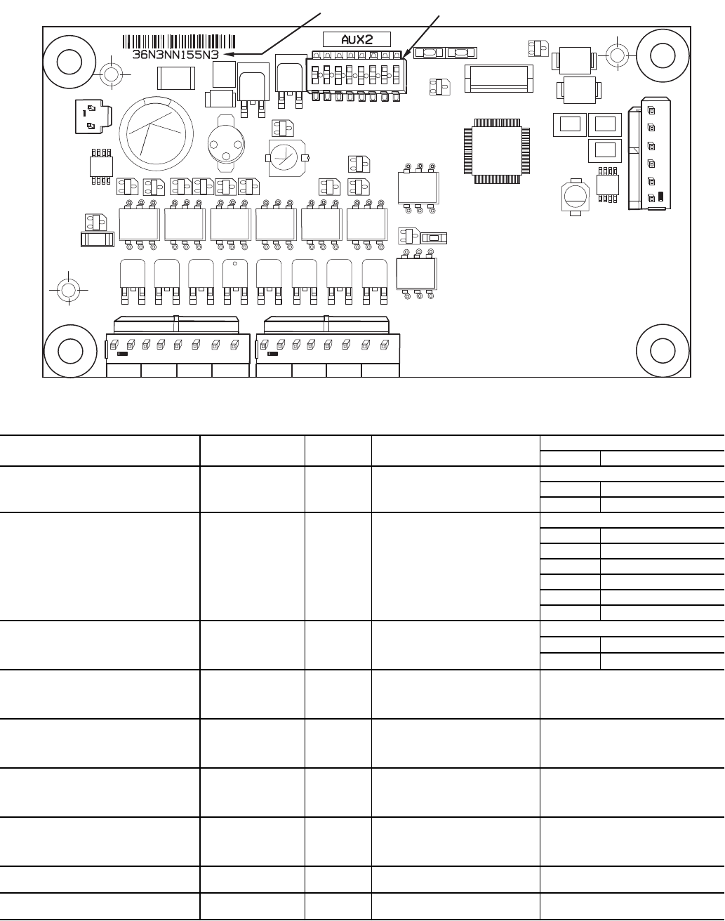
Main Base Board (MBB) — The MBB is the heart of
the ComfortLink control system, which contains the major
portion of operating software and controls the operation of the
machine. See Fig. 3. The MBB continuously monitors input/
output channel information received from its inputs and from
all other modules. The MBB receives inputs from status and
feedback switches, pressure transducers and thermistors. The
MBB also controls several outputs. Some inputs and outputs to
control the machine are located on other boards, but are trans-
mitted to or from the MBB via the internal communications
bus. Information is transmitted between modules via a 3-wire
communication bus or LEN (Local Equipment Network). The
CCN (Carrier Comfort Network
®
) bus is also supported. Con-
nections to both LEN and CCN buses are made at TB3. For a
complete description of main base board inputs and outputs
and their channel identifications, see Table 3.
221
221
221
221
195
195
195
195
195
195
195
CH1 CH2 CH3
CH4
CH11 CH12
LOCATION OF
SERIAL NUMBER
CH13
CH14
CH
15A
J4
ANALOG
INPUTS
J3
J2C
J2B
J15
J1A
J9D
+ G –
DISCRETE
INPUTS
J5A
C
16A
CH
15B
C
C
CH16B
11
C16
J2A
TR1 TR2 TR3 TR4 TR5
CH19 CH20 CH21 CH22 CH23 CH24 CH25 CH26
J8
CH17
CH18
J5B
J5C
THERMISTORS PRESSURES
CH5
CH6 CH7 CH8
CH9
J7A J7B
J7C
J7D
RELAY
OUTPUTS
MOV1
C41
C42 C43
C32
C33
C34
C35
12/11
12/11
J10
19 J12
J13
+ G -
S TATU S
J9A
K1
K2
D15
J6
CCN
CH10
+ G –
SIO
(LEN)
J9C
J9B
+ G –
Fig. 3 — Main Base Board

7
Table 3 — Main Base Board Inputs and Outputs
* Controls discharge and liquid line isolation solenoids for 30RB120-190 brine units only.
DESCRIPTION INPUT/OUTPUT I/O TYPE
SCROLLING MARQUEE
POINT NAME
CONNECTION POINT
Pin Notation
Power (24 vac supply) —— —
MBB-J1A, MBB-J1B
11 24 vac
12 Ground
Local Equipment Network —— —
MBB-J9A, MBB-J9B,
MBB-J9C, MBB-J9D
+
G
-
Carrier Comfort Network
®
(CCN)
—— —
MBB-J12
+
G
-
External Chilled
Water Pump Interlock
PMPI Switch INPUTSGEN.ILOCK MBB-J4-CH15A
Chilled Water Flow Switch CWFS Switch INPUTSGEN.ILOCK
MBB-J5A-CH15B
15B
Demand Limit Switch #1 Demand Limit SW1 Switch INPUTSGEN.IDLS1 MBB-J4-CH13
Circuit A Discharge
Pressure Transducer
DPTA
Pressure Transducer
(0-5 VDC)
PRESSUREPRC.ADP.A
MBB-J7A-CH6
5V 5 vdc Ref.
S Signal
R Return
Circuit B Discharge
Pressure Transducer
DPTB
Pressure Transducer
(0-5 VDC)
PRESSUREPRC.BDP.B
MBB-J7C-CH8
5V 5 vdc Ref.
S Signal
R Return
Dual Chiller
LWT Thermistor
DUAL 5k Thermistor TEMPERATUREUNITCHWS MBB-J6-CH3
Dual Set Point Input Dual Set Point Switch INPUTSGEN.IDUAL MBB-J4-CH12
Entering Water Thermistor EWT 5k Thermistor TEMPERATUREUNITEWT MBB-J6-CH2
Leaving Water Thermistor LWT 5k Thermistor TEMPERATUREUNITLWT MBB-J6-CH1
Outdoor Air Thermistor OAT 5k Thermistor TEMPERATUREUNITOAT MBB-J6-CH4
Pump #1 Interlock
Pump #2 Interlock
PMP1
PMP2
Switch INPUTSGEN.IPUMP
MBB-J5C-CH18
18
C
Reverse Rotation Board Reverse Rotation Board Switch INPUTSGEN.IELEC
MBB-J5A-CH16B
16B
Circuit A Suction
Pressure Transducer
SPTA
Pressure Transducer
(0-5 VDC)
PRESSUREPRC.ASP.A
MBB-J7B-CH7
5V 5 vdc Ref.
S Signal
R Return
Circuit B Suction
Pressure Transducer
SPTB
Pressure Transducer
(0-5 VDC)
PRESSUREPR.BSP.B
MBB-J7D-CH9
5V 5 vdc Ref.
S Signal
R Return
Unit Status Remote Contact-Off-Enable Switch INPUTSGEN.IONOF MBB-J4-CH11
Alarm Relay ALM R Relay OUTPUTSGEN.OALRM MBB-J3-CH24
Alert Relay ALT R Relay OUTPUTSGEN.OALRT MBB-J3-CH25
Cooler Heater CL-HT TRIAC OUTPUTSGEN.OCO.HT MBB-J2B-CH21
Circuit A Minimum
Load Control*
MLV-A TRIAC OUTPUTSCIR.AHGB.A MBB-J2C-CH22
Circuit B Minimum
Load Control*
MLV-B TRIAC OUTPUTSCIR.BHGB.B MBB-J2C-CH23
Pump #1 Starter
PMP1 TRIAC OUTPUTSGEN.OPMP.1 MBB-J2A-CH19
Pump #2 Starter PMP2 TRIAC OUTPUTSGEN.OPMP.2 MBB-J2A-CH20
Ready Relay RDY R Relay OUTPUTSGEN.OREDY MBB-J3-CH26

8
Scroll Protection Module (SPM) — There is one
SPM per compressor and it is responsible for controlling that
compressor. See Fig. 4. The device controls the compressor
contactor and the compressor crankcase heater. The SPM mod-
ule also monitors the compressor motor temperature, and cir-
cuit high pressure switch. The SPM responds to commands
from the MBB (main base board) and sends the MBB the
results of the channels it monitors via the LEN (Local
Equipment Network). See below for SPM board address infor-
mation. See Table 4 for SPM inputs and outputs.
SPM-A1 DIP
Switch
12345678
Address: ON OFF OFF OFF ON OFF OFF OFF
SPM-A2 DIP
Switch
123 456 7 8
Address: OFF ON OFF OFF ON OFF OFF OFF
SPM-A3 DIP
Switch
1 23456 7 8
Address: OFF OFF ON OFF ON OFF OFF OFF
SPM-A4 DIP
Switch
12345678
Address: OFF OFF OFF ON ON OFF OFF OFF
SPM-B1 DIP
Switch
12 3 4 567 8
Address: ON OFF OFF OFF OFF ON OFF OFF
SPM-B2 DIP
Switch
123 4 567 8
Address: OFF ON OFF OFF OFF ON OFF OFF
SPM-B3 DIP
Switch
1 234 567 8
Address: OFF OFF ON OFF OFF ON OFF OFF
SPM-B4 DIP
Switch
12345678
Address: OFF OFF OFF ON OFF ON OFF OFF
SPM-C1 DIP
Switch
12345678
Address: ON OFF OFF OFF OFF OFF ON OFF
SPM-C2 DIP
Switch
123 4 5 678
Address: OFF ON OFF OFF OFF OFF ON OFF
SPM-C3 DIP
Switch
1 234 5 678
Address: OFF OFF ON OFF OFF OFF ON OFF
SPM-C4 DIP
Switch
12345678
Address: OFF OFF OFF ON OFF OFF ON OFF
1
2
3
4
5
6
7
8
ON
103
103
LOCATION OF
SERIAL NUMBER
QC1
QC2
JP4
JP1
JP2
JP5
JP6
D4
C19
D6
D5
Q4
D7
Q5
D9
U3
Q6
D8 Q3
SMD
JP3
F1
C46
D13
D14
LED1
LED2
Fig. 4 — Scroll Protection Module

9
Electronic Expansion Valve (EXV) Board —
At least one EXV board is used in all machines. There is one
EXV board for 2-circuit machines. Three-circuit machines
have two EXV boards. See Fig. 5. The board is responsible for
monitoring the return gas temperature thermistors. The board
also signals the EXV motors to open or close. The electronic
expansion valve board responds to commands from the MBB
and sends the MBB the results of the channels it monitors via
the LEN (local equipment network). See below for DIP switch
information for EXV1 and EXV2. See Tables 5 and 6 for EXV
inputs and outputs.
Table 4 — Scroll Protection Module Inputs and Outputs*
* “x” denotes the circuit, A, B or C. “n” denotes the compressor number, 1, 2, 3, or 4.
Table 5 — EXV1 Board Inputs and Outputs
EXV1 DIP Switch 123456 7 8
Address: ON ON ON ON ON ON OFF ON
EXV2 DIP Switch 1 23456 7 8
Address: OFF ON ON ON ON ON OFF ON
DESCRIPTION INPUT/OUTPUT I/O TYPE
SCROLLING MARQUEE
POINT NAME
CONNECTION POINT
Pin Notation
Power (24 vac supply) —— —
SPM-xn-J1
QC1 24 vac
QC2 Ground
Local Equipment Network —— —
SPM-xn-JP1
1+
2G
3-
SPM-xn-JP2
2+
3G
4-
Circuit x High Pressure Switch HPS-x Switch Not available
SPM-xn-JP3
1
2
Compressor xn Motor Temperature MTR-xn PTC Thermistor Not available
SPM-xn-JP4
1
2
Compressor xn Contactor Cxn Relay OUTPUTSCIR.xCP.xn
SPM-xn-JP5
1
2
Crankcase Heater CCH Relay OUTPUTSCIR.xHT.xn
SPM-xn-JP6
1
2
Circuit x High Pressure Switch HPS-x Switch Not available
SPM-xn-JP2
1
DESCRIPTION INPUT/OUTPUT I/O TYPE
SCROLLING MARQUEE
POINT NAME
CONNECTION POINT
Pin Notation
Power (24 vac supply) —— —
EXV1-J1
11 24 vac
12 Ground
Local Equipment Network —— —
EXV1-J4
1+
2G
3–
Circuit A Suction Gas Thermistor SGTA 5k Thermistor TEMPERATURECIR.ASGT.A
EXV1-J3
THA
Circuit B Suction Gas Thermistor SGTB 5k Thermistor TEMPERATURECIR.BSGT.B
EXV1-J3
THB
Circuit A EXV EXV-A Stepper Motor OUTPUTSCIR.AEXV.A
EXV1-J2A
1
2
3
4
Circuit B EXV EXV-B Stepper Motor OUTPUTSCIR.BEXV.B
EXV1-J2B
1
2
3
4

10
Fan Boards — At least one fan board is installed in each
unit (see Fig. 6 and 7), except for 30RB080-190 units with the
high-efficiency variable condenser fan (HEVCF) option; fan
boards are not used with this option on these units. There are
two types of fan boards, with and without an analog output sig-
nal for the low ambient head pressure control fan speed con-
trollers. If a unit does not have low ambient head pressure con-
trol installed, it will not have the analog connection terminals.
The fan board responds to commands from the MBB and sends
the MBB the results of the channels it monitors via the LEN.
See below for fan board 1, 2 and 3 DIP switch addresses. See
Tables 7-9 for inputs and outputs.
1
2
3
4
5
6
7
8
ON
100
100
257-01
712
100K
100K
100
1
2
3
4
5
3
2
1
-
G
+
J3
1
2
3
4
5
J2A EXVA
J2B EXVB
24VAC
STATUS
MOV1
LOCATION OF
SERIAL NUMBER
4321
THA THB
D4
D6
J1
C15
C16
D5
U5
Q2 Q1
L4
U4
12/11
C17
+
Q45
Q42Q37
G2
Q35
Q25
Q27
Q30
Q20
Q22
Q17
Q15
Q12
Q10
C10
Q7
S1
C11
U2
D2
L1
U1
C37C39
SB
D15
U6
C25
C49
Q4
Q5
L2
R2
R3 L3
D1
R9
TEMP
D29
D9 D8
SI0
(LEN)
COMM J4
Fig. 5 — EXV Board
FAN BOARD 1
DIP Switch
123 45678
Address: OFF ON OFF OFF ON OFF ON OFF
FAN BOARD 2
DIP Switch
12345678
Address: ON ON OFF OFF ON OFF ON OFF
FAN BOARD 3
DIP Switch
1 2345678
Address: OFF OFF ON OFF ON OFF ON OFF

11
Table 6 — EXV2 Inputs and Outputs
NOTE: EXV2 inputs and outputs are only used on 30RB210-300.
DESCRIPTION INPUT/OUTPUT I/O TYPE
SCROLLING MARQUEE
POINT NAME
CONNECTION POINT
Pin Notation
Power (24 vac supply) —— —
EXV2-J1
11 24 vac
12 Ground
Local Equipment Network ——
—
EXV2-J4
1+
2G
3–
Circuit C Suction Gas Thermistor SGTC 5k Thermistor TEMPERATURECIR.CSGT.C
EXV2J3
THA
Circuit C EXV EXV-C Stepper Motor OUTPUTSCIR.CEXV.C
EXV2-J2A
1
2
3
4
1
2
3
4
5
6
7
8
ON
100K
100K
100K
CH1
CH2 CH3
CH4 CH5 CH6 CH7 CH8
TR1 TR2 TR3 TR4 TR5 TR6 TR7 TR8
STATUS SIO (LEN)
LOCATION OF
SERIAL NUMBER
24 VAC
CH13 CH14
J9
J1
CH9
CH10
CH11
CH12
JP2
C61
CH13
D12
JP1
L3
L5
U21
L2
D6
D5
Q5
Y1
D7
D8
S1
D3
U1
Q1
U5
U6
U7
U8
U9
Q10
Q11
U10
J4
J3
J2
U4
U2
Q12
Q60
3 2 1
– G +
3 2 1
– G +
DIP SWITCH
J5
J6
J7 J8
Fig. 6 — Fan Board (AUX 1) with Low Ambient Temperature Head Pressure Control

12
Table 7 — Fan Board 1 (AUX1, AUX2) Outputs*
*Fan boards 1 and 2 will use the AUX1 board when the low ambient temperature head pressure control option is installed.
†Supplied on AUX1 board only
NOTES:
1. Fan board 1 is used on 30RB060-390.
2. 24 vac TRIAC outputs may indicate 12-13 vac when output is
de-energized.
DESCRIPTION INPUT/OUTPUT I/O TYPE
SCROLLING MARQUEE
POINT NAME
CONNECTION POINT
Pin Notation
Power (24 vac supply) —— —
FB1-J1
11 24 vac
12 Ground
Local Equipment Network —— —
FB1-J9
+
G
-
+
G
-
Circuit A Low Ambient
Temperature Head Pressure
Control Speed Signal
MM-A† 0-10 VDC OUTPUTSCIR.ASPD.A
FB1-CH9
+
-
Circuit B Low Ambient Temperature
Head Pressure Control Speed Signal
(sizes 060-150, 210-250)
MM-B† 0-10 VDC OUTPUTSCIR.BSPD.B
FB1-CH10
+
-
Outdoor Fan Motor 1 OFM1
TRIAC
24 VAC
FB1-J2-CH1
(sizes 060-110)
FB1-J2-CH2
(sizes 120-150, 210-250)
FB1-J2-CH3
(sizes 160-190, 275, 300,
Duplex sizes 315-390)
Outdoor Fan Motor 2 OFM2
TRIAC
24 VAC
FB1-J2-CH2
(sizes 060-110)
FB1-J2-CH3
(sizes 120-150, 210-250)
FB1-J2-CH4
(sizes 160-190, 275, 300,
Duplex sizes 315-390)
Outdoor Fan Motor 3 OFM3
TRIAC
24 VAC
FB1-J2-CH3
(sizes 060,070,090-110)
FB1-J3-CH5
(size 080)
FB1-J2-CH1
(sizes 120-150, 210-250)
FB1-J2-CH2
(sizes 160-190, 275, 300,
Duplex sizes 315-390)
Outdoor Fan Motor 4 OFM4
TRIAC
24 VAC
FB1-J2-CH4
(sizes 060,070,130,
150,210-250)
FB1-J3-CH6
(size 080)
FB1-J3-CH7
(sizes 090-110)
FB1-J3-CH5
(sizes 160-190, 275-300,
Duplex sizes 315-390)
Outdoor Fan Motor 5 OFM5
TRIAC
24 VAC
FB1-J3-CH5
(sizes 090-110)
FB1-J3-CH6
(sizes 120-150, 210-250)
FB1-J2-CH1
(sizes 160-190, 275-300,
Duplex sizes 315-390)
Outdoor Fan Motor 6 OFM6
TRIAC
24 VAC
FB1-J3-CH6
(sizes 090-110,
160-190, 275-300,
Duplex sizes 315-390)
FB1-J3-CH7
(sizes 120-150, 210-250)
Outdoor Fan Motor 7 OFM7
TRIAC
24 VAC
FB1-J3-CH5
(sizes 120-150, 210-250)
Outdoor Fan Motor 8 OFM8
TRIAC
24 VAC
FB1-J3-CH8
(sizes 120-150, 210-250)
13
Table 8 — Fan Board 2 (AUX1, AUX2) Outputs*
*Fan boards 1 and 2 will use the AUX1 board when the low ambient temperature head pressure control option is installed.
†Output only on units with low ambient temperature head pressure control installed (AUX1).
NOTES:
1. Fan board 2 used on 30RB160-190, 275-300, 315-390.
2. 24 vac TRIAC outputs may indicate 12-13 vac when output is
de-energized.
DESCRIPTION INPUT/OUTPUT I/O TYPE
SCROLLING MARQUEE
POINT NAME
CONNECTION POINT
Pin Notation
Power (24 vac supply) —— —
FB2-J1
11 24 vac
12 Ground
Local Equipment Network —— —
FB2-J9
+
G
-
+
G
-
Circuit B Low Ambient Temperature
Head Pressure Control
Speed Signal
(sizes 160-190, 275-300, 315-400)
MM-B† 0-10 VDC OUTPUTSCIR.BSPD.B
FB2-CH9
+
-
Outdoor Fan Motor 7 OFM7†
TRIAC
24 VAC
FB2-J2-CH2
(sizes 160, 170, 315-345, 360B)
FB2-J2-CH3
(sizes 190, 275, 300, 360A, 390)
Outdoor Fan Motor 8 OFM8
TRIAC
24 VAC
FB2-J2-CH3
(sizes 160, 170, 315-345, 360B)
FB2-J2-CH4
(sizes 190, 275, 300, 360A, 390)
Outdoor Fan Motor 9 OFM9
TRIAC
24 VAC
FB2-J2-CH1
(sizes 160, 170, 315-345, 360B)
FB2-J2-CH2
(sizes 190, 275, 300, 360A, 390)
Outdoor Fan Motor 10 OFM10
TRIAC
24 VAC
FB2-J2-CH4
(sizes 160, 170, 315-345, 360B)
FB2-J3-CH5
(sizes 190, 275, 300, 360A, 390)
Outdoor Fan Motor 11 OFM11
TRIAC
24 VAC
FB2-J2-CH1
(sizes 190, 275-300, 360A, 390)
Outdoor Fan Motor 12 OFM12
TRIAC
24 VAC
FB2-J3-CH6
(sizes 190, 275-300, 360A, 390)
1
2
3
4
5
6
7
8
ON
100K
100K
100K
LOCATION OF
SERIAL NUMBER
TR1 TR2 TR3 TR4 TR5 TR6 TR7 TR8
CH1 CH2 CH3 CH4 CH5 CH6 CH7 CH8
STATUS SIO (LEN)
24 VAC
J1
J9
D4
U2
U5
Q2
Q7
Q3
U8
U9
Q9
Q10
Q11Q12
Q13
J4
J3
J2
S1
D7
Q5
Y1
D5
D6
L2
U6
U1
Q1
D3
C3
3 2 1
– G +
3 2 1
– G +
DIP SWITCH
Fig. 7 — Fan Board (AUX 2) without Low Ambient Temperature Head Pressure Control

14
Table 9 — Fan Board 3 (AUX1) Inputs and Outputs
*Controls discharge and liquid line isolation soleniods for 30RB210-300 brine units.
†Low ambient temperature head pressure control output is on AUX1 board only.
NOTES:
1. Fan board 3 used on 30RB210-300.
2. 24 vac TRIAC outputs may indicate 12-13 vac when output is
de-energized.
DESCRIPTION INPUT/OUTPUT I/O TYPE
SCROLLING MARQUEE
POINT NAME
CONNECTION POINT
(Unit Size)
Pin Notation
Power (24 vac supply) —— —
FB3-J1
11 24 vac
12 Ground
Local Equipment Network —— —
FB3-J9
+
G
-
+
G
-
Circuit C Discharge
Pressure Transducer
DPTC
Pressure Transducer
(0-5 VDC)
PRESSUREPRC.CDP.C FB3-J7-CH13
Circuit C Suction
Pressure Transducer
SPTC
Pressure Transducer
(0-5 VDC)
PRESSUREPRC.CSP.C FB3-J8-CH14
Minimum Load
Value Circuit C
MLV-C* TRIAC OUTPUTSCIR.CHGB.C
FB3-J3-CH7
(sizes 210-300)
Circuit C Low Ambient
Temperature Head Pressure
Control Speed Signal
(sizes 210-300)
MM-C† 0-10 VDC OUTPUTSCIR.CSPD.C
FB3-CH9
+
-
Outdoor Fan Motor 9 OFM9
TRIAC
24 VAC
FB3-J2-CH2
(sizes 210, 225)
FB3-J2-CH3
(size 250)
Outdoor Fan Motor 10 OFM10
TRIAC
24 VAC
FB3-J2-CH3
(sizes 210, 225)
FB3-J2-CH4
(size 250)
Outdoor Fan Motor 11 OFM11
TRIAC
24 VAC
FB3-J2-CH1
(sizes 210, 225)
FB3-J2-CH2
(size 250)
Outdoor Fan Motor 12 OFM12
TRIAC
24 VAC
FB3-J2-CH3
(sizes 210, 225)
FB3-J2-CH4
(size 250)
Outdoor Fan Motor 13 OFM13
TRIAC
24 VAC
FB3-J2-CH1
(size 250)
FB3-J2-CH2
(size 275)
FB3-J2-CH3
(size 300)
Outdoor Fan Motor 14 OFM14
TRIAC
24 VAC
FB3-J3-CH6
(size 250)
FB3-J2-CH3
(size 275)
FB3-J2-CH4
(size 300)
Outdoor Fan Motor 15 OFM15
TRIAC
24 VAC
FB3-J2-CH1
(size 275)
FB3-J2-CH2
(size 300)
Outdoor Fan Motor 16 OFM16
TRIAC
24 VAC
FB3-J2-CH4
(size 275)
FB3-J3-CH5
(size 300)
Outdoor Fan Motor 17 OFM17
TRIAC
24 VAC
FB3-J2-CH1
(size 300)
Outdoor Fan Motor 18 OFM18
TRIAC
24 VAC
FB3-J3-CH6
(size 300)

15
Reverse Rotation Board — The reverse rotation
board monitors the three-phase electrical system to provide
phase reversal, phase loss and under-voltage protection. See
Fig. 8. The reverse rotation board has two LEDs (light-emitting
diodes) and two adjustable dial settings. Under normal condi-
tions, the upper LED will light up green. The lower LED is red
and will flash (phase reversal) or turn on solid (phase loss and
under-voltage) according to the conditions sensed.
DIAL SETTINGS — The reverse rotation board has two di-
als. See Fig. 8. The upper dial should be set to match the in-
coming three-phase voltage to the chiller with no compressors
running. This dial must be adjusted for 208/230-v chillers oper-
ating on 208-v power supply. The dial should be adjusted to
200-v minimum setting for this case. The lower dial is used for
trip delay and should be set fully counterclockwise to the mini-
mum 0.1 second setting.
PHASE REVERSAL PROTECTION — The control moni-
tors the three-phase power sequence supplied at terminals L1,
L2, and L3. If the control senses an incorrect phase relation-
ship, the relay contacts (11/14) on the board will open. The re-
lay contacts will automatically reset when the correct phase se-
quence is applied.
PHASE LOSS AND UNDER-VOLTAGE PROTEC-
TION — If the reverse rotation board senses that any one of
the three phase inputs has no AC voltage or that any one phase
has dropped more than 20% below the voltage dial setting, the
relay contacts (11/14) on the board will open. Contacts will re-
set automatically when all three phases are present, in the cor-
rect sequence and are within the limits of the voltage dial
setting.
NOTE: Normal operation of the reverse rotation board (for
example, no faults are detected) results in a closed contact
being applied to the MBB (plug J5A, channel 16B) through the
closed 11/14 relay contact.
Enable-Off-Remote Contact Switch — This switch
is installed in all units and provides the owner and service
person with a local means of enabling or disabling the
machine. It is a 3-position switch used to control the chiller.
When switched to the Enable position the chiller is under its
own control. Move the switch to the Off position to shut the
chiller down. Move the switch to the Remote Contact position
and a field-installed dry contact can be used to start the chiller.
The contacts must be capable of handling a 24-vac, 20-mA
load. In the Enable and Remote Contact (dry contacts closed)
positions, the chiller is allowed to operate and respond to the
scheduling configuration, CCN configuration and set point
control.
Emergency On/Off Switch — This switch is installed
in all units. The Emergency On/Off switch should only be used
when it is required to shut the chiller off immediately. Power
to the MBB, energy management module, and scrolling
marquee display is interrupted when this switch is off and all
outputs from these modules will be turned off.
Energy Management Module (EMM) — The EMM
is available as a factory-installed option or as a field-installed
accessory. The EMM receives 4 to 20 mA inputs for the
temperature reset, cooling set point reset and demand limit
functions. The EMM also receives the switch inputs for the
field-installed second stage 2-step or 3-step demand limit, ice
done, occupancy overrides, and remote lockout functions. The
EMM communicates the status of all inputs with the MBB, and
the MBB adjusts the control point, capacity limit, and other
functions according to the inputs received. The EMM gener-
ates a 0 to 10 vdc output that directly corresponds to the unit
percent total capacity. Contacts indicating unit run status and
shutdown status are provided. See Table 10 and Fig. 9.
LED STATUS FUNCTION
Upper (green) LED on
continuously
Relay contacts closed (normal
operation)
Lower (red) LED blinking Relay contacts open (phase rever-
sal has occurred)
Lower (red) LED on
continuously
Relay contacts open (phase loss
or under-voltage has occurred)
Upper (green) LED off Power not present at L1, L2, L3
(off)
CAUTION
Care should be taken when interfacing with other manufac-
turer’s control systems due to possible power supply differ-
ences, full wave bridge versus half wave rectification,
which could lead to equipment damage. The two different
power supplies cannot be mixed. ComfortLink controls use
half wave rectification. A signal isolation device should be
utilized if incorporating a full wave bridge rectifier signal
generating device is used.
Fig. 8 — Reverse Rotation Board (RRB)

16
Energy Management Module Heat Reclaim
(EMM HR) — The EMM HR is available as a factory-in-
stalled option. The EMM HR communicates the status of all of
the inputs with the MBB. The MBB then determines the
appropriate operating mode. Operating modes are: normal
cooling, heat reclaim, and simultaneous one circuit cooling/one
circuit heat reclaim. See Table 11 and Fig. 9.
Table 10 — Energy Management Module (EMM) Inputs and Outputs
* 250 ohm, 1/2 watt resistor required for 4-20 mA input.
INPUT DESCRIPTION I/O TYPE I/O POINT NAME CONNECTION POINT
4-20 mA or 0-5 vdc Demand Limit 4-20 mA Demand Limit 0-5 vdc* INPUTSGEN.IDMND EMM-J7B-CH6
4-20 mA or 0-5 vdc Temperature Reset/Setpoint
4-20 mA Temperature Reset/
Set point
0-5 vdc* INPUTSGEN.IRSET EMM-J7A-CH5
Demand Limit SW2 Demand Limit Step 2 Switch Input INPUTSGEN.IDLS2 EMM-J4-CH9
Ice Done Ice Done Switch Switch Input INPUTSGEN.IICE.D EMM-J4-CH11A
Occupancy Override Occupied Schedule Override Switch Input INPUTSGEN.IOCCS EMM-J4-CH8
Remote Lockout Switch Chiller Lockout Switch Input INPUTSGEN.IRLOC EMM-J4-CH10
SPT
Space Temperature
Thermistor
10k Thermistor TEMPERATUREUNITSPT EMM-J6-CH2
OUTPUT DESCRIPTION I/O TYPE I/O POINT NAME CONNECTION POINT
% Total Capacity 0-10 vdc OUTPUTSGEN.OCATO EMM-J8-CH7
RUN R Run Relay Relay OUTPUTSGEN.ORUN EMM-J3-CH24
SHD R Shutdown Relay Relay OUTPUTSGEN.OSHUT EMM-J3-CH25
221
221
221
221
100K
100K
100K
100K
100K
CH
17
CH
17
CH
16
CH
CH
18
CH
19
CH
20
CH
22
CH
21
CH
23
24 VAC
12 11
CH
11b
CH
12
CH
13
CH
14
CH
15
CH
1
CH
2
CH
3
CH
4
CH 5
CH 6
CH 7
SIO LEN
+ G -
+ G -
SIO LEN
J8
J7B
J7A
J6
J5
J4 J3 J2B
J2A
J1
Fig. 9 — Energy Management Module and Energy Management Heat Reclaim Module
a30-4465

17
Table 11 — Energy Management Module Heat Reclaim (EMM HR) Inputs and Outputs
Local Equipment Network — Information is trans-
mitted between modules via a 3-wire communication bus or
LEN (Local Equipment Network). External connection to the
LEN bus is made at TB3.
Board Addresses — All boards (except the main base
board and the energy management module) have 8-position
DIP switches. Addresses for all boards are listed with the input/
output tables for each board.
Control Module Communication
RED LED — Proper operation of the control boards can be
visually checked by looking at the red status LEDs (light-
emitting diodes). When operating correctly, the red status
LEDs will blink in unison at a rate of once every 2 seconds. If
the red LEDs are not blinking in unison, verify that correct
power is being supplied to all modules. Be sure that the main
base board (MBB) is supplied with the current software. If nec-
essary, reload current software. If the problem still persists, re-
place the MBB. A red LED that is lit continuously or blinking
at a rate of once per second or faster indicates that the board
should be replaced.
GREEN LED — All boards have a green LEN (Local Equip-
ment Network) (SIO) LED which should be blinking whenever
power is on. If the LEDs are not blinking as described check
LEN connections for potential communication errors at the
board connectors. See Table 3 for LEN connector designations.
A 3-wire bus accomplishes communication between modules.
These 3 wires run in parallel from module to module. The J9A
connector on the MBB provides communication directly to the
scrolling marquee display or the Navigator™ display module.
YELLOW LED — The MBB has one yellow LED. The
Carrier Comfort Network
®
(CCN) LED will blink during times
of network communication.
Carrier Comfort Network (CCN) Interface — All
30RB units can be connected to the CCN, if desired. The com-
munication bus wiring is a shielded, 3-conductor cable with
drain wire and is field supplied and installed. The system ele-
ments are connected to the communication bus in a daisy chain
arrangement. The positive pin of each system element commu-
nication connector must be wired to the positive pins of the
system elements on either side of it, that is also required for the
negative and signal ground pins of each system element. Wir-
ing connections for CCN should be made at TB3. Consult the
CCN Contractor’s Manual for further information. See Fig. 10.
NOTE: Conductors and drain wire must be 20 AWG (Ameri-
can Wire Gage) minimum stranded, tinned copper. Individual
conductors must be insulated with PVC, PVC/nylon, vinyl,
Teflon*, or polyethylene. An aluminum/polyester 100% foil
shield and an outer jacket of PVC, PVC/nylon, chrome vinyl,
or Teflon with a minimum operating temperature range of
–20 C to 60 C is required. See Table 12 for recommended wire
manufacturers and part numbers.
INPUT DESCRIPTION I/O TYPE I/O POINT NAME CONNECTION POINT
PD.B Circuit B Pumpdown Pressure Transducer Pressure Transducer PRESSURECIR.BPD.B EMM-J8-CH6
PD.A Circuit A Pumpdown Pressure Transducer Pressure Transducer PRESSURECIR.APD.A EMM-J8-CH5
HRS.B Circuit B Liquid Subcooling — TEMPERATURECIR.BHRS.B —
HRS.A Circuit A Liquid Subcooling — TEMPERATURECIR.AHRS.A —
HRT.B Circuit B Liquid Temperature Temperature TEMPERATURE CIR.BHRT.B EMM-J5-CH4
HRT.A Circuit A Liquid Temperature Temperature TEMPERATURE CIR.AHRT.A EMM-J5-CH3
HEWT Heat Reclaim Entering Fluid Temperature TEMPERATUREUNITHEWT EMM-J5-CH2
HLWT Heat Reclaim Leaving Fluid Temperature TEMPERATUREUNITHLWT EMM-J5-CH1
C.FLO Condenser Flow Switch Status Switch INPUTSGEN.IC.FLO EMM-J5-CH15
— Power (24 vac supply) — — EMM-J1-CH11,12
— Local Equipment Network — — EMM-J9
OUTPUT DESCRIPTION I/O TYPE I/O POINT NAME CONNECTION POINT
Condenser 0-10 VDC Water Valve Output 0-10 VDC — EMM-J8-CH7
CND.P Heat Reclaim Condenser Pump Status Contactor OUTPUTSGEN.OCND.P EMM-J2-CH16
CN.HT Heat Reclaim Condenser Heater Contactor OUTPUTSGEN.OCN.HT EMM-J2-CH17
HR2.A Circuit A, Leaving Air-Cooled Cond Solenoid Contactor OUTPUTSCIR.AHR2.A EMM-J2-CH18
HR2.B Circuit B, Leaving Air-Cooled Cond Solenoid Contactor OUTPUTSCIR.BHR2.B EMM-J2-CH19
HR3.A Circuit A, Entering Water-Cooled Cond Solenoid Contactor OUTPUTSCIR.AHR3.A EMM-J2-CH20
HR3.B Circuit B, Entering Water-Cooled Cond Solenoid Contactor OUTPUTSCIR.BHR3.B EMM-J2-CH21
HR4.A Circuit A, Leaving Water-Cooled Cond Solenoid Contactor OUTPUTSCIR.AHR4.A EMM-J2-CH22
HR4.B Circuit B, Leaving Water-Cooled Cond Solenoid Contactor OUTPUTSCIR.BHR4.B EMM-J2-CH23
HR1.A Circuit A, Entering Air-Cooled Cond Solenoid Contactor OUTPUTSCIR.AHR1.A EMM-J3-CH24
HR1.B Circuit B, Entering Air-Cooled Cond Solenoid Contactor OUTPUTSCIR.BHR1.B EMM-J3-CH25
Fig. 10 — ComfortLink CCN Communication Wiring
*Registered trademark of DuPont.

18
Table 12 — CCN Communication Bus Wiring
When connecting to a CCN communication bus, use a col-
or-coding scheme for the entire network to simplify the instal-
lation. It is recommended that red be used for the signal posi-
tive, black for the signal negative, and white for the signal
ground. Use a similar scheme for cables containing different
colored wires.
At each system element, tie the shields of its communica-
tion bus cables together. If the communication bus is entirely
within one building, the resulting continuous shield must be
connected to a ground at one point only. If the communication
bus cable exits from one building and enters another, the
shields must be connected to grounds at the lightning suppres-
sor in each building where the cable enters or exits the building
(one point per building only). To connect the unit to the net-
work:
1. Turn off power to the control box.
2. Cut the CCN wire and strip the ends of the red (+), white
(ground), and black (–) conductors. (Substitute appropri-
ate colors for different colored cables.)
3. Connect the red wire to (+) terminal on TB3 of the plug,
the white wire to COM terminal, and the black wire to the
(–) terminal.
4. The RJ14 CCN connector on TB3 can also be used, but is
only intended for temporary connection (for example, a
laptop computer running Service Tool).
Configuration Options — The unit Remote-OFF-En-
able switch must be in the OFF position while making changes.
If the unit switch is not in the OFF position, REJECTED may
be displayed on the scrolling marquee display.
MINIMUM LOAD CONTROL (ConfigurationUNIT
HGBP) reduces the capacity of the 30RB chiller below the
lowest standard capacity step by use of hot gas bypass. This
capacity step reduction provides more precise control of the
leaving water temperature. The minimum load valve acces-
sory cannot be used on units configured for brine as the
cooler fluid type (Configuration→ SERV→FLUD). Refer
to Brine Chiller Operation for additional information.
Minimum Load Control can be configured in three different
ways. If Minimum Load Control is not used, HGBP must be
set to 0. If HGBP is set to 1, the control will activate the mini-
mum load control valve when the machine is started only. This
will be the first step of capacity. If HGBP is set to 2, all stages
of capacity can utilize the minimum load control valve. If
HGBP is set to 3, the minimum load control valve will be used
only when the circuit has a high pressure override active. This
will reduce the capacity of the circuit.
RAMP LOADING (ConfigurationOPTNRL.S) limits
the rate of change of leaving fluid temperature. If the unit is in
a Cooling mode and configured for Ramp Loading, the control
makes 2 comparisons before deciding to change stages of
capacity. The control calculates a temperature difference
between the control point and leaving fluid temperature. If the
difference is greater than 4° F (2.2° C) and the rate of change
(°F or °C per minute) is more than the configured Cool Ramp
Loading (SetpointsCOOLCRMP), the control does not
allow any changes to the current stage of capacity.
MINUTES OFF TIME (ConfigurationOPTNDELY) is
a time delay added to the start when the machine is com-
manded ON. This is a field configurable item from 1 to
15 minutes. The factory default is 1 minute. This feature is
useful when multiple units are installed. Staggering the start
will reduce the inrush potential.
Dual Chiller Control — The dual chiller routine is
available for the control of two parallel units supplying chilled
fluid on a common loop. This control is designed for a parallel
fluid flow arrangement only. One chiller must be configured as
the master chiller, the other as the slave chiller. An additional
leaving fluid temperature thermistor (dual chiller LWT) must
be installed in the common chilled water piping as described in
the Installation Instructions for both the master and slave
chillers. See the Field Wiring section in the 30RB Installation
Instructions for dual chiller LWT sensor control wiring. A
chilled water flow switch is factory-installed for each chiller.
Parallel chiller control with dedicated pumps is recom-
mended. Chiller must start and stop its own water pump locat-
ed on its own piping. If pumps are not dedicated for each
chiller, chiller isolation valves are required: each chiller must
open and close its own isolation valve through the control
(valve shall be connected to the pump outputs). Pump Control
is enabled as described in the Cooler Pump Control section on
page 29. One additional parameter is set for the dual chiller
control. Lag Unit Pump Select (ConfigurationRSET
LAGP) allows the user to configure the control to energize
the pump for the lag chiller once the unit enters an occupied
time period or delay the control until the lag chiller is started. It
is recommended that this parameter be set to 0, OFF IF UNIT
STOPPED. The control of the slave chiller is directed through
commands emitted by the master chiller. The slave chiller has
no action in master/slave operations; it shall only verify that
CCN communication with its master is present. See the Dual
Chiller Sequence of Operation section on page 45.
Use dual chiller control to designate a lead chiller between
the master and slave chiller. Configure the Lead/Lag Balance
Select (ConfigurationRSETLLBL) to ENBL to base the
selection on the Lead/Lag Balance Delta (Configuration
RSETLLBD) between the master and slave run hours. If
the run hour difference between the master and the slave
remains less than LLBD, the chiller designated as the lead will
remain the lead chiller. The Lead/Lag changeover between the
master and the slave chiller due to hour balance will occur dur-
ing chiller operating odd days, such as day 1, day 3, and day 5
of the month, at 12:00 a.m. If a lead chiller is not designated,
the master chiller will always be designated the lead chiller.
The dual chiller control algorithm has the ability to delay
the start of the lag chiller in two ways. The Lead Pulldown
Time (ConfigurationRSETLPUL) provides a field con-
figurable time delay of 0 to 60 minutes. This time delay gives
the lead chiller a chance to remove the heat that the chilled wa-
ter loop picked up while being inactive during an unoccupied
period. The Lead Pulldown Time parameter is a one-time time
delay initiated after starting the lead chiller, manually or by a
schedule, before checking whether to start an additional chiller.
This routine provides the lead chiller an opportunity to pull
down the loop temperature before starting another chiller. The
second time delay, Lead/Lag Delay (Configuration
RSETLLDY) is a time delay imposed between the last
stage of the lead chiller and the start of the lag chiller. This pre-
vents enabling the lag chiller until the lead/lag delay timer has
expired. See Tables 13 and 14.
MANUFACTURER
PART NUMBER
Regular Wiring Plenum Wiring
Alpha 1895 —
American A21451 A48301
Belden 8205 884421
Columbia D6451 —
Manhattan M13402 M64430
Quabik 6130 —
IMPORTANT: A shorted CCN bus cable will prevent
some routines from running and may prevent the unit
from starting. If abnormal conditions occur, discon-
nect the CCN bus. If conditions return to normal,
check the CCN connector and cable. Run new cable if
necessary. A short in one section of the bus can cause
problems with all system elements on the bus.
19
Table 13 — Configuring the Master Chiller
NOTE: Bold values indicate sub-mode level.
MODE KEYPAD ENTRY DISPLAY ITEM EXPANSION COMMENT
CONFIGURATION
DISP
UNIT
SERV
OPTN
CCNA CCN Address
Confirm address of chiller. The master and slave chiller
must have different addresses.
1 Factory default address is 1.
CCNA
CCNB CCN Bus Number
Confirm the bus number of the chiller. The master and slave
chiller must be on the same bus.
0 Factory default is 0.
CCNB
OPTN
RSET
Reset Cool and Heat Tmp
CRST Cooling Reset Type
x5
MSSL Master/Slave Select
0 Disable
0 Disable Flashing to indicate Edit mode. May require Password.
1 Master Use up arrows to change value to 1.
1 Accepts the change.
MSSL
SLVA Slave Address
1
1 Flashing to indicate Edit mode.
2
Use up arrows to change value to 2. This address must
match the address of the slave chiller.
2 Accepts the change.
SLVA
LLBL Lead/Lag Balance Select
ENBL Factory Default is ENBL
LLBL
LLBD Lead/Lag Balance Delta
168 Factory Default is 168.
LLBD
LLDY Lead/Lag Start Delay
10 Factory Default is 10.
LLDY
LAGP Lag Unit Pump Select
0 Off if U Stp
Factory Default is 0, Off if unit is stopped. Master and slave
chiller must be configured to the same value.
LAGP
LPUL Lead Pulldown Time
0 Factory Default is 0.
At mode level.
OPERATING
MODES
SLCT
OPER
Operating Control Type
0 Switch Control
Master chiller should be configured for job requirements,
Switch Control, Time Schedule, or CCN.
At mode level.
ENTER
ENTER
ENTER
ESCAPE
ENTER
ESCAPE
ESCAPE
ENTER
ENTER
ENTER
ENTER
ESCAPE
ENTER
ENTER
ENTER
ESCAPE
ENTER
ESCAPE
ENTER
ESCAPE
ENTER
ESCAPE
ENTER
ESCAPE
ENTER
ESCAPE
ESCAPE
ENTER
ENTER
ENTER
ESCAPE
20
Table 14 — Configuring the Slave Chiller
NOTE: Bold values indicate sub-mode level.
MODE KEYPAD ENTRY DISPLAY ITEM EXPANSION COMMENT
CONFIGURATION
DISP
UNIT
SERV
OPTN
CCNA CCN Address Confirm address of chiller. The master and slave chiller
must have different addresses.
1 Factory default address is 1. The slave chiller address
must match what was programmed in the Master Chiller
SLVA item.
1 Flashing to indicate Edit Mode.
2 This item must match Master Chiller SLVA item.
2 Accepts the change.
CCNA
CCNB CCN Bus Number Confirm the bus number of the chiller. The master and
slave chiller must be on the same bus.
0 Factory default bus number is 0.
CCNB
OPTN
RSET Reset Cool and Heat Tmp
CRST Cooling Reset Type
x 5 MSSL Master/Slave Select
0 Disable
0 Disable Flashing to indicate Edit mode. May require Password
2 Slave Use up arrows to change value to 2.
2 Accepts the change.
MSSL
SLVA Slave Address Not required.
LLBL Lead/Lag Balance Select Not required.
LLBD Lead/Lag Balance Delta Not required.
LLDY Lead/Lag Start Delay Not required.
LAGP Lag Unit Pump Select Must be configured to the same value as the master
chiller.
LPUL Lead Pulldown Time Not required.
At mode level
OPERATING MODES
SLCT
OPER Operating Control Type
0 Switch Control
0 Flashing to indicate Edit Mode.
2 CCN Control Use up arrows to change value to 2.
NOTE: Slave chiller must be configured for CCN.
2 Accepts the value.
OPER
At mode level
ENTER
ENTER
ENTER
ENTER
ENTER
ESCAPE
ENTER
ESCAPE
ESCAPE
ENTER
ENTER
ENTER
ENTER
ESCAPE
ESCAPE
ESCAPE
ENTER
ENTER
ENTER
ENTER
ENTER
ESCAPE
ESCAPE

21
The Lag Unit Pump Select configuration must be set
consistently. If pump control is NOT being used, set Con-
figurationRSETLAGP to 1. If pump control IS being
used, set ConfigurationRSETLAGP to 0, which is the
default value. This must be set in both the master and slave
chillers, and it must be consistent in both.
Capacity Control — The control system cycles com-
pressors and minimum load valve solenoids (if equipped) to
maintain the user-configured leaving chilled fluid temperature
set point. Entering fluid temperature is used by the main base
board (MBB) to determine the temperature drop across the
cooler and is used in determining the optimum time to add or
subtract capacity stages. Entering fluid temperature, space
temperature (requires additional sensor), or outdoor-air temper-
ature reset features can automatically reset the leaving chilled
fluid temperature set point. It can also be reset from an external
4 to 20-mA signal (requires energy management module).
The control has an automatic lead-lag feature built in for
circuit and compressor starts. If enabled, the control will deter-
mine which circuit (ConfigurationOPTNLLCS=0) and
compressor to start to even the wear. The compressor wear
factor (combination of starts and run hours) is used to deter-
mine which compressor starts.
Compressor Wear Factor = (Compressor Starts) + 0.1
(Compressor Run Hours)
In this case, the circuit with the lowest average compressor
wear factor (the average of the wear factors of all available
compressors in the circuit) is the circuit that starts first. The
compressor within the circuit with the lowest wear factor is the
first to start. If the automatic lead-lag function for the circuit is
not enabled [ConfigurationOPTNLLCS=1 (Circuit A
leads), 2 (Circuit B leads), or 3 (Circuit C leads)], then the se-
lected circuit will be the first to start. Again, the compressor
with the lowest wear factor within the circuit will be the first to
start. If Minimum Load Control is enabled (Configuration
UNITHGBP=1), the valve will be operational only during
the first stage of cooling.
Once the lead compressor has been started, the lag compres-
sors will be determined by the wear factor and loading
sequence selected. If equal loading is selected, (Configura-
tionOPTNLOAD=0), the circuit with the lowest average
wear factor for the available compressors will start next, with
the compressor with the lowest wear factor starting. The con-
trol will attempt to keep all circuits at approximately the same
number of compressors ON. For this option to function proper-
ly, all circuits must have the same number of compressors
available. If a circuit compressor is not available due to an
alarm condition or demand limit, the capacity staging will
change to staged. If staged loading is selected, (Configura-
tionOPTNLOAD=1), the started circuit will continue to
turn on compressors according to the lowest wear factor until
all are on, then start the next circuit with the lowest average
wear factor. If Minimum Load Control is enabled for close
control (ConfigurationUNITHGBP=2), the valve will be
available at all stages for better temperature control. If
Minimum Load Control is enabled for high ambient control
(ConfigurationUNITHGBP=3), the valve will be used
only when a high pressure override is active for that circuit.
The electronic expansion valves provide a controlled start-
up. During start-up, the low pressure logic in the lead circuit
will be ignored for 5 minutes to allow for the transient changes
during start-up. As additional stages of compression are
required, the processor control will add them. The following
example is based on a 30RB225 machine, which has three
25-ton compressors in each circuit. See Table 15.
Each example below has different configurations and is
intended to illustrate the loading sequences possible for normal
operation.
In Example 1 (Table 16), assume the following configurations
are in place:
ConfigurationUNITHGBP=1. . Minimum Load Control
installed and enabled for Start-Up Only
ConfigurationOPTNLOAD=0 . . .Equal Circuit Loading
ConfigurationOPTNLLCS=0 . .Automatic Circuit Select
Since Circuit A has the lowest average wear factor, it will be
the lead circuit. Within the circuit, compressor A3 has the
lowest wear factor and will start first with Minimum Load
Control ON. The next stage will turn OFF the minimum load
control. Stage 3 will start another circuit because of the Equal
Circuit Loading configuration. The next circuit with the lowest
wear factor is Circuit B, and the compressor with the lowest
wear factor is B2. The next stage will be a circuit C compres-
sor. The process continues until all compressors are ON. See
Table 16.
In Example 2 (Table 17), assume the compressor starts and
run hours are the same as in the previous example and the
following configurations are in place:
ConfigurationUNITHGBP=1. . Minimum Load Control
installed and enabled for Start-Up Only
ConfigurationOPTNLOAD=1 . . Staged Circuit Loading
ConfigurationOPTNLLCS=0 . .Automatic Circuit Select
Since Circuit A has the lowest average wear factor, it will be
the lead circuit. Within the circuit, compressor A3 has the
lowest wear factor and will start first with Minimum Load
Control ON. The next stage will turn OFF the minimum load
control. Stage 3 will start a compressor in the same circuit be-
cause of the Staged Circuit Loading configuration. Compressor
A2 has the next lowest wear factor and will be started next.
Compressor A3 will be next to start. Since all compressors in
Circuit A are ON, the next stage will start another circuit. Of
the remaining circuits, Circuit B has the lowest wear factor, and
the compressor with the lowest wear factor is B2. All of the
Circuit B compressors will be started in the same manner as
Circuit A. Once all Circuit B compressors are ON, then Circuit
C will be started. The process continues until all compressors
are ON. See Table 17.
Table 15 — Compressor Starts and Run Hours
COMPRESSOR STARTS RUN HOURS WEAR FACTOR
CIRCUIT AVERAGE
WEAR FACTOR
A1 25 249 49.9
44.8A2 22 237 45.7
A3 26 128 38.8
B1 41 453 86.3
67.6B2 38 138 51.8
B3 35 297 64.7
C1 93 103 103.3
80.3C2 57 98 66.8
C3 61 99 70.9

22
Table 16 — Compressor Stages and Circuit Cycling, Example 1
LEGEND NOTES:
1. Total Cap. (Total Unit Capacity) and Cir. Cap. (Circuit Capacity)
are approximate percentage values.
2. Example is to determine minimum load control, staged circuit
loading, and automatic circuit select.
Table 17 — Compressor Stage and Circuit Cycling, Example 2
LEGEND NOTES:
1. Total Cap. (Total Unit Capacity) and Cir. Cap. (Circuit Capacity)
are approximate percentage values.
2. Example is to determine minimum load control, staged circuit
loading, and automatic circuit select.
In Example 3 (Table 18), assume the following configurations
are in place:
ConfigurationUNITHGBP=1 . . Minimum Load Control
installed and enabled for Start-Up Only
ConfigurationOPTNLOAD=0. . . Equal Circuit Loading
ConfigurationOPTNLLCS=2 . . . . . . . . . Circuit B Leads
Since Circuit B has been selected, it will be the lead circuit.
Within the circuit, compressor B2 has the lowest wear factor
and will start first with Minimum Load Control ON. The next
stage will turn OFF the minimum load control. Stage 3 will
start another circuit because of the Equal Circuit Loading
configuration. Comparing Circuit A and C, the circuit with the
lowest average wear factor is Circuit A, and the compressor
with the lowest wear factor is A3. The next stage will be a
circuit C compressor. The process continues until all compres-
sors are ON. See Table 18.
In Example 4 (Table 19), assume the compressor starts and
run hours are the same as in the first example and the following
configurations are in place:
ConfigurationUNITHGBP=1 . . Minimum Load Control
installed and enabled for Start-Up Only
ConfigurationOPTNLOAD=1. . .Staged Circuit Loading
ConfigurationOPTNLLCS=3 . . . . . . . . . Circuit C Leads
Since Circuit C has been selected, it will be the lead circuit.
Within the circuit, compressor C2 has the lowest wear factor
and will start first with Minimum Load Control ON. The next
stage will turn OFF the minimum load control. Stage 3 will
start a compressor in the same circuit because of the Staged
Circuit Loading configuration. Compressor C3 has the next
lowest wear factor and will be started next. Compressor C1
will be next to start. Since all compressors in Circuit C are ON,
the next stage will start another circuit. Of the remaining
circuits, Circuit A has the lowest wear factor, and the compres-
sor with the lowest wear factor is A3. All of the Circuit A com-
pressors will be started in the same manner as Circuit C. Once
all Circuit A compressors are ON, then Circuit B will be start-
ed. The process continues until all compressors are ON. See
Table 19.
If the circuit capacity is to be reduced, the compressor with
the highest wear factor will be shut off first (in most cases).
With Equal Circuit Loading, stages will be removed from each
circuit, following the same criteria used in the loading
sequence, but in the opposite order. Shown in Table 19 based
on the current wear factor in the opposite to the loading
sequence shown above, the compressor with the highest wear
factor will be removed first. When Staged Circuit Loading is
selected, the capacity from the last lag circuit will be removed
first.
STAGE
TOTAL
CAP.
CIRCUIT A CIRCUIT B CIRCUIT C
Cir.
Cap.
MLC A1 A2 A3
Cir.
Cap.
MLC B1 B2 B3
Cir.
Cap.
MLC C1 C2 C3
0 00 0 0
1 824X X0 0
2 11 33 X 0 0
3 22 33 X 33 X 0
4 33 33 X 33 X 33 X
5 44 66 X X 33 X 33 X
6 55 66 X X 66 X X 33 X
7 66 66 X X 66 X X 66 X X
8 77 100 X X X 66 X X 66 X X
9 88 100 X X X 100 X X X 66 X X
10 100 100 X X X 100 X X X 100 X X X
MLC — Minimum Load Control
STAGE
TOTAL
CAP.
CIRCUIT A CIRCUIT B CIRCUIT C
Cir.
Cap.
MLC A1 A2 A3
Cir.
Cap.
MLC B1 B2 B3
Cir.
Cap.
MLC C1 C2 C3
0 00 0 0
1 824X X 0 0
2 11 33 X 0 0
3 22 66 X X 0 0
4 33 100 X X X 0 0
5 44 100 X X X 33 X 0
6 55 100 X X X 66 X X 0
7 66 100 X X X 100 X X X 0
8 77 100 X X X 100 X X X 33 X
9 88 100 X X X 100 X X X 66 X X
10 100 100 X X X 100 X X X 100 X X X
MLC — Minimum Load Control

23
Table 18 — Compressor Stage and Circuit Cycling, Example 3
LEGEND NOTES:
1. Total Cap. (Total Unit Capacity) and Cir. Cap. (Circuit Capacity)
are approximate percentage values.
2. Example is to determine minimum load control, staged circuit
loading, and automatic circuit select.
Table 19 — Compressor Stage and Circuit Cycling, Example 4
LEGEND NOTES:
1. Total Cap. (Total Unit Capacity) and Cir. Cap. (Circuit Capacity)
are approximate percentage values.
2. Example is to determine minimum load control, staged circuit
loading, and automatic circuit select.
The capacity control algorithm runs every 30 seconds. The
algorithm attempts to maintain the Control Point at the desired
set point. Each time it runs, the control reads the entering and
leaving fluid temperatures. The control determines the rate at
which conditions are changing and calculates 2 variables based
on these conditions. Next, a capacity ratio (SM2) is calculated
using the 2 variables to determine whether or not to make any
changes to the current stages of capacity. This ratio value
ranges from –100 to +100%. If the next stage of capacity is a
compressor, the control starts (stops) a compressor when the
ratio reaches +100% (–100%). If the next stage of capacity
is the Minimum Load Control, the control energizes (deener-
gizes) the Minimum Load Control when the ratio reaches
+60% (–60%). If installed, the minimum load valve solenoid
will be energized with the first stage of capacity. The control
will also use the minimum load valve solenoid as the last stage
of capacity before turning off the last compressor. If the close
control feature (ConfigurationUNITHGBP=2) is en-
abled the control will use the minimum load valve solenoid
whenever possible to fine tune leaving fluid temperature con-
trol. A delay of 90 seconds occurs after each capacity step
change with Minimum Load Control. A delay of 3 minutes oc-
curs after each compressor capacity step change.
BRINE CHILLER OPERATION — For chiller sizes 120 to
390 with the factory-installed brine option, discharge and liq-
uid line solenoids are added to all circuits (Circuit B only for
size 120). The control system must be correctly configured for
proper operation. The minimum load valve option must be en-
abled (ConfigurationUNITHGBP=1) and the fluid type
must be set to medium temperature brine (Configuration
SERVFLUD=2). The Minimum Load Valve output is
used to control the discharge and liquid line solenoid valves.
As a result, Minimum Load Control (Hot Gas Bypass) cannot
be utilized on brine duty chillers. The discharge and liquid line
solenoid valves are wired in parallel so they will both open and
close at the same time. The main function of the solenoid
valves is to isolate a portion of the condenser section when
only a single compressor is running to allow for proper oil re-
turn to the compressors. A chart showing solenoid operation is
shown below:
NOTE: Minimum load valve (HGBP) cannot be utilized if
fluid type is set to medium temperature brine (Configuration
SERVFLUD=2).
STAGE
TOTAL
CAP.
CIRCUIT A CIRCUIT B CIRCUIT C
Cir. Cap. MLC A1 A2 A3 Cir. Cap. MLC B1 B2 B3 Cir. Cap. MLC C1 C2 C3
0 00 0 0
1 80X 24X X 0
2 11 0 33 X 0
3 22 33 X 33 X 0
4 33 33 X 33 X 33 X
5 44 33 X 66 X X 33 X
6 55 66 X X 66 X X 33 X
7 66 66 X X 66 X X 66 X X
8 77 66 X X 100 X X X 66 X X
9 88 100 X X X 100 X X X 66 X X
10 100 100 X X X 100 X X X 100 X X X
MLC — Minimum Load Control
STAGE
TOTAL
CAP.
CIRCUIT A CIRCUIT B CIRCUIT C
Cir. Cap. MLC A1 A2 A3 Cir. Cap. MLC B1 B2 B3 Cir. Cap. MLC C1 C2 C3
0 00 0 0
1 80 0 24X X
2 11 0 0 33 X
3 22 0 0 66 X X
4 33 0 0 100 X X X
5 44 33 X 0 100 X X X
6 55 66 X X 0 100 X X X
7 66 100 X X X 0 100 X X X
8 77 100 X X X 33 X 100 X X X
9 88 100 X X X 66 X X 100 X X X
10 100 100 X X X 100 X X X 100 X X X
MLC — Minimum Load Control
CIRCUIT CAPACITY
DISCHARGE/LIQUID SOLENOID
VALVE OPERATION
All compressors off Solenoids energized
One compressor starting Solenoids deenergized after
30-second delay
Two or more compressors
running
Solenoids energized
Reduction from two to one
compressor running
Solenoids deenergized with no
delay

24
CAPACITY CONTROL OVERRIDES — The following ca-
pacity control overrides (Run StatusVIEWCAP.S) will
modify the normal operation routine. If any of the following
override conditions listed below is satisfied, it will determine the
capacity change instead of the normal control.
Override #1: Cooler Freeze Protection — This override at-
tempts to avoid the freeze protection alarm. If the Leaving
Water Temperature is less than Brine Freeze Set Point
(ConfigurationSERVLOSP) + 2.0° F (1.1º C) then re-
move a stage of capacity.
NOTE: The freeze set point is 34 F (1.1 C) for fresh water
systems (ConfigurationSERVFLUD=1). The freeze set
point is Brine Freeze Set Point (ConfigurationSERV
LOSP), for Medium Temperature Brine systems (Configu-
rationSERVFLUD=2).
Override #2: Circuit A Low Saturated Suction Temperature
in Cooling
Override #3: Circuit B Low Saturated Suction Temperature
in Cooling
Override #4: Circuit C Low Saturated Suction Temperature
in Cooling — These overrides attempt to avoid the low suction
temperature alarms. This override is active only when more
than one compressor in a circuit is ON. If the Saturated Suction
Temperature is less than Brine Freeze Set Point (Configura-
tionSERVLOSP) –18.0 F (–10 C) for 90 seconds, or the
Saturated Suction Temperature is less than –4 F (–20 C), a
compressor in the affected circuit will be turned off.
Override #5: Low Temperature Cooling — This override re-
moves one stage of capacity when the difference between the
Control Point (Run StatusVIEWCTPT) and the Leaving
Water Temperature (Run StatusVIEWLWT) reaches a
predetermined limit and the rate of change of the water is 0 or
still decreasing.
Override #6: Low Temperature Cooling — This override re-
moves two stages of capacity when the Entering Water
Temperature (Run StatusVIEWEWT) is less than the
Control Point (Run StatusVIEWCTPT.)
Override #7: Ramp Loading — If the unit is configured for
ramp loading (ConfigurationOPTNRL.S=ENBL) and if
the difference between the Leaving Water Temperature and the
Control Point is greater than 4º F (2.2º C) and the rate of
change of the leaving water is greater than Cool Ramp Loading
Rate (SetpointsCOOLCRMP) then no capacity stage
increase will be made. Operating mode 5 (MD05) will be in
effect.
Override #8: Service Manual Test Override — The manual
test consists in adding a stage of capacity every 30 seconds, un-
til the control enables all of the requested compressors and
Minimum Load Control selected in the ComfortLink display
Service Test menu. All safeties and higher priority overrides
are monitored and acted upon.
Override # 9: Demand Limit — This override mode is active
when a command to limit the capacity is received. If the
current unit capacity is greater than the active capacity limit
value, a stage is removed. If the current capacity is lower than
the capacity limit value, the control will not add a stage that
will result in the new capacity being greater then the capacity
limit value. Operating mode 4 (MD04) will be in effect.
Override #10: Cooler Interlock Override — This override
prohibits compressor operation until the Cooler Interlock
(InputsGEN.ILOCK) is closed.
Override #11: High Temperature Cooling — This override
algorithm runs once when the unit is switched to ON. If the dif-
ference between the Leaving Water Temperature (Run Status
VIEWLWT) and the Control Point (Run Status
VIEWCTPT) exceeds a calculated value and the rate of
change of the water temperature is greater than –0.1º F/min, a
stage will be added.
Override #12: High Temperature Cooling — This override
runs only when Minimum Load Control is Enabled (Configu-
rationUNITHGBP = 1, 2 or 3). This override will add a
stage of capacity if the next stage is Minimum Load Control,
when the difference between the Leaving Water Temperature
(Run StatusVIEWLWT) and the Control Point (Run
StatusVIEWCTPT) exceeds a calculated value and the
rate of change of the water temperature is greater than a fixed
value.
Override #13: Minimum On/Off and Off/On Time Delay —
Whenever a capacity step change has been made, either with
Minimum Load Control or a compressor, the control will re-
main at this capacity stage for the next 90 seconds. During this
time, no capacity control algorithm calculations will be made.
If the capacity step is a compressor, an additional 90-second
delay is added to the previous hold time (see Override #22).
This override allows the system to stabilize before another
capacity stage is added or removed. If a condition of a higher
priority override occurs, the higher priority override will take
precedence.
Override #14: Slow Change Override — This override pre-
vents compressor stage changes when the leaving temperature
is close to the control point and slowly moving towards the
control point.
Override #15: System Manager Capacity Control — If a
Chillervisor module is controlling the unit and the Chillervisor
module is controlling multiple chillers, the unit will add a stage
to attempt to load to the demand limited value.
Override #16: Circuit A High Pressure Override
Override #17: Circuit B High Pressure Override
Override #18: Circuit C High Pressure Override — This over-
ride attempts to avoid a high pressure failure. The algorithm is
run every 4 seconds. At least one compressor must be on in the
circuit. If the Saturated Condensing Temperature for the circuit
is above the High Pressure Threshold (Configuration
SERVHP.TH) then a compressor for that circuit will
be removed. If Minimum Load Control was enabled for
High Ambient (ConfigurationUNITHGBP=3), then the
Minimum Control Valve will be energized.
Override #19: Standby Mode — This override algorithm will
not allow a compressor to run if the unit is in Standby mode,
(Run StatusVIEWHC.ST=2).
Override #22: Minimum On Time Delay — In addition to
Override #13 Minimum On/Off and Off/On Time Delay, for
compressor capacity changes, an additional 90-second delay
will be added to Override #13 delay. No compressor will be
deenergized until 3 minutes have elapsed since the last com-
pressor has been turned ON. When this override is active, the
capacity control algorithm calculations will be performed, but
no capacity reduction will be made until the timer has expired.
A control with higher precedence will override the Minimum
On Time Delay.
Override #23: Circuit A Low Saturated Suction
Temperature in Cooling
Override #24: Circuit B Low Saturated Suction
Temperature in Cooling
Override #25: Circuit C Low Saturated Suction
Temperature in Cooling — If the circuit is operating in an
area close to the operational limit of the compressor, the circuit
capacity will remain at the same point or unload to raise the sat-
urated suction temperature. This algorithm will be active if at
least one compressor in the circuit is on and one of the follow-
ing conditions is true:
1. Saturated Suction Temperature is less than Brine Freeze
(ConfigurationSERVLOSP) – 6º F (3.3º C).
2. Saturated Suction Temperature is less than Brine Freeze
(ConfigurationSERVLOSP) and the circuit ap-
proach (Leaving Water Temperature – Saturated Suction
Temperature) is greater than 15º F (8.3º C) and the Circuit

25
Superheat (Return Gas Temperature – Saturated Suction
Temperature) is greater than 15º F (8.3º C).
NOTE: The freeze set point is 34 F (1.1 C) for fresh
water systems (ConfigurationSERVFLUD=1). The
freeze set point is Brine Freeze Set Point (Configuration
SERVLOSP), for Medium Temperature Brine
systems (ConfigurationSERVFLUD=2).
If any of these conditions are met, the appropriate operating
mode, 21 (Circuit A), 22 (Circuit B) or 23 (Circuit C) will be in
effect.
Override #26: Circuit A Operation Outside Compressor
Operating Envelope
Override #27: Circuit B Operation Outside Compressor
Operating Envelope
Override #28: Circuit C Operation Outside Compressor
Operating Envelope — This override prevents compressor op-
eration outside of its operating envelope.
1. If the mean saturated discharge temperature (SDT) is
greater than 7° F (3.9° C) over the limit, the circuit is un-
loaded immediately.
2. If the mean SDT is over the limit (but not greater than
7° F (3.9° C) over the limit) for 90 seconds, then the cir-
cuit is unloaded.
3. If the mean SDT is more than the limit minus 2° F
(1.1° C), the circuit is prevented from loading. This over-
ride shall remain active until the mean pressure goes be-
low the limit minus 3° F (1.7° C).
Override #34: Circuit A Low Refrigerant Charge
Override #35: Circuit B Low Refrigerant Charge
Override #36: Circuit C Low Refrigerant Charge — The ca-
pacity override attempts to protect the compressor from
starting with no refrigerant in the circuit. This algorithm runs
only when the circuit is not operational, (no compressors ON).
There are several criteria that will enable this override:
1. The Saturated Suction Temperature or Saturated Dis-
charge Temperature is less than –13 F (–10.6 C).
2. All of these conditions must be true:
a. The Saturated Suction Temperature or Saturated
Discharge Temperature is less than Leaving Water
Temperature by more than 5.4º F (3.0º C).
b. Saturated Suction Temperature or Saturated Dis-
charge Temperature is less than 41 F (5 C).
c. Outdoor Air Temperature is less than 32 F (0º C).
d. Saturated Suction Temperature or Saturated Dis-
charge Temperature is less than the Outdoor Air
Temperature by more than 5.4º F (3.0º C).
3. All of these conditions must be true:
a. The Saturated Suction Temperature or Saturated
Discharge Temperature is less than Leaving Water
Temperature by more than 5.4º F (3.0º C).
b. Saturated Suction Temperature or Saturated Dis-
charge Temperature is less than 41 F (5 C).
c. Saturated Suction Temperature or Saturated Dis-
charge Temperature is less than the Brine Freeze
Point (ConfigurationSERVLOSP) by more
than 6º F (3.3º C).
NOTE: The freeze set point is 34 F (1.1 C)
for fresh water systems (Configuration
SERVFLUD=1). The freeze set point is Brine
Freeze Set Point (ConfigurationSERV
LOSP), for Medium Temperature Brine systems
(ConfigurationSERVFLUD=2).
4. All of these conditions must be true:
a. The Saturated Suction Temperature or Saturated
Discharge Temperature is less than Leaving Water
Temperature by more than 5.4º F (3.0º C).
b. Saturated Suction Temperature or Saturated Dis-
charge Temperature is less than 41 F (5 C).
c. Saturated Suction Temperature or Saturated Dis-
charge Temperature is less than the Outdoor Air
Temperature by more than 9º F (5º C).
If any of these conditions 1, 2, 3 or 4 are met, the appropri-
ate operating mode, 21 (Circuit A), 22 (Circuit B) or 23
(Circuit C) will be in effect.
Override #37: Circuit A Low Superheat
Override #38: Circuit B Low Superheat
Override #39: Circuit C Low Superheat — This override at-
tempts to avoid liquid slugging for the running compressors. It
also protects against operation with excessively high superheat.
No capacity steps will be added to the affected circuit until
there is a superheat greater than 5º F (2.8º C) and less than
45º F (25º C). If the capacity of the machine must be increased,
the control will look to another circuit for additional capacity.
Head Pressure Control
STANDARD UNIT — The main base board (MBB) controls
the condenser fans to maintain the lowest condensing tempera-
ture possible, and thus the highest unit efficiency. The MBB
uses the saturated condensing temperature input from the dis-
charge pressure transducer to control the fans. Head pressure
control is maintained through a calculated set point which is
automatically adjusted based on actual saturated condensing
and saturated suction temperatures so that the compressor(s) is
(are) always operating within the manufacturer’s specified en-
velope (see Fig. 11). Each time a fan is added the calculated
head pressure set point will be raised 25° F (13.9° C) for 35
seconds to allow the system to stabilize. The control will auto-
matically reduce the unit capacity as the saturated condensing
temperature approaches an upper limit. See capacity overrides
16-18. The control will indicate through an operating mode
that high ambient unloading is in effect. If the saturated con-
densing temperature in a circuit exceeds the calculated maxi-
mum, the circuit will be stopped. For these reasons, there are
no head pressure control methods or set points to enter. The
control will turn off a fan stage when the condensing tempera-
ture is below the minimum head pressure requirement for the
compressor. Fan sequences are shown in Fig. 12.
706050403020100-10
-20
-30
Evaporating Temperature (°F)
60
70
80
90
100
110
120
130
140
150
160
Condensing Temperature (°F)
Fig. 11 — Compressor Operating Envelope
a30-5292

26
Fig. 12 — Condenser Fan Staging (Standard Unit)
MODEL CIRCUIT
FANS/
CKT
LOCATION
FAN STAGE
12345
30RB060,070,080
060,070
A3
Fan Number FM1 FM2 FM3 — —
Fan Board/Channel FB1/CH1 FB1/CH2 FB1/CH3 — —
B1
FanNumber FM4————
Fan Board/Channel FB1/CH5 ————
080
A2
Fan Number FM1 FM2 — — —
Fan Board/Channel FB1/CH1 FB1/CH2 — — —
B2
Fan Number FM3 FM4 — — —
Fan Board/Channel FB1/CH5 FB1/CH6 — — —
30RB090,100,110
090,100,
110
A3
Fan Number FM1 FM2 FM3 — —
Fan Board/Channel FB1/CH1 FB1/CH2 FB1/CH3 — —
B3
Fan Number FM5 FM6 FM4 — —
Fan Board/Channel FB1/CH5 FB1/CH6 FB1/CH7 — —
30RB120
120
A3
Fan Number FM3 FM1 FM2 — —
Fan Board/Channel FB1/CH1 FB1/CH2 FB1/CH3 — —
B4
Fan Number FM7 FM5 FM8 FM6 —
Fan Board/Channel FB1/CH5 FB1/CH6 FB1/CH7 FB1/CH8 —
30RB130,150
130,150
A4
Fan Number FM3 FM1 FM4 FM2 —
Fan Board/Channel FB1/CH1 FB1/CH2 FB1/CH3 FB1/CH4 —
B4
Fan Number FM7 FM5 FM8 FM6 —
Fan Board/Channel FB1/CH5 FB1/CH6 FB1/CH7 FB1/CH8 —
30RB160,170
160,170
A6
Fan Number FM5 FM3 FM1 FM4 FM6 FM2
Fan Board/Channel FB1/CH1 FB1/CH2 FB1/CH3 FB1/CH4 FB1/CH5
B4
Fan Number FM9 FM7 FM10 FM8 —
Fan Board/Channel FB2/CH1 FB2/CH2 FB2/CH3 FB2/CH4 —
30RB190,210,225
190
A6
Fan Number FM5 FM3 FM1 FM4 FM6 FM2
Fan Board/Channel FB1/CH1 FB1/CH2 FB1/CH3 FB1/CH4 FB1/CH5
B6
Fan Number FM11 FM9 FM7
FM10
FM12
FM8
Fan Board/Channel FB2/CH1 FB2/CH2 FB2/CH3 FB2/CH4 FB2/CH5
210,225
A4
Fan Number FM3 FM1 FM4 FM2 —
Fan Board/Channel FB1/CH1 FB1/CH2 FB1/CH3 FB1/CH4 —
B4
Fan Number FM7 FM5 FM8 FM6 —
Fan Board/Channel FB1/CH5 FB1/CH6 FB1/CH7 FB1/CH8 —
C4
Fan Number FM11 FM9 FM12 FM10 —
Fan Board/Channel FB3/CH1 FB3/CH2 FB3/CH3 FB3/CH4 —
30RB250
250
A4
Fan Number FM3 FM1 FM4 FM2 —
Fan Board/Channel FB1/CH1 FB1/CH2 FB1/CH3 FB1/CH4 —
B4
Fan Number FM7 FM5 FM8 FM6 —
Fan Board/Channel FB1/CH5 FB1/CH6 FB1/CH7 FB1/CH8 —
C6
Fan Number FM13 FM11 FM9
FM12
FM14
FM10
Fan Board/Channel FB3/CH1 FB3/CH2 FB3/CH3 FB3/CH4 FB3/CH5
30RB275
275
A6
Fan Number FM5 FM3 FM1 FM4 FM6 FM2
Fan Board/Channel FB1/CH1 FB1/CH2 FB1/CH3 FB1/CH4 FB1/CH5
B6
Fan Number FM11 FM9 FM7
FM10
FM12
FM8
Fan Board/Channel FB2/CH1 FB2/CH2 FB2/CH3 FB2/CH4 FB2/CH5
C4
Fan Number FM15 FM13 FM16 FM14 —
Fan Board/Channel FB3/CH1 FB3/CH2 FB3/CH3 FB3/CH4 —
30RB300
300
A6
Fan Number FM5 FM3 FM1 FM4 FM6 FM2
Fan Board/Channel FB1/CH1 FB1/CH2 FB1/CH3 FB1/CH4 FB1/CH5
B6
Fan Number FM11 FM9 FM7
FM10
FM12
FM8
Fan Board/Channel FB2/CH1 FB2/CH2 FB2/CH3 FB2/CH4 FB2/CH5
C6
Fan Number FM17 FM15 FM13
FM16
FM18
FM14
Fan Board/Channel FB3/CH1 FB3/CH2 FB3/CH3 FB3/CH4 FB3/CH5
FM1
FM2
CONTROL
BOX
FM3
FM4
FM1
CONTROL
BOX
FM2
FM3
FM4
FM5
FM6
FM1
CONTROL
BOX
FM2
FM3 FM5
FM6
FM7
FM8
FM1
CONTROL
BOX
FM2
FM3
FM4
FM5
FM6
FM7
FM8
FM1
CONTROL
BOX
FM2
FM3
FM4
FM5
FM6
FM7
FM8
FM9
FM10
FM1
CONTROL
BOX
FM2
FM3
FM4
FM5
FM6
FM7
FM8
FM9
FM10
FM11
FM12
FM1
CONTROL
BOX
FM2
FM3
FM4
FM5
FM6
FM7
FM8
FM9
FM10
FM11
FM12
FM13
FM14
FM1
CONTROL
BOX
FM2
FM3
FM4
FM5
FM6
FM7
FM8
FM9
FM10
FM11
FM12
FM13
FM14
FM15
FM16
FM1
CONTROL
BOX
FM2
FM3
FM4
FM5
FM6
FM7
FM8
FM9
FM10
FM11
FM12
FM13
FM14
FM15
FM16
FM17
FM18

27
LOW AMBIENT TEMPERATURE HEAD PRESSURE
CONTROL OPTION — For low-ambient operation, the lead
fan on a circuit can be equipped with low ambient temperature
head pressure control option or accessory. The Danfoss VLT
controller adjusts fan speed to maintain the calculated head
pressure set point. Table 20 lists required configurations for
Danfoss VLT low ambient head pressure control option.
Table 20 — Danfoss VLT Required Configurations,
Low Ambient Head Pressure Control Option
*208/230 v units should be configured for 208 v.
High-Efficiency Variable Condenser Fans
(HEVCF) (30RB080-390 with Greenspeed
®
Intel-
ligence) — This option controls the speed of all fans for
improvement in part load efficiency and sound levels. All fans
on a circuit are controlled by a VFD and run at the same speed.
Fan Drive Operation — The HEVCF option uses Danfoss
VLT 102 variable frequency drives. Drives are connected to the
LEN communication bus. Fan speed is determined by the chill-
er controller and communicated to the drive. Table 21 lists re-
quired configurations for the Danfoss VLT HEVCF option.
Table 21 — Danfoss VLT Required Configurations,
HEVCF Option
*208/230 v units should be configured for 208 v.
Fan speed is controlled to maintain SCT set point. The set
point is calculated from conditions and adjusted to the most ef-
ficient operating point. Fixed set points are also used at low
ambient and transition conditions. If the unit is operated in Ser-
vice Test mode, the SCT set point is fixed at 125 F (51.7 C) for
adjusting charge.
Drive parameters are set by the chiller control each time the
unit power is cycled with the exception of the drive address.
The drive address is set at the factory, but will have to be reset
in case of drive replacement. Addresses for the drives are
shown below:
The address is set using the display on the drive. See drive
manual for detailed instructions. Once the address is set, the
power is cycled to reset all other parameters in the drive. Other
parameters are listed in Tables 22 and 23 for reference. Drive
must be in “Auto” mode to operate. Push the “Auto” button at
the bottom of the drive. The light above it will be on.
The 208-230 v units with 6 condenser fans per circuit re-
quire two drives to operate the fans. See Table 24. They are set
up in a master/slave configuration. The master drive is con-
nected to the LEN bus as described above. The slave drive is
not connected to LEN. All parameters must be set manually if
the drive is replaced as shown in Table 25. The slave drive
does not have an address.
Fan motor troubleshooting should be done at the drive. Dis-
connect power from unit. Remove the entire front cover. Re-
move smaller panel covering terminal block at lower right cor-
ner of drive. See Fig. 13. Each fan wire is connected to a sepa-
rate terminal. Terminals are labeled and color coded to match
the fan wires. All terminals are connected in parallel. All ter-
minals of a certain color, or label, are the same point electrical-
ly. Disconnect each fan cable and check resistance of motor.
An open or short reading between phases or a phase and
ground could signify a failed fan motor. Verify reading at mo-
tor before replacing. Reconnect wires using color coding. Re-
place terminal block cover, drive cover, and power unit to test
fan operation.
Drive alarms are shown on the chiller controls as:
V0-xx Variable Speed Fan Motor Failure, Circuit A
V1-xx Variable Speed Fan Motor Failure, Circuit B
V2-xx Variable Speed Fan Motor Failure, Circuit C
The characters “xx” correspond to a specific alarm. Com-
mon alarms are listed in Table 26 with possible causes. For a
complete list of alarms and causes, see the drive manual sup-
plied with the chiller.
Drives and motors are protected by fuses for short circuit
protection. See the Service Test section for details. Fan motor
overload protection is provided by an overload device internal
to the motor. The motor overload responds to a combination of
temperature and current. On overload condition, the device
breaks all 3 phases to the motor. It will reset automatically
once the motor temperature cools.
NOTE: See Appendix G for Siemens and Schneider low ambi-
ent control information.
POINT
NAME
DESCRIPTION VALUE
VAR.A Nb Fan on Varifan Cir A 1
VAR.B Nb Fan on Varifan Cir B 1
VAR.C Nb Fan on Varifan Cir C
0 (Unit sizes 060-190
and modular units
1 (Unit sizes 210-300
only)
VLT.S VLT Fan Drive Select 1
RPM.F VLT Fan Drive RPM 1140
FC Factory Country Code 1
VFDV VFD Voltage for USA Nameplate voltage
(208,380,460,575)*
POINT
NAME
DESCRIPTION VALUE
VAR.A Nb Fan on Varifan Cir A No. of fans in ckt
VAR.B Nb Fan on Varifan Cir B No. of fans in ckt
VAR.C Nb Fan on Varifan Cir C
0 (Unit sizes 060-190
and modular units
No. of fans in ckt (Unit
sizes 210-300 only)
VLT.S VLT Fan Drive Select 2
RPM.F VLT Fan Drive RPM 1140
FC Factory Country Code 1
VFDV VFD Voltage for USA Nameplate voltage
(208,380,460,575)*
DRIVE ADDRESS
Drive Parameter Ckt A Ckt B Ckt C
8-31 181 182 183

28
Table 22 — HEVCF Parameters Reset at Chiller Power Cycle
Table 23 — HEVCF Parameters Common to All
Setups
Table 24 — 208-230 v Units with 6-Fan Circuits
Table 25 — HEVCF Parameters for 208-230 v Units
with 6 Fans per Circuit
*x = Circuit A, B, or C.
†See Drive Address table on page 27.
No. Fans
Per Circuit
PARAMETER
1-20 1-22 1-23 1-24 1-25
Motor Power (kW) Motor Volts
Motor Frequency
(Hz)
Motor Amps (A) Motor Speed (RPM)
1 2.6
208
60
11.9
1140
380 6.5
460 5.4
575 4.3
2 5.2
208
60
23.8
1140
380 13.0
460 10.8
575 8.6
3 7.8
208
60
35.7
1140
380 19.5
460 16.2
575 12.9
4 10.4
208
60
47.6
1140
380 26.0
460 21.6
575 17.2
6 15.6
208
60
71.4
1140
380 39.0
460 32.4
575 25.8
PARAMETER DESCRIPTION SETTING
0-02 Motor Speed Unit 1 = Hz
1-03 Torque Characteristic 1 = Variable Torque
1-73 Flying Restart 1 = Yes
1-80 Function Stop 0 = Coast
1-90 Motor Temp Protection 0 = No
1-91 Motor External Fan 0 = No
1-93 Thermistor SRC 0 = No
3-03 Max Ref 60
3-15 SRC Ref #1 1 = AI #53
3-16 SRC Ref #2 0 = No
3-41 Ramp Up 5 = 5 Seconds
3-42 Ramp Down 5 = 5 Seconds
4-10 Motor Speed Direction 0 = Clockwise
4-12 Motor Speed Low Limit 5
4-14 Motor Speed High Limit 61
4-16 Torque Limit Mode 225
4-18 Current Limit 110
4-19 Max Output Freq 61
5-12 DI #27 0 = No Operation
14-01 Switching Frequency 4
14-03 Overmodulation 1 = Yes
14-40 VT Level Zero Mag Level 66
14-60 Function at Overtemp 1 = Derate
8-04 Time-Out 2 = Stop
UNIT SIZE CIRCUIT
160-170 A
190 A, B, C
250 C
275 A, B
300 A, B, C
DRIVE
PARAMETER
FVDx-1* FVDx-2*
8-31 Address† —
3-02 — 0 = Min Ref.
3-03 — 60 = Max Ref.
3-15 — 1 = AI 53
3-41 — 5 = Ramp up
3-42 — 5 = Ramp Down
4-12 — 5 = Motor Min
4-14 — 61 = Motor Max
4-19 — 61 = Max Freq.
5-02 1 0 = Input
5-12 — 0 = No Oper.
5-31 5 —
6-12 — 4 = Low Current
6-13 — 20 = High Current
6-14 — 0 = Low Ref.
6-14 — 60 = High Ref.
6-50 131 = 4-20 —
6-51 0 = Min Scale —
6-52 100 = Max Scale —
8-30 20 0
1115

29
Table 26 — HEVCF Common Alarms
*x=0,1,or2.
Cooler Pump Control (ConfigurationOPTN
PUMP)—The 30RB units can be configured for cooler
pump control. Cooler Pumps Sequence is the variable that
must be confirmed in the field. Proper configuration of the
cooler pump control is required to provide reliable chiller oper-
ation. The factory default setting for Cooler Pumps Sequence is
PUMP=0 (no pump output), for units without the factory-in-
stalled hydronic package. For units with the hydronic package,
the factory default setting for Cooler Pumps Sequence is
PUMP=1 (1 pump only) for single pump units, or PUMP=2 (2
pumps auto) for dual pump units. For dual pump hydronic op-
tion units, three control options exist. If the Cooler Pumps Se-
quence (PUMP) is set to 2, the control will start the pumps and
automatically alternate the operation of the pumps to even the
wear of the pumps. If a flow failure is detected, the other pump
will attempt to start. Two manual control options also exist.
When the Cooler Pumps Sequence is set to PUMP=3 Cooler
Pump 1 will always operate. When the Cooler Pumps Se-
quence is set to PUMP=4 Cooler Pump 2 will always operate.
It is recommended for all chillers that the cooler pump con-
trol be utilized unless the chilled water pump runs continuously
or the chilled water system contains a suitable concentration of
antifreeze solution. When the Cooler Pumps Sequence is config-
ured, the cooler pump output will be energized when the chiller
enters an “ON” mode. The cooler pump output is also energized
when certain alarms are generated. The cooler pump output
should be used as an override to the external pump control if
cooler pump control is not utilized. The cooler pump output is
ALARM* DESCRIPTION POSSIBLE CAUSE, ACTION
Vx-04 Mains phase loss
Phase is missing or imbalance is too high on supply side. Check incoming wiring, drive
fuses, and incoming power to unit. This is also used for a fault in the input rectifier on the
frequency converter.
Vx-09 Inverter Overload
Frequency converter has cut out due to excessive current and temperature over a certain
time period. Check motors for locked rotor or shorts.
Vx-12 Torque Limit Motor torque limit has been exceeded. Check motor for locked rotor or fan restrictions.
Vx-13 Over Current Inverter peak current limit is exceeded. Check motor for locked rotor or fan restrictions.
Vx-14 Earth (ground) Fault
Current exists between output phases and ground. Check motors for short to ground.
Check wiring connections at fan motor terminal block at drive.
Vx-16 Short Circuit There is a short circuit in the motor wiring. Find the short circuit and repair.
Vx-17 Control Word Timeout
Drive is not communicating with chiller. Check LEN bus wiring connections. Assure
address is set properly.
Vx-29 Heatsink Temp
Heatsink has exceeded max temperature. Check drive fan operation and blockage of air-
flow to heatsink fins.
Vx-30 Motor Phase U Missing Check wiring and motor for missing phase.
Vx-31 Motor Phase V Missing Check wiring and motor for missing phase.
Vx-32 Motor Phase W Missing Check wiring and motor for missing phase.
Vx-34 Fieldbus Communication Fault Fieldbus on communication card in drive is not working.
Fig. 13 — Fan Terminal Cover and Terminal Block
a30-5666
a30-5667

30
energized if a P.01 Water Exchanger Freeze Protection alarm is
generated, which provides additional freeze protection if the sys-
tem is not protected with a suitable antifreeze solution.
For all Cooler Pumps Sequence (PUMP) settings (including
0), closure of both the chilled water flow switch (CWFS) and
the chilled water pump interlock contact (connected across
TB-5 terminals 1 and 2) are required. In addition, for Cooler
Pumps Sequence settings of PUMP = 1, 2, 3, 4, normally open
auxiliary contacts for Pump 1 and Pump 2 (wired in parallel)
must be connected to the violet and pink wires located in the
harness from the MBB-J5C-CH18 connector. The wires in the
harness are marked “PMP1-13” and “PMP1-14.” See the field
wiring diagram in the 30RB Installation Instructions.
Regardless of the cooler pump control option selected, if
the chilled water flow switch/interlock does not close within
the MINUTES OFF TIME (ConfigurationOPTN
DELY) period after the unit is enabled and in an ON mode,
alarm P.14 will be generated.
Other conditions which will trigger this alarm include:
• Cooler pump interlock is open for at least 30 seconds
during chiller operation.
• Lag chiller in Master/Slave Control pump interlock does
not close after 1 minute of the pump start command.
• Cooler pump control is enabled and the chilled water
flow switch/interlock is closed for more than 2 minutes
following a command to shut down the pump.
The last alarm criterion can be disabled. If Flow Checked if
Pmp Off (ConfigurationOPTNP.LOC) is set to NO, the
control will ignore the pump interlock input if the cooler pump
output is OFF.
The ComfortLink controls have the ability to periodically
start the pumps to maintain the bearing lubrication and seal in-
tegrity. If Periodic Pump Start (Configuration
OPTNPM.PS) is set to YES, and if the unit is off at 2:00
PM, a pump will be started once each day for 2 seconds. If the
unit has 2 pumps, Pump 1 will be started on even days (such as
day 2, 4, or 6 of the month); Pump 2 will be started on odd
days. The default for this option is PM.PS=NO.
The pump will continue to run for 60 seconds after an off
command is issued.
Machine Control Methods — Three variables con-
trol how the machine operates. One variable controls the ma-
chine On-Off function. The second controls the set point opera-
tion. The third variable controls the Heat-Cool operation which
is always set to cool. Table 27 illustrates how the control meth-
od and cooling set point select variables direct the operation of
the chiller and the set point to which it controls. Table 27 also
provides the On/Off state of the machine for the given combi-
nations.
Machine On/Off control is determined by the configuration
of the Operating Type Control (Operating ModesSLCT
OPER). Options to control the machine locally via a switch,
on a local Time Schedule, or via a Carrier Comfort Network
®
command are offered.
SWITCH CONTROL — In this Operating Type Control, the
Enable/Off/Remote Contact switch controls the machine locally.
All models are factory configured with OPER=0 (Switch Con-
trol). With the OPER set to 0, simply switching the Enable/Off/
Remote Contact switch to the Enable or Remote Contact
position (external contacts closed) will put the chiller in an occu-
pied state. The unit Occupied Status (Run Sta-
tusVIEWOCC) will change from NO to YES. The Status
Unit Control Type (Run StatusVIEWCTRL) will change
from 0 (Local Off) when the switch is Off to 1 (Local On) when
in the Enable position or Remote Contact position with external
contacts closed.
TIME SCHEDULE — In this Operating Type Control, the
machine operates under a local schedule programmed by the
user as long as the Enable/Off/Remote Contact switch is in the
Enable or Remote Contact position (external contacts closed).
To operate under this Operating Type Control, Operating
ModesSLCT must be set to OPER=1. Two Internal Time
Schedules are available. Time Schedule 1 (Time Clock
SCH1) is used for single set point On-Off control. Time Sched-
ule 2 (Time ClockSCH2) is used for dual set point On-Off
and Occupied-Unoccupied set point control. The control will
use the operating schedules as defined under the Time Clock
mode in the scrolling marquee display.
CCN Global Time Schedule — A CCN Global Schedule can
be utilized. The schedule number can be set anywhere from 65
to 99 for operation under a CCN global schedule. The 30RB
chillers can be configured to follow a CCN Global Time
Schedule broadcast by another system element. The Comfort-
VIEW™ Network Manager’s Configure and Modify com-
mands or the Service Tool’s Modify/Names function must be
used to change the number of the Occupancy Equipment Part
Table Name (OCC1P01E) to the Global Schedule Number.
The Schedule Number can be set from 65 to 99 (OCC1P65E).
The Occupancy Supervisory Part table name (OCC1P01S)
number must be changed to configure the unit to broadcast a
Global Time Schedule. The Schedule Number can be set from
65 to 99 (OCC1P65S). When OCC1PxxS is set to a value great-
er than 64, an occupancy flag is broadcast over the CCN every
time it transitions from occupied to unoccupied or vice-versa.
By configuring their appropriate Time Schedule decisions to
the same number, other devices on the network can follow this
same schedule. The Enable/Off/Remote Contact must be in the
Enable position or Remote Contact position with the contacts
closed for the unit to operate. The Status Unit Control Type
(Run StatusVIEWSTAT) will be 0 (Local Off) when the
switch is Off. The Status Unit Control Type will be 2 (CCN)
when the Enable/Off/Remote Contact switch input is On.

31
Table 27 — Control Methods and Cooling Set Points
— = No Effect
CCN CONTROL — An external CCN device such as
Chillervisor controls the On/Off state of the machine. This
CCN device forces the variable CHIL_S_S between Start/
Stop to control the chiller. The Status Unit Control Type (Run
StatusVIEWSTAT) will be 0 (Local Off) when the En-
able/Off/ Remote Contact switch is Off. The Status Unit Con-
trol Type will be 2 (CCN) when the Enable/Off/Remote Con-
tact switch is in the enable or remote contact position with ex-
ternal contacts closed and the CHIL_S_S variable is Stop or
Start.
UNIT RUN STATUS (Run StatusVIEWSTAT) — As
the unit transitions from off to on and back to off, the Unit Run
Status will change based on the unit’s operational status. The
variables are: 0 (Off), 1 (Running), 2 (Stopping), and 3 (Delay).
• 0 indicates the unit is Off due to the Enable/Off/Remote
Contact Switch, a time schedule or CCN command.
• 1 indicates the unit is operational.
• 2 indicates the unit is shutting down due to the command
to shut down from the Enable/Off/Remote Contact
Switch, a time schedule or CCN command.
• 3 indicates the unit has received a command to start from
Enable/Off/Remote Contact Switch, a time schedule or
CCN command, and is waiting for the start-up timer
(ConfigurationOPTNDELY) to expire.
Cooling Set Point Selection (Operating Modes
SLCTSP.SE)—Several options for controlling the
Leaving Chilled Water Set Point are offered and are configured
by the Cooling Set Point Select variables. In addition to the
Cooling Set Point Select, Ice Mode Enable (Configura-
tionOPTNICE.M), and Heat Cool Select (Operating
ModesSLCTHC.SE) variables also have a role in deter-
mining the set point of the machine. All units are shipped from
the factory with the Heat Cool Select variable set to HC.SE=0
(Cooling). All set points are based on Leaving Water Control,
(ConfigurationSERVEWTO=NO).
In all cases, there are limits on what values are allowed for
each set point. These values depend on the Cooler Fluid Type
(ConfigurationSERVFLUD) and the Brine Freeze Set
point (ConfigurationSERVLOSP). See Table 28.
Table 28 — Configuration Set Point Limits
*The minimum set point for Medium Temperature Brine applications
is related to the Brine Freeze Point. The set point is limited to be no
less than the Brine Freeze Point +5° F (2.8° C).
SET POINT 1 (Operating ModesSLCTSP.SE=1) —
When Set Point Select is configured to 1, the unit’s active set
point is based on Cooling Set Point 1 (Set
PointCOOLCSP.1).
SET POINT 2 (Operating ModesSLCTSP.SE=2) —
When Set Point Select is configured to 2, the unit’s active set
point is based on Cooling Set Point 2 (Set
PointCOOLCSP.2).
4 TO 20 mA INPUT (Operating ModesSLCT
SP.SE=3) — When Set Point Select is configured to 3, the
unit’s active set point is based on an external 4 to 20 mA signal
input to the Energy Management Module (EMM).
See Table 27 for Control Methods and Cooling Set Points.
The following equation is used to control the set point. See
Fig. 14.
Set Point = 10 + 70(mA – 4)/16 (deg F)
Set Point = –12.2 + 38.9(mA – 4)/16 (deg C)
DUAL SWITCH (Operating ModesSLCTSP.SE=4) —
When Set Point Select is configured to 4, the unit’s active set
point is based on Cooling Set Point 1 (Set PointCOOL
CSP.1) when the Dual Set Point switch contacts are open and
Cooling Set Point 2 (Set PointCOOLCSP.2) when they
are closed.
Ice Mode — Operation of the machine to make and store ice
can be accomplished many ways. The Energy Management
Module and an Ice Done Switch are required for operation in
the Ice Mode. In this configuration, the machine can operate
with up to three cooling set points: Cooling Set Point 1 (Occu-
pied) (Set PointCOOLCSP.1), Cooling Set Point 2 (Un-
occupied) (Set PointCOOLCSP.2), and Ice Set Point
(Set PointCOOLCSP.3).
PARAMETER
ACTIVE
SET
POINT
Control Method
(OPER)
Heat Cool
Select
(HC.SE)
Setpoint Select
(SP.SE)
Ice Mode
Enable
(ICE.M)
Ice Done
(ICE.D)
Dual Setpoint
Switch (DUAL)
Setpoint
Occupied (SP.OC)
0
(Switch Ctrl)
0
(Cool)
1
(Setpoint1)
—— — — CSP.1
Enable Open Closed — CSP.3
2
(Setpoint2)
—— — — CSP.2
Enable Open Closed — CSP.3
3
(4-20mA Setp)
— — — — 4-20 mA
— Enable
Open
Open — CSP.1
Closed — CSP.3
Closed Closed — CSP.2
4
(Dual Setp Sw)
——
Open — CSP.1
Closed — CSP.2
Enabled
Open Closed — CSP.3
Closed Closed — CSP.2
1
(Time Sched)
0
(Cool)
0
(Setpoint Occ)
—— —
Occupied CSP.1
Unoccupied CSP.2
Enable
Open —
Unoccupied
CSP.3
Closed — CSP.2
2
(CCN)
0
(Cool)
—
——
— Occupied CSP.1
— Unoccupied CSP.2
Enable Open — Unoccupied CSP.3
SET POINT LIMIT
COOLER FLUID TYPE, FLUD
1 = Water 2 = Medium Brine
Minimum* 38 F (3.3 C) 14 F (–10.0 C)
Maximum 60 F (15.5 C)

32
SET POINT OCCUPANCY (Operating Modes
SLCTSP.SE=0) — When Set point Select is configured to
0, the unit’s active set point is based on Cooling Set Point 1
(Set PointCOOLCSP.1) during the occupied period while
operating under Time ClockSCH1. If the Time Clock
SCH2 is in use, the unit’s active set point is based on
Cooling Set Point 1 (Set PointCOOLCSP.1) during
the occupied period and Cooling Set Point 2 (Set Point
COOLCSP.2) during the unoccupied period.
Temperature Reset — Temperature reset is a value
added to the basic leaving fluid temperature set point. The sum
of these values is the control point. When a non-zero tempera-
ture reset is applied, the chiller controls to the control point,
not the set point. The control system is capable of handling
leaving-fluid temperature reset based on cooler fluid tempera-
ture difference. Because the change in temperature through the
cooler is a measure of the building load, the temperature differ-
ence reset is in effect an average building load reset method.
The control system is also capable of temperature reset based
on outdoor-air temperature (OAT), space temperature (SPT), or
from an externally powered 4 to 20 mA signal. An accessory
sensor must be used for SPT reset (33ZCT55SPT). The energy
management module (EMM) is required for temperature reset
using space temperature or a 4 to 20 mA signal.
Under normal operation, the chiller will maintain a constant
leaving fluid temperature approximately equal to the chilled
fluid set point. As the cooler load varies, the cooler fluid
temperature difference will change in proportion to the load as
shown in Fig. 15. Usually the chiller size and leaving-fluid
temperature set point are selected based on a full-load condi-
tion. At part load, the fluid temperature set point may be lower
than required. If the leaving fluid temperature were allowed to
increase at part load, the efficiency of the machine would
increase.
Temperature difference reset allows for the leaving temper-
ature set point to be reset upward as a function of the fluid
temperature difference or, in effect, the building load.
To use Water Temperature Difference Reset, four vari-
ables must be configured. They are: Cooling Reset Type
(ConfigurationRSETCRST), Delta T No Reset Temp
(SetpointsCOOLCRT1), Delta T Full Reset Temp
(SetpointsCOOLCRT2) and Degrees Cool Reset
(SetpointsCOOLDGRC). In the following example us-
ing Water Temperature Difference Reset, the chilled water
temperature will be reset by 5.0° F (2.8° C) when the T is
2° F (1.1° C) and 0° F (0° C) reset when the T is 10° F.
The variable CRT1 should be set to the cooler temperature
difference (T) where no chilled water temperature reset
should occur. The variable CRT2 should be set to the cooler
temperature difference where the maximum chilled water
temperature reset should occur. The variable DGRC should
be set to the maximum amount of reset desired. To verify that
reset is functioning correctly proceed to RunStatusVIEW,
and subtract the active set point (SETP) from the control
point (CTPT) to determine the degrees reset. See Fig. 15 and
Table 29.
Other, indirect means of estimating building load and con-
trolling temperatures reset are also available and are discussed
below. See Fig. 16.
To use Outdoor Air Temperature Reset, four variables must
be configured. They are: Cooling Reset Type (Configuration
RSETCRST), OAT No Reset Temp (Setpoints
COOLCRO1), OAT Full Reset Temp (Setpoints
COOLCRO2) and Degrees Cool Reset (Setpoints
COOLDGRC). In the following example, the outdoor air
temperature reset example provides 0° F (0° C) chilled water
set point reset at 85.0 F (29.4 C) outdoor-air temperature and
10.0° F (5.5° C) reset at 55.0 F (12.8 C) outdoor-air tempera-
ture. See Fig. 17 and Table 30.
Maximum Temperature
0
0 (-12.2)1
0 (-6.7)2
0 (-1.1)3
0 (4.4)4
50 (10.0)
0 (15.6)6
0 (21.1)7
0 (26.7)8
0 (32.2)9
0
25
10
1
5
0
mA SIGNAL
SET POINT IN DEG F (deg C)
noitauqE
enirBeru
a
t
repme
T
muideM
r
et
a
W
hs
erF
MAXIMUM SET POINT
MINIMUM SET POINT (FLUD=1)
MINIMUM SET POINT (FLUD=2)
Fig. 14 — 4 to 20 mA Set Point Control
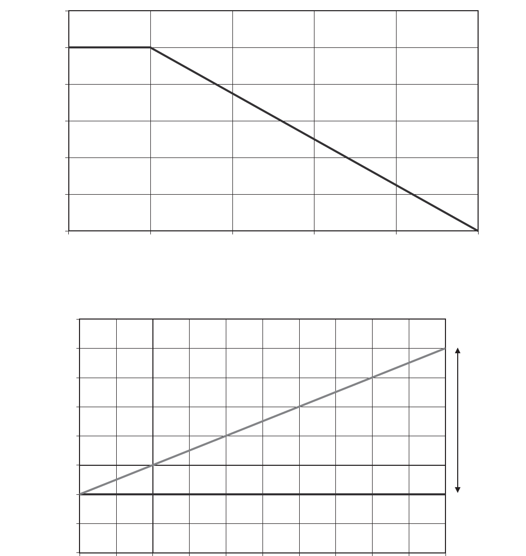
33
0
1
2
3
4
5
6
0186420
COOLER FLUID TEMPERATURE DIFFERENCE (deg F)
DEGREES RESET (deg F)
(EXAMPLE)
Fig. 15 — Water Temperature Difference Reset
0
4
2
4
44
64
8
4
05
2
5
45
65
0010908070605
0
40
3
0
2
0
1
0
LOADING (%)
FLUID TEMPERATURE (deg F)
DESIGN
RISE
(TYPICAL)
LWT
EWT
LEGEND
Fig. 16 — Chilled Water Temperature Control
EWT — Entering Water Temperature
LWT — Leaving Water Temperature

34
0
2
4
6
8
01
21
41
61
021001080604020
OUTDOOR TEMPERATURE (F)
RESET AMOUNT (deg F)
(EXAMPLE)
Fig. 17 — Outdoor Air Temperature Reset

35
Table 29 — Water Temperature Difference Reset Configuration
NOTE: Bold values indicate sub-mode level.
MODE KEYPAD ENTRY DISPLAY ITEM EXPANSION COMMENT
CONFIGURATION
DISP
UNIT
SERV
OPTN
RSET Reset Cool and Heat Tmp
CRST Cooling Reset Type
0 No Reset
0 No Reset Flashing to indicate Edit mode. May require Password
/ 2 Delta T Temp Use up or down arrows to change value to 2.
2 Accepts the change.
CRST
At mode level
SETPOINTS
/ Change to Setpoints Mode
COOL Cooling Setpoints
CSP.1 Cooling Setpoint 1
x 4 CRV.2
CRT1 Delta T No Reset Temp Cooler Temperature difference where no temperature
reset is required.
0 Value of CRT1
0 Flashing to indicate Edit mode
10.0 Value of No Temperature Reset, 10 from the example.
10.0 Accepts the change.
CRT1
CRT2 Delta T Full Reset Temp Cooler Temperature difference where full temperature
reset, DGRC is required.
0 Value of CRT2.
0 Flashing to indicate Edit mode
2.0 Value of full Temperature Reset, 2 from the example.
2.0 Accepts the change.
CRT2
x 4 CRS2
DGRC Degrees Cool Reset Amount of temperature reset required.
0 Value of DGRC
0 Flashing to indicate Edit mode
5.0
Amount of Temperature Reset required, 5 from the example.
5.0 Accepts the change.
DGRC
ENTER
ENTER
ENTER
ENTER
ENTER
ESCAPE
ESCAPE
ENTER
ENTER
ENTER
ENTER
ENTER
ESCAPE
ENTER
ENTER
ENTER
ESCAPE
ENTER
ENTER
ENTER
ESCAPE

36
Table 30 — OAT Reset Configuration
NOTE: Bold values indicate sub-mode level.
MODE KEYPAD ENTRY DISPLAY ITEM EXPANSION COMMENT
CONFIGURATION
DISP
UNIT
SERV
OPTN
RSET Reset Cool and Heat Tmp
CRST Cooling Reset Type
0 No Reset
0 No Reset Flashing to indicate Edit mode. May require Password
/ 1 Out Air Temp Use up or down arrows to change value to 1.
1 Accepts the change.
CRST
At mode level
SETPOINTS
/ Change to Setpoints Mode
COOL Cooling Setpoints
CSP.1 Cooling Setpoint 1
x 6 CRT.2
CRO1 OAT No Reset Temp Outdoor Temperature where no temperature reset is
required.
0 Value of CRO1
0 Flashing to indicate Edit mode
85.0 Value of No Temperature Reset, 85 from the example.
85.0 Accepts the change.
CRO1
CRO2 OAT Full Reset Temp Outdoor Temperature where full temperature reset,
DGRC is required.
0 Value of CRO2.
0 Flashing to indicate Edit mode
55.0 Value of full Temperature Reset, 55 from the example.
55.0 Accepts the change.
CRO2
CRS1
CRS2
DGRC Degrees Cool Reset Amount of temperature reset required.
0 Value of DGRC
0 Flashing to indicate Edit mode
10.0 Amount of Temperature Reset required, 10 from the
example.
10.0 Accepts the change.
DGRC
ENTER
ENTER
ENTER
ENTER
ENTER
ESCAPE
ESCAPE
ENTER
ENTER
ENTER
ENTER
ENTER
ESCAPE
ENTER
ENTER
ENTER
ESCAPE
ENTER
ENTER
ENTER
ESCAPE

37
To use Space Temperature Reset in addition to the energy
management module, four variables must be configured. They
are: Cooling Reset Type (ConfigurationRSETCRST),
Space T No Reset Temp (SetpointsCOOLCRS1), Space
T Full Reset Temp (SetpointsCOOLCRS2) and Degrees
Cool Reset (SetpointsCOOLDGRC). In the following
space temperature reset example, 0° F (0° C) chilled water set
point reset at 72.0 F (22.2 C) space temperature and 6.0° F
(3.3° C) reset at 68.0 F (20.0 C) space temperature. See Fig. 18
and Table 31.
To use 4-20 mA Temperature Reset in addition to the ener-
gy management module, four variables must be configured.
They are: Cooling Reset Type (ConfigurationRSET
CRST), Current No Reset Val (SetpointsCOOLCRV1),
Current Full Reset Val (SetpointsCOOLCRV2) and
Degrees Cool Reset (SetpointsCOOLDGRC). In the
following example, at 4 mA no reset takes place. At 20 mA,
5° F (2.8° C) chilled water set point reset is required. See
Fig. 19 and Table 32.
CAUTION
Care should be taken when interfacing with other control
systems due to possible power supply differences such as a
full wave bridge versus a half wave rectification. Connec-
tion of control devices with different power supplies may
result in permanent damage. ComfortLink controls incor-
porate power supplies with half wave rectification. A sig-
nal isolation device should be utilized if the signal
generator incorporates a full wave bridge rectifier.
SPACE TEMPERATURE (F)
DEGREES RESET (deg F)
60
62
64
66
68
70
72
74
76
78
80
0
1
2
3
4
5
6
7
(EXAMPLE)
mA SIGNAL
DEGREES RESET (deg F)
20 4 6 8 10 12 14 16 18 20
0
1
2
3
4
5
6
Fig. 18 — Space Temperature Reset
Fig. 19 — 4 to 20 mA Temperature Reset

38
Table 31 — Space Temperature Reset Configuration
NOTE: Bold values indicate sub-mode level.
MODE KEYPAD ENTRY DISPLAY ITEM EXPANSION COMMENT
CONFIGURATION
DISP
UNIT
SERV
OPTN
RSET Reset Cool and Heat Tmp
CRST Cooling Reset Type
0 No Reset
0 No Reset Flashing to indicate Edit mode. May require Password
/ 4 Space Temp Use up or down arrows to change value to 4.
4 Accepts the change.
CRST
At mode level
SETPOINTS
/ Change to Setpoints Mode
COOL Cooling Setpoints
CSP.1 Cooling Setpoint 1
x 8 CRO2
CRS1 Space T No Reset Temp Space Temperature where no temperature reset is
required.
0 Value of CRS1
0 Flashing to indicate Edit mode
72.0 Value of No Temperature Reset, 72 from the example.
72.0 Accepts the change.
CRS1
CRS2 Space T Full Reset Temp Space Temperature where full temperature reset,
DGRC is required.
0 Value of CRS2.
0 Flashing to indicate Edit mode
68.0 Value of full Temperature Reset, 68 from the example.
68.0 Accepts the change.
CRS2
DGRC Degrees Cool Reset Amount of temperature reset required.
0 Value of DGRC
0 Flashing to indicate Edit mode
6.0 Amount of Temperature Reset required, 6 from the
example.
6.0 Accepts the change.
DGRC
ENTER
ENTER
ENTER
ENTER
ENTER
ESCAPE
ESCAPE
ENTER
ENTER
ENTER
ENTER
ENTER
ESCAPE
ENTER
ENTER
ENTER
ESCAPE
ENTER
ENTER
ENTER
ESCAPE

39
Table 32—4to20mATemperature Reset Configuration
NOTE: Bold values indicate sub-mode level.
MODE KEYPAD ENTRY DISPLAY ITEM EXPANSION COMMENT
CONFIGURATION
DISP
UNIT
SERV
OPTN
RSET Reset Cool and Heat Tmp
CRST Cooling Reset Type
0 No Reset
0 No Reset Flashing to indicate Edit mode. May require Password
/ 3 4-20 mA Input Use up or down arrows to change value to 3.
3 Accepts the change.
CRST
At mode level
SETPOINTS
/ Change to Setpoints Mode
COOL Cooling Setpoints
CSP.1 Cooling Setpoint 1
x 2 CSP.3 Cooling Setpoint 3
CRV1 Current No Reset Val Outdoor Temperature where no temperature reset is
required.
0 Value of CRV1
0 Flashing to indicate Edit mode
4.0 Value of No Temperature Reset, 4 from the example.
4.0 Accepts the change.
CRV1
CRV2 Current Full Reset Val Current value where full temperature reset, DGRC is
required.
0 Value of CRV2.
0 Flashing to indicate Edit mode
20.0 Value of full Temperature Reset, 20 from the example.
20.0 Accepts the change.
CRV2
x 6 CRS2
DGRC Degrees Cool Reset Amount of temperature reset required.
0 Value of DGRC
0 Flashing to indicate Edit mode
5.0 Amount of Temperature Reset required, 5 from the
example.
5.0 Accepts the change.
DGRC
ENTER
ENTER
ENTER
ENTER
ENTER
ESCAPE
ESCAPE
ENTER
ENTER
ENTER
ENTER
ENTER
ESCAPE
ENTER
ENTER
ENTER
ESCAPE
ENTER
ENTER
ENTER
ESCAPE

40
Demand Limit — Demand limit is a feature that allows
the unit capacity to be limited during periods of peak energy
usage. Once a Demand Limit command has been initiated, the
unit capacity will be limited to the commanded value and will
not exceed that value.
Three types of demand limiting are available on the 30RB
units. The first type is through switch control, which will re-
duce the maximum capacity by up to three user-configurable
percentages. Single-Step Switch Control Demand Limit is
standard on all 30RB units. To utilize Two and Three-Step
Switch Control Demand Limit, the Energy Management Mod-
ule is required. The second type of demand limiting is by 4 to
20 mA signal input, which will reduce the maximum capacity
linearly from 100% at a 4 mA input signal (no reduction) down
to the user-configurable level at a 20 mA input signal. To uti-
lize 4 to 20 mA Demand Limit, the Energy Management Mod-
ule is required. The third type of demand limiting requires a
programmable controller (Open or CCN) or UPC, and writes a
demand limit directly to the control.
Using the scrolling marquee, the Active Demand Limit Val
(Run StatusVIEWLIM) will display the current demand
limit value. A value of 100 will allow the machine to run fully
loaded if required. Any value less than 200 will limit the capac-
ity of the machine.
To use demand limit, select the type of demand limiting to
use. Then configure the demand limit set points based on the
type selected.
SWITCH CONTROLLED — Single-Step Switch Control
Demand Limit is standard on all 30RB units. To utilize Two or
Three-Step Switch Control Demand Limit, the Energy Man-
agement Module is required. The three steps are achieved
through two sets of dry contacts. The contacts for Demand
Limit Switch 1 must be connected to TB5-5, 14. The contacts
for Demand Limit Switch 2 must be connected to TB6-14,15.
See Fig. 20.
Several parameters must be configured for switch con-
trolled demand limit:
• Demand Limit Select (ConfigurationRSETDMDC)
• Switch Limit Setpoint 1 (SetpointsMISCDLS1)
• Switch Limit Setpoint 2 (SetpointsMISCDLS2), if
Two-Step Switch Control is desired
• Switch Limit Setpoint 3 (SetpointsMISCDLS3), if
Three-Step Switch Control is desired
The position of the Demand Limit Switch contacts shown in
Fig. 20 will allow for up to three steps of demand limit accord-
ing to Table 33.
The actual positions of Demand Limit Switches 1 and 2
seen by the control can be viewed using the scrolling marquee
or Navigator
™
display by accessing the items
InputsGEN.1DLS1 or InputsGEN.1DLS2.
Follow the example in Table 34 to enable the function and
configure the step demand limit for 80%, 60%, and 25% capac-
ity limit based on the switch position described above.
Table 33 — Demand Limit Switch Status Reponse
SWITCH STATUS
DEMAND LIMIT VALUE
SCROLLING MARQUEE/NAVIGATOR DISPLAY ITEM
Demand Limit
Switch 1
Demand Limit
Switch 2
Open Open None
Closed Open SetpointsMISCDLS1
Open Closed SetpointsMISCDLS2
Closed Closed SetpointsMISCDLS3
MAIN
BASE
BOARD
J4
EMM
BOARD
J4
Fig. 20 — Switch Controlled Demand Limit Wiring
a30-5710

41
Table 34 — Switch Controlled Demand Limit (Scrolling Marquee and Navigator
™
Display)
In the example in Table 34, when Demand Limit Switch 1
is closed and Demand Limit Switch 2 is open, the maximum
chiller capacity will be reduced to 80%. When Demand Limit
Switch 1 is open and Demand Limit Switch 2 is closed, the
maximum chiller capacity will be reduced to 60%. Similarly,
when both Demand Limit Switches are closed, the maximum
chiller capacity will be reduced to 25%.
EXTERNALLY POWERED (4 to 20 mA Controlled) —
The Energy Management Module is required for 4 to 20
mA demand limit control. The 4 to 20 mA positive signal is
connected to TB6-1 and the negative to TB6-2. Additionally, a
field-supplied 250-ohm,
1
/
2
-watt resistor must be installed
across TB6-1 and TB6-2. See Fig. 21. The Energy Manage-
ment Module accepts a 0 to 5 vdc input. The resistor converts
the 4 to 20 mA signal to a 0 to 5 vdc input.
The input signal seen by the control can be viewed using the
scrolling marquee or Navigator display by accessing the item
InputsGEN.1DMND.
To configure demand limit for 4 to 20 mA control, three pa-
rameters must be configured:
• Demand Limit Select
(ConfigurationRSETDMDC)
• mA for 100% Demand Limit
(ConfigurationRSETDMMX)
• mA for 0% Demand Limit
(ConfigurationRSETDMZE).
In the following example, a 4 mA signal is Demand Limit
100% and a 20 mA Demand Limit signal is 0%. The demand
limit is a linear interpolation between the two values entered.
See Table 35 and Fig. 22. In Fig. 22, if the machine receives a
12 mA signal, the machine controls will limit the capacity to
50%.
Table 35—4to20mADemandLimit(Scrolling Marquee and Navigator Display)
ITEM EXPANSION PATH
SCROLLING MARQUEE
NAVIGATOR
DISPLAY
Value Expansion
DMDC Demand Limit Select ConfigurationRSET 1 Switch Switch
DLS1 Switch Limit Setpoint 1 SetpointsMISC 80 — 80
DLS2 Switch Limit Setpoint 2 SetpointsMISC 60 — 60
DLS3 Switch Limit Setpoint 3 SetpointsMISC 25 — 25
EMM
BOARD
J7B
Fig. 21 — 4 to 20 mA Demand Limit Input Wiring
a30-5711
CAUTION
Care should be taken when interfacing with other control
systems due to possible power supply differences such as a
full wave bridge versus a half wave rectification. Connec-
tion of control devices with different power supplies may
result in permanent damage. ComfortLink controls incor-
porate power supplies with half wave rectification. A sig-
nal isolation device should be utilized if the signal
generator incorporates a full wave bridge rectifier.
ITEM EXPANSION PATH
SCROLLING MARQUEE
NAVIGATOR
DISPLAY
Value Expansion
DMDC Demand Limit Switch ConfigurationRSET 2 4-20 mA Input 4-20 mA Input
DMMX mA for 100% Demand Lim ConfigurationRSET 4— 4
DMZE mA for 0% Demand Lim ConfigurationRSET 20 — 20
0
01
02
03
04
05
06
07
08
09
001
0281614
1
210
1
8642
0
DEMAND LIMIT SIGNAL (mA)
DEMAND LIMIT (%)
22
Fig. 22 — Demand Limit Response to mA Signal
42
CCN CONTROLLED — To configure demand limit for CCN
control, the unit Operating Type Control must be in CCN con-
trol (Operating ModesSLCTOPER=2), and must be con-
trolled by a programmable controller (Open or CCN) or UPC.
By writing to the CCN point DEM_LIM (Status Display Table
GENUNIT), the unit capacity can be controlled.
Remote Alarm and Alert Relays — The 30RB
chiller can be equipped with a remote alert and remote alarm
annunciator contacts. Both relays connected to these contacts
must be rated for a maximum power draw of 10 va sealed,
25 va inrush at 24 volts. The alarm relay, indicating that the
complete unit has been shut down can be connected to TB5-12
and TB5-13. For an alert relay, indicating that at least 1 circuit
was off due to the alert, a field-supplied and installed relay
must be connected between MBB-J3-CH25-3 and TB5-13.
Broadcast Configuration — The 30RB chiller is ca-
pable of broadcasting time, date, and holiday status to all ele-
ments in the CCN system. In the stand-alone mode, broadcast
must be activated to utilize holiday schedules and adjust for
daylight saving time. If the chiller is to be connected to a CCN
system, determine which system element is to be the network
broadcaster to all other system elements. Broadcast is activated
and deactivated in the BRODEFS Table. It is accessible
through Network Service Tool. It is not accessible through the
scrolling marquee display.
Only one element should be configured as a broadcaster. If
a broadcast is activated by a device that has been designated as
a network broadcaster, then broadcasted time, date, and holiday
status will be updated over the CCN system. If broadcast is en-
abled, a broadcast acknowledger must also be enabled. The
acknowledger cannot be the same machine as the broadcasting
machine.
ACTIVATE — The Activate variable enables the broadcast
function of the ComfortLink controls. If this variable is set to 0,
this function is not used and holiday schedules and daylight
savings compensation are not possible. Setting this variable to
1 allows the machine to broadcast and receive broadcasts on
the network. The following information is broadcast: the time
with compensation for daylight savings, date, and holiday flag.
Set this variable to 2 for stand-alone units that are not con-
nected to a CCN. With this configuration, daylight saving time
and holiday determination will be done without broadcasting
through the bus. This variable can only be changed when using
ComfortVIEW™ software or Network Service Tool. This vari-
able cannot be changed with the scrolling marquee display.
BROADCAST ACKNOWLEDGER — This configuration
defines if the chiller will be used to acknowledge broadcast
messages on the CCN bus. One broadcast acknowledger is
required per bus, including secondary buses created by the use
of a bridge. This variable can only be changed with Comfort-
VIEW software or Network Service Tool. This variable cannot
be changed with the scrolling marquee display.
Alarm Control
ALARM ROUTING CONTROL — Alarms recorded on the
chiller can be routed through the CCN. To configure this op-
tion, the ComfortLink control must be configured to determine
which CCN elements will receive and process alarms. Input for
the decision consists of eight digits, each of which can be set to
either 0 or 1. Setting a digit to 1 specifies that alarms will be
sent to the system element that corresponds to that digit. Set-
ting all digits to 0 disables alarm processing. The factory de-
fault is 00000000. See Fig. 23. The default setting is based on
the assumption that the unit will not be connected to a network.
If the network does not contain a ComfortVIEW, Comfort-
WORKS
®
, TeLink, DataLINK™, or BAClink module, en-
abling this feature will only add unnecessary activity to the
CCN communication bus.
This option can be modified with Network Service Tool. It
cannot be modified with the scrolling marquee display.
Typical configuration of the Alarm Routing variable is
11010000. This Alarm Routing status will transmit alarms to
ComfortVIEW software, TeLink, BAClink, and DataLINK.
ALARM EQUIPMENT PRIORITY — The ComfortVIEW
software uses the equipment priority value when sorting alarms
by level. The purpose of the equipment priority value is to de-
termine the order in which to sort alarms that have the same
level. A priority of 0 is the highest and would appear first when
sorted. A priority of 7 would appear last when sorted. For ex-
ample, if two chillers send out identical alarms, the chiller with
the higher priority would be listed first. The default is 4. This
variable can only be changed when using ComfortVIEW soft-
ware or Network Service Tool. This variable cannot be
changed with the scrolling marquee display.
COMMUNICATION FAILURE RETRY TIME — This
variable specifies the amount of time that will be allowed to
elapse between alarm retries. Retries occur when an alarm is
not acknowledged by a network alarm acknowledger, which
may be either a ComfortVIEW software or TeLink. If ac-
knowledgement is not received, the alarm will be re-transmit-
ted after the number of minutes specified in this decision. This
variable can only be changed with ComfortVIEW software or
Network Service Tool. This variable cannot be changed with
the scrolling marquee display.
RE-ALARM TIME — This variable specifies the amount of
time that will be allowed to elapse between re-alarms. A re-
alarm occurs when the conditions that caused the initial alarm
continue to persist for the number of minutes specified in this
decision. Re-alarming will continue to occur at the specified
interval until the condition causing the alarm is corrected. This
variable can only be changed with ComfortVIEW software or
Network Service Tool. This variable cannot be changed with
the scrolling marquee display.
ALARM SYSTEM NAME — This variable specifies the
system element name that will appear in the alarms generated
by the unit control. The name can be up to 8 alphanumeric
characters in length. This variable can only be changed with
ComfortVIEW software or Network Service Tool. This vari-
able cannot be changed with the scrolling marquee display.

43
PRE-START-UP
Do not attempt to start the chiller until the following checks
have been completed.
System Check
1. Check auxiliary components, such as the chilled fluid
circulating pump, air-handling equipment, or other
equipment to which the chiller supplies liquid are opera-
tional. Consult manufacturer’s instructions. If the unit has
field-installed accessories, be sure all are properly
installed and wired correctly. Refer to unit wiring
diagrams.
2. Open compressor suction (if equipped) and discharge
shutoff valves.
3. Open liquid line shutoff valves.
4. Fill the chiller fluid circuit with clean water (with recom-
mended inhibitor added) or other non-corrosive fluid to
be cooled. Bleed all air out of high points of system. An
air vent pipe plug is included with the cooler. If outdoor
temperatures are expected to be below 32 F (0° C), suffi-
cient inhibited propylene glycol or other suitable corro-
sion inhibited antifreeze should be added to the chiller
water circuit to prevent possible freeze-up.
The chilled water loop must be cleaned before the unit is
connected. Units supplied with the accessory hydronic
package include a run in screen. If the run-in screen is left
in the suction guide/strainer, it is recommended that the
Service Maintenance be set to alert the operator within
24 hours of start-up to be sure that the run-in screen in the
suction guide/strainer is removed. To set the time for the
parameter, go to Time ClockMCFGW.FIL. Values
for this item are counted as days. Refer to the hydronic
pump package literature if unit is equipped with the
optional hydronic pump package.
5. Check tightness of all electrical connections.
6. Oil should be visible in the compressor sight glass. An
acceptable oil level in the compressor is from
3
/
4
to
7
/
8
full sight glass. Adjust the oil level as required. No oil
should be removed unless the crankcase heater has been
energized for at least 24 hours. See Oil Charge section for
Carrier-approved oils.
7. Electrical power source must agree with unit nameplate.
8. Crankcase heaters must be firmly seated under compres-
sor, and must be energized for 24 hours prior to start-up.
9. Verify power supply phase sequence. Check reverse rota-
tion board. If lower (red) LED is blinking, the phase se-
quence is incorrect. Reverse two of the power wires at the
main terminal block. Units with dual power point connec-
tion utilize two reverse rotation boards. Check both for
proper phase sequence.
10. Check compressors and compressor mounting sled. Com-
pressor shipping braces and shipping bolts must be re-
moved.
START-UP
Actual Start-Up —
Actual start-up should be done only
under supervision of a qualified refrigeration technician.
1. Be sure all shut off valves are open. Units are shipped
from factory with suction valves (if equipped) open.
Discharge and liquid line shut off valves are closed.
2. Using the scrolling marquee display, set leaving-fluid set
point (SetpointsCOOLCSP.1). No cooling range ad-
justment is necessary.
3. If optional control functions or accessories are being
used, the unit must be properly configured. Refer to
Configuration Options section for details.
4. Start chilled fluid pump, if unit is not configured for
pump control, (ConfigurationOPTNPUMP= 0).
5. Complete the Start-Up Checklist to verify all components
are operating properly.
6. Turn ENABLE/OFF/REMOTE CONTACT switch to
ENABLE position.
7. Allow unit to operate and confirm that everything is
functioning properly. Check to see that leaving fluid
temperature agrees with leaving set point Control Point
(Run StatusVIEWCTPT).
DESCRIPTION STATUS POINT
Alarm Routing 0 0 0 0 0 0 0 0 ALRM_CNT
ComfortView™, or ComfortWorks
TeLink
Unused
BacLink or DataLink™
Unused
®
a30-4485
Fig. 23 — Alarm Routing Control
IMPORTANT: Complete the Start-Up Checklist
for 30RB Liquid Chillers at the end of this publication.
The checklist assures proper start-up of a unit, and
provides a record of unit condition, application
requirements, system information, and operation at
initial start-up.
CAUTION
Do not manually operate contactors. Serious damage to the
machine may result.

44
Operating Limitations
TEMPERATURES — Unit operating temperature limits are
listed in Table 36.
Table 36 — Temperature Limits for Standard Units
LEGEND
*For sustained operation, EWT should not exceed 85 F (29.4 C).
†Unit requires brine modification for operation below this
temperature.
Low Ambient Operation — If unit operating temperatures be-
low 32 F (0° C) are expected, refer to separate unit installation
instructions for low ambient temperature operation using ac-
cessory low ambient temperature head pressure control, if not
equipped. Contact a Carrier representative for details.
NOTE: Wind baffles and brackets must be field-fabricated and
installed for all units using accessory low ambient head
pressure control to ensure proper cooling cycle operation at
low-ambient temperatures. See the 30RB Installation
Instructions or the low ambient temperature head pressure con-
trol accessory installation instructions for more information.
VOLTAGE
Main Power Supply — Minimum and maximum acceptable
supply voltages are listed in the Installation Instructions.
Unbalanced 3-Phase Supply Voltage — Never operate a
motor where a phase imbalance between phases is greater than
2%.
To determine percent voltage imbalance:
The maximum voltage deviation is the largest difference
between a voltage measurement across 2 legs and the average
across all 3 legs.
Example: Supply voltage is 240-3-60.
AB = 243v
BC = 236v
AC = 238v
1. Determine average voltage:
2. Determine maximum deviation from average voltage:
(AB) 243 – 239 = 4 v
(BC) 239 – 236 = 3 v
(AC) 239 – 238 = 1 v
Maximum deviation is 4 v.
3. Determine percent voltage imbalance:
= 1.7%
This voltage imbalance is satisfactory as it is below the
maximum allowable of 2%.
MINIMUM FLUID LOOP VOLUME — To obtain proper
temperature control, loop fluid volume must be at least 3 gal-
lons per ton (3.25 L per kW) of chiller nominal capacity for air
conditioning and at least 6 gallons per ton (6.5 L per kW) for
process applications or systems that must operate at low ambi-
ent temperatures (below 32 F [0° C]). Refer to application in-
formation in Product Data literature for details.
FLOW RATE REQUIREMENTS — Standard chillers
should be applied with nominal flow rates within those listed in
the Minimum and Maximum Cooler Flow Rates table. Higher
or lower flow rates are permissible to obtain lower or higher
temperature rises. Minimum flow rates must be exceeded to
assure turbulent flow and proper heat transfer in the cooler. See
Table 37.
Consult application data section in the Product Data
literature and job design requirements to determine flow rate
requirements for a particular installation.
TEMPERATURE F C
Maximum Ambient Temperature 125 52
Minimum Ambient Temperature 32 0
Maximum Cooler EWT* 95 35
Maximum Cooler LWT 60 15
Minimum Cooler LWT† 40 4.4
EWT — Entering Fluid (Water) Temperature
LWT — Leaving Fluid (Water) Temperature
CAUTION
Brine duty application (below 40 F [4.4 C] leaving
chilled water temperature) for chiller normally requires
factory modification. Contact your Carrier representa-
tive for details regarding specific applications. Oper-
ation below 40 F (4.4 C) leaving chilled water
temperature without modification can result in
compressor failure.
% Voltage Imbalance = 100 x
max voltage deviation from
avg voltage
average voltage
Average voltage =
243+236+238
3
=
717
3
= 239
% Voltage Imbalance = 100 x
4
239
IMPORTANT: If the supply voltage phase imbalance
is more than 2%, contact the local electric utility com-
pany immediately. Do not operate unit until imbalance
condition is corrected.
CAUTION
Operation below minimum flow rate could subject tubes to
frost pinching in the tube sheet, resulting in failure of the
cooler.

45
Table 37 — Minimum and Maximum Cooler Flow Rates
SIZES 060-300
SIZES 315-390
OPERATION
Sequence of Operation —
With a command to start
the chiller, the cooler pump will start. After verifying water
flow, the control will monitor the entering and leaving water
temperature. At any time that a compressor is not operating, its
crankcase heater is active. If the need for mechanical cooling is
determined, the control decides which circuit and compressor
to start. The compressor will deenergize the crankcase heater as
it starts. Compressors will be staged with minimum load
control (if equipped and configured) to maintain LWT set
point.
Shutdown of each circuit under normal conditions occurs in
increments, starting with the minimum load control (if
equipped) and finishing with the last running compressor. Once
minimum load control is disabled, one compressor is
shut down. Eight seconds later the next compressor will
shut down. The process will continue until all of the compres-
sors are shut down. The EXV will close completely, 1 minute
after the last compressor has shut down. There are several
abnormal conditions that, if detected, will shut down the circuit
immediately. In this case, minimum load control and all
compressors are turned off without an 8-second interval
between them. The cooler pump will remain ON for 20 sec-
onds after the last compressor has been turned OFF.
Dual Chiller Sequence of Operation — With a
command to start the chiller, the master chiller determines
which chiller will become the lead chiller based on Configura-
tionRSETLLBL and Configuration RSETLLBD.
The lead chiller is always started first and the lag chiller is held
at zero percent capacity by the master chiller forcing the lag de-
mand limit value to 0%. The lead chiller’s water pump will be
started. The lag chiller’s water pump shall be maintained off if
ConfigurationRSETLAGP=0. The internal algorithm of
lead chiller will control capacity of the lead chiller.
If Lead Pulldown Time (ConfigurationRSETLPUL)
has been configured, the lead chiller will continue to operate
alone for that specified time. After the Lead Pulldown Time
timer has elapsed, if the lead chiller is fully loaded and either
all available compression is on or at the master demand limit
value, then the lag start timer (ConfigurationRSET
LLDY) is initiated. When the pulldown timer and lag start
timer have elapsed and the Combined Leaving Chilled Water
Temperature is more than 3° F (1.7° C) above the set point,
then the lag chiller is started.
If the lag chiller’s water pump was not started when the ma-
chines went into occupied mode, then the lag chiller water
pump will be started. The lag chiller will start when the master
chiller forcing the lag chiller demand limit value (LAG_LIM)
to the master’s demand limit value. If lead/lag capacity balance
is selected, once the lag chiller has started, the master chiller
will try to keep the difference in capacity between lead and lag
to less than 20%. The master chiller will then be responsible for
water loop capacity calculation, and will determine which
chiller, the lead or lag, will increase or decrease capacity. When
the load reduces, the lag chiller will unload first. To accomplish
this, the lead chiller set point is decreased by 4° F (–2.2° C)
until the lag chiller unloads.
To configure the two chillers for dual chiller operation,
the master chiller must have the Control Method variable (Op-
erating ModeSLCTOPER) set to meet the job require-
ments. The slave chiller must be set to Control Method variable
(Operating ModeSLCTOPER) = 2 (CCN Control) and
the remote-off-enable switch must be in the enable position.
The master chiller and the slave chiller CCN addresses (Con-
figurationOPTNCCNA) must be configured. The master
30RB
SIZE
MINIMUM
COOLER
FLOW RATE
(gpm)
MAXIMUM
FLOW RATE
(gpm)
MINIMUM
LOOP
VOLUME
(gal.)
MINIMUM COOLER
FLOW RATE
(l/s)
MAXIMUM
COOLER
FLOW RATE
(l/s)
MINIMUM
LOOP
VOLUME
(liters)
060 72 288 180 5 18 681
070 84 336 210 5 21 795
080 96 384 240 6 24 908
090 108 432 270 7 27 1022
100 120 480 300 8 30 1136
110 132 528 330 8 33 1249
120 144 576 360 9 36 1363
130 156 624 390 10 39 1476
150 180 720 450 11 45 1703
160 192 768 480 12 48 1817
170 204 816 510 13 51 1931
190 228 912 570 14 58 2158
210 252 950 630 16 60 2385
225 270 950 675 17 60 2555
250 300 950 750 19 60 2839
275 330 950 825 21 60 3123
300 360 950 900 23 60 3407
30RB
SIZE
MINIMUM COOLER
FLOW RATE
(gpm)
MAXIMUM COOLER
FLOW RATE
(gpm)
MIN
LOOP
VOLUME
(gal.)
MINIMUM COOLER
FLOW RATE
(l/s)
MAXIMUM COOLER
FLOW RATE
(l/s)
MIN
LOOP
VOLUME
(liters)
Module A Module B Module A Module B Module A Module B Module A Module B
315 192 192 768 768 945 12 12 48 48 3577
330 204 192 816 768 990 12 12 51 48 3748
345 204 204 816 816 1035 13 13 51 51 3918
360 228 204 912 816 1080 14 13 58 51 4088
390 228 228 912 912 1170 14 14 58 58 4429

46
and slave chillers can be addressed from 1 to 239. Each device
connected to the network must have its own unique address.
Both chillers must have the same CCN Bus Number
(ConfigurationOPTNCCNB). Lead/Lag Chiller Enable
must be set for both chillers by configuring Master/Slave
Select (ConfigurationRSETMSSL) to 1 (Master) for the
master chiller. The slave chiller Master/Slave Select must be
set to 2 (Slave). The master chiller can be configured to use
Lead/Lag Balance (ConfigurationRSETLLBL) to rotate
the lead and lag chillers after a configured number of hours of
operation. The Lag Start Delay (Configuration
RSETLLBD) can be configured. This prevents the Lag
chiller from starting until the lead chiller is fully loaded and the
delay has elapsed.
Operating Modes
MODE 1 (Operating ModeMODEMD01) — Startup
Delay in Effect
Criteria for Mode — Tested when the unit is started. This
mode is active when the Minutes Off Time (Configuration
OPTNDELY) timer is active.
Action Taken — The unit will not start until the timer has
expired.
Termination — The mode will terminate when the timer
expires.
Possible Causes — This mode is in effect only due to the Min-
utes Off Time timer.
MODE 2 (Operating ModeMODEMD02) — Second
Setpoint in Use
Criteria for Mode — Tested when the unit is ON. This mode
is active when Cooling Setpoint 2 (SetpointsCOOL
CSP.2) or Ice Setpoint (SetpointsCOOLCSP.3) is in
use. While in this mode, the Active Setpoint (Run Status
VIEWSETP) will show the CSP.2 or CSP.3 value.
Action Taken — The unit will operate to the Cooling Setpoint
2 (CSP.2) or Ice Setpoint (CSP.3).
Termination — This mode will terminate when the Cooling
Setpoint 2 (CSP.2) or Ice Setpoint (CSP.3) is no longer in use.
Possible Causes — This mode is in effect only due to pro-
gramming options.
MODE 3 (Operating ModeMODEMD03) — Reset in
Effect
Criteria for Mode — Tested when the unit is ON. This mode
is active when Temperature Reset (ConfigurationRSET
CRST) is enabled either by CRST=1 (Outside Air Tempera-
ture), CRST=2 (Return Water), CRST=3 (4-20 mA Input), or
CRST=4 (Space Temperature) and is active.
Action Taken — The Active Setpoint (Run StatusVIEW
SETP) will be modified according to the programmed
information and will be displayed as the Control Point (Run
StatusVIEWCTPT).
Termination — This mode will terminate when the Tempera-
ture Reset is not modifying the active leaving water set point,
so SETP is the same as CTPT.
Possible Causes — This mode is in effect only due to pro-
gramming options.
MODE 4 (Operating ModeMODEMD04) — Demand
Limit Active
Criteria for Mode — Tested when the unit is ON. This mode
is active when Demand Limit (ConfigurationRSET
DMDC) is enabled either by DMDC=1 (Switch), DMDC=2
(4-20 mA Input) or the Night Time Low Sound Capacity Limit
(ConfigurationOPTN LS.LT).
Action Taken — The Active Demand Limit Value (Run
StatusVIEWLIM) will display the current demand limit
according to the programmed information and the unit’s capac-
ity will be reduced to the amount shown or lower.
Termination — This mode will terminate when the Demand
Limit command has been removed.
Possible Causes — This mode is in effect when capacity is be-
ing limited by the demand limit function.
MODE 5 (Operating ModeMODEMD05) — Ramp
Loading Active
Criteria for Mode — Tested when the unit is ON. This mode
is active when Ramp Loading (ConfigurationOPTN
RL.S) is enabled and the following conditions are met:
1. The leaving water temperature is more than 4° F (2.2° C)
from the Control Point (Run StatusVIEWCTPT),
and
2. The rate of change of the leaving water temperature is
greater than the Cool Ramp Loading (Set
PointsCOOLCRMP).
Action Taken — The control will limit the capacity step
increase until one of the two conditions in Mode 5 is no longer
true.
Termination — This mode will terminate once both conditions
in Mode 5 are no longer true.
Possible Causes — This mode is in effect only when capacity
is being limited by the ramp loading function.
MODE 6 (Operating ModeMODEMD06) — Cooler
Heater Active
Criteria for Mode — Tested when unit is ON or OFF. This
mode is active when the cooler heater is energized, if the
Outdoor Air Temperature (TemperatureUNITOAT) is
less than the calculated value (Freeze Setpoint + Cooler Heater
Delta T Setpoint [ConfigurationSERVHTR] default
– 2° F [1.1° C]), and either the Leaving Water Temperature
(TemperatureUNITLWT) or the Entering Water Tem-
perature (TemperatureUNITEWT) are less than or equal
to the Freeze Setpoint + Cooler Heater Delta T Setpoint
(HTR).
The Freeze Setpoint is 34 F (1.1 C) for fresh water systems
(ConfigurationSERVFLUD=1). The Freeze Setpoint is
the Brine Freeze Setpoint (ConfigurationSERVLOSP)
for Medium Temperature Brine systems (Configuration
SERVFLUD=2).
Action Taken — The cooler heater will be energized.
Termination — The cooler heater will be deenergized when
both the Entering Water Temperature (EWT) and Leaving
Water Temperature (LWT) are above the Freeze Setpoint +
Cooler Heater Delta T Setpoint (HTR).
Possible Causes — This mode will be enabled for freeze pro-
tection. If the temperatures are not as described above, check
the accuracy of the outside air, entering and leaving water
thermistors.
MODE 7 (Operating ModeMODEMD07) — Water
Pump Rotation
Criteria for Mode — Tested when the unit is ON or OFF. This
mode is active when the Cooler Pump Sequence (Configura-
tionOPTNPUMP) =2 (2 Pumps Automatic Changeover)
and the Pump Rotation Delta Timer (ConfigurationOPTN
ROT.P) has expired.
Action Taken — The control will switch the operation of the
pumps. The lead pump will be operating normally. The lag
pump will be started, becoming the lead, and then the original
lead pump will be shut down.
Termination — This mode will terminate when the pump
operation has been completed.
Possible Causes — This mode is in effect only due to pro-
gramming options.

47
MODE 8 (Operating ModeMODEMD08) — Pump Pe-
riodic Start
Criteria for Mode — This mode is active when the cooler
pump is started for the Periodic Pump Start configuration
(ConfigurationOPTNPM.PS=YES).
Action Taken — If the pump has not run that day, a pump will
be started and will run for 2 seconds at 2:00 PM. If the machine
is equipped with dual pumps, Pump no. 1 will run on even days
(such as day 2, 4, 6 of the month). Pump no. 2 will run on odd
days (such as day 1, 3, 5 of the month).
Termination — This mode will terminate when the pump
shuts down.
Possible Causes — This mode is in effect only due to pro-
gramming options.
MODE 9 (Operating ModeMODEMD09) — Night
Low Noise Active
Criteria for Mode — This mode is active when the Night
Time Low Noise Option has been configured and the time is
within the configured time. Programming a Night Low Noise
Start Time (ConfigurationOPTNLS.ST) and a Night
Low Noise End Time (ConfigurationOPTNLS.ND) con-
figures the option.
Action Taken — The control will raise the head pressure set
point to reduce the number of condenser fans on, thereby
reducing the sound of the machine. Additionally, if the Night
Time Low Sound Capacity Limit (ConfigurationOPTN
LS.LT) has been configured, the units capacity will be limit-
ed to the programmed level.
Termination — This mode will terminate once the Night Low
Noise End Time (LS.ND) has been reached.
Possible Causes — This mode is in effect only due to pro-
gramming options.
MODE 10 (Operating ModeMODEMD10) — System
Manager Active
Criteria for Mode — Tested when the unit is ON or OFF. This
mode is active if a System Manager such as Building Supervi-
sor, Chillervisor System Manager, or another CCN device is
controlling the machine.
Action Taken — The machine will respond to the specific
command received from the System Manager.
Termination — The mode will be terminated if the System
Manager control is released.
Possible Causes — This mode is in effect only due to pro-
gramming options.
MODE 11 (Operating ModeMODEMD11) — Mast
Slave Ctrl Active
Criteria for Mode — Tested if the machine is ON. This mode
is active if the Master Slave Control has been enabled. Having
2 machines programmed, one as the master (Configuration
RSETMSSL=1 [Master]) and the other as a slave
(ConfigurationRSETMSSL=2 [Slave]).
Action Taken — Both the master and slave machine will re-
spond to the capacity control commands issued by the master
controller. This may include control point changes and demand
limit commands.
Termination — This mode will terminate when the Master
Slave Control has been disabled.
Possible Causes — This mode is in effect only due to pro-
gramming options.
MODE 12 (Operating ModeMODEMD12) — Auto
Changeover Active
Criteria for Mode — This mode is not supported for Cooling
Only units.
Action Taken — None.
Termination — None.
Possible Causes — This mode is in effect only due to pro-
gramming options.
MODE 13 (Operating ModeMODEMD13) — Free
Cooling Active
Criteria for Mode — This mode is not supported for Cooling
Only units.
Action Taken — None.
Termination — None.
Possible Causes — This mode is in effect only due to pro-
gramming options.
MODE 14 (Operating ModeMODEMD14) — Re-
claim Active
Criteria for Mode — This mode is not supported for Cooling
Only units.
Action Taken — None.
Termination — None.
Possible Causes — This mode is in effect only due to pro-
gramming options.
MODE 15 (Operating ModeMODEMD15) — Electric
Heat Active
Criteria for Mode — This mode is not supported for Cooling
Only units.
Action Taken — None.
Termination — None.
Possible Causes — This mode is in effect only due to pro-
gramming options.
MODE 16 (Operating ModeMODEMD16) — Heating
Low EWT Lockout
Criteria for Mode — This mode is not supported for Cooling
Only units.
Action Taken — None.
Termination — None.
Possible Causes — This mode is in effect only due to pro-
gramming options.
MODE 17 (Operating ModeMODEMD17) — Boiler
Active
Criteria for Mode — This mode is not supported for Cooling
Only units.
Action Taken — None.
Termination — None.
Possible Causes — This mode is in effect only due to pro-
gramming options.
MODE 18 (Operating ModeMODEMD18) — Ice
Mode in Effect
Criteria for Mode — Tested when the unit is ON. This mode
is active when Ice Setpoint (SetpointsCOOLCSP.3) is
in use. While in this mode, the Active Setpoint (Run Status
VIEWSETP) will show the CSP.3 value.
Action Taken — The unit will operate to the Ice Setpoint
(CSP.3).
Termination — This mode will terminate when the Ice Set-
point (CSP.3) is no longer in use.
Possible Causes — This mode is in effect only due to pro-
gramming options.
MODE 19 Operating ModeMODEMD19) — Defrost
Active on Cir A
MODE 20 (Operating ModeMODEMD20) — Defrost
Active on Cir B
Criteria for Mode — This mode is not supported for Cooling
Only units.
Action Taken — None.

48
Termination — None.
Possible Causes — This mode is in effect only due to pro-
gramming options.
MODE 21 (Operating ModeMODEMD21) — Low
Suction Circuit A
MODE 22 (Operating ModeMODEMD22) — Low
Suction Circuit B
MODE 23 (Operating ModeMODEMD23) — Low
Suction Circuit C
Criteria for Mode — The criteria are tested when the circuit is
ON. The appropriate circuit mode will be active if one of the
following conditions is true:
1. If the circuit’s Saturated Suction Temperature (SST) is
more than 6° F (3.3° C) less than the freeze point and
both the cooler approach (Leaving Water Temperature-
SST) and superheat (Suction Gas Temperature – SST) are
greater than 15° F (8.3° C).
2. If there is more than one compressor ON in the circuit
and the circuit’s SST is greater than 18° F (10.0° C) be-
low the freeze point for more than 90 seconds.
3. If there is more than one compressor ON in the circuit
and the circuit’s SST is greater than –4° F (–20.0° C) and
the SST 30 seconds ago was 18° F (10.0° C) below the
freeze point.
4. If the circuit’s saturated suction temperature is greater
than 6° F (3.3° C) below the freeze point for more than
3 minutes.
For a fresh water system (ConfigurationSERVFLUD
=1), the freeze point is 34° F (1.1° C). For medium temperature
brine systems, (ConfigurationSERVFLUD=2), the freeze
point is Brine Freeze Set Point (ConfigurationSERVLO-
SP).
Action Taken — For criterion 1, no additional stages will be
added. For criteria 2, 3 and 4, one stage of capacity will be
removed.
Termination — The mode will terminate when the circuit’s
Saturated Suction Temperature is greater than the freeze point
minus 6° F (3.3° C) or the circuit has alarmed.
Possible Causes — If this condition is encountered, see Possi-
ble Causes for Alarms P.05, P.06, and P.07 on page 75.
MODE 24 (Operating ModeMODEMD24) — High
DGT Circuit A
MODE 25 (Operating ModeMODEMD25) — High
DGT Circuit B
MODE 26 (Operating ModeMODEMD26) — High
DGT Circuit C
Criteria for Mode — This mode is tested for when any circuit
is running. The circuit saturated condensing and suction tem-
peratures are monitored to ensure that the compressors always
operate withing their allowed “map.” Operation at conditions
at or outside the “map” boundaries will cause this mode to be
in effect. Operation at extremely low suction pressures and
high condensing temperatures will cause the mode to be
generated.
Action Taken — The circuit will not be allowed to increase
capacity and may be automatically unloaded or stopped.
Termination — This mode will terminate when or if the circuit
refrigerant conditions return to within the compressor “map.”
Possible Causes — This mode could be in effect due to a low
fluid flow rate, overcharge of oil in a circuit, dirty condenser
coils, refrigerant overcharge, or excessive brine concentration.
MODE 27 (Operating ModeMODEMD27) — High
Pres Override Cir A
MODE 28 (Operating ModeMODEMD28) — High
Pres Override Cir B
MODE 29 (Operating ModeMODEMD29) — High
Pres Override Cir C
Criteria for Mode — Tested when the circuit is ON. The
appropriate circuit mode will be active if the discharge pressure
for the circuit, Discharge Pressure Circuit A (Pressure
PRC.ADP.A), Discharge Pressure Circuit B (Pres-
surePRC.BDP.B), or Discharge Pressure Circuit C
(PressurePRC.CDP.C) is greater than the High Pressure
Threshold (ConfigurationSERVHP.TH).
Action Taken — The capacity of the affected circuit will be
reduced. If the unit is equipped with Minimum Load Control
and has been configured for High Ambient (Configuration
UNITHGBP=3), the minimum load control valve will be
energized. Two minutes following the capacity reduction, the
circuit’s saturated condensing temperature (SCT) is calculated
and stored. The affected circuit will not be allowed to add ca-
pacity for at least 5 minutes following the capacity reduction. If
after 5 minutes, the circuit’s saturated condensing temperature
is less than SCT – 3° F (1.7° C), if required, another stage of
capacity will be added.
If additional steps of capacity are required, the control will
look for other circuits to add capacity.
Termination — This mode will terminate once the circuit’s
saturated condensing temperature is less than SCT – 3° F
(1.7° C).
Possible Causes — If this condition is encountered, see Possi-
ble Causes for Alarm A1.03. on page 70.
MODE 30 (Operating ModeMODEMD30) — Low
Superheat Circuit A
MODE 31 (Operating ModeMODEMD31) — Low
Superheat Circuit B
MODE 32 (Operating ModeMODEMD32) — Low
Superheat Circuit C
Criteria for Mode — Tested when the circuit is ON with at
least 1 compressor ON. The appropriate circuit mode will be
active is the circuit’s superheat is less than 5° F (2.8° C) or
greater than 45° F (25° C).
Action Taken — No additional stages of circuit capacity will
be added until the circuit’s superheat is greater than 5° F
(2.8° C) and less than 45° F (25° C).
The control will look for other circuits to add capacity if
additional steps of capacity are required.
Termination — This mode will terminate once the affected
circuit’s superheat is greater than 5° F (2.8° C) and less than
45° F (25° C).
Possible Causes — If this condition is encountered, see Possi-
ble Causes for Alarms P.08, P.09, P.10, P.11, P.12 and P.13 on
page 74.
Optional Heat Reclaim Module — The heat re-
claim option adds a water-cooled condenser in parallel with the
standard air-cooled condenser for the purpose of simultaneous-
ly producing tempered hot water while satisfying the chilled
water requirement.
For chillers with the heat reclaim option, Configura-
tion→UNIT→RECL should be set to YES.
This option requires the installation of an additional board
(EMM-HR).
This board allows control of the components shown in Ta-
ble 11. Table 38 lists EMM-HR outputs for the solenoid
valves. Item numbers in Table 38 refer to Fig. 24 of this docu-
ment.
For more control details, refer to the unit low voltage con-
trol schematic (Fig. 25).
The heat reclaim mode can be selected by either the Heat
Recovery Enable Switch or by CCN control.

49
SWITCH CONTROLLED — To configure Heat Reclaim for
SWITCH control, the unit Operating Type Control can be con-
figured to 0, 1 or 2 (Operating Modes→SLCT→OPER). The
Reclaim Select configuration must be set to “Switch Control”
(Operating Modes→SLCT→RL.SE=2). Switch input connec-
tion should be field wired to terminals 14 and 15 on TB7, cool-
ing mode (open) or heat reclaim mode (closed). Switch status
can be accessed through Input→GEN.I→RECL.
CCN CONTROL — To configure Heat Reclaim for CCN
control, the unit Operating Type Control must be set to CCN
control (Operating mode→SLCT→OPER=2). The Reclaim
Select configuration must be set to “Yes” (Operating
Modes→SLCT→RL.SE=1). Heat reclaim mode is selected
by forcing CCN point RECL_SEL (Status Display→
GENUNIT→RECL_SEL) to “NO” for cooling mode or
“YES” for Heat Reclaim mode.
The heat reclaim function is active when the heat reclaim
entering water temperature is lower than the heat reclaim set
point (Setpoints→MISC→RSP), default 122 F (50 C), minus
half or quarter of the heat reclaim deadband, depending on the
number of refrigerant circuits in reclaim mode (Set-
points→MISC→RDB). The default heat reclaim deadband is
9° F (5.0° C) and the recommended deadband range is 5 to
18° F (2.8 to 10° C).
The difference between the reclaim entering water tempera-
ture and reclaim set point will determine if one or two circuits
are required to provide heat reclaim capacity. See Table 39 for
details.
Heat Reclaim Active status is indicated by MODE_14=ON
(Operating Modes→MODE→MD14) from the scrolling mar-
quee display or Mode_14=1 accessed through CCN.
The following is the changeover procedure from cooling
mode to heat reclaim mode.
1. Verify that the circuit has run for more than 2 minutes in
cooling.
2. Start the reclaim pump.
3. Verify the reclaim condenser flow switch is closed. If this
remains open after one minute of condenser pump opera-
tion, the circuit remains in cooling mode and P.15 alarm
will be activated.
Once water flow is established the following conditions
must be true:
• saturated condensing temperature is greater than satu-
rated suction temperature plus 18° F (10° C)
• if reclaim water entering requires the circuit to go to a
heat reclaim session and the number of air cooled to
reclaim changeovers is not greater than 4 per hour
• the last changeover occurred more than 7 minutes ago
When all of these conditions are true, the heat reclaim
pumpdown sequence is activated. During heat reclaim pump-
down, the control will open the entering heat reclaim condens-
er solenoid valve and close the entering air-cooled condenser
solenoid valves 3 seconds later. After one minute or when the
subcooling value is above 13.2 F (-10.4 C), the heat reclaim
operation is effective.
During the heat reclaim operation, if the sub-cooling value
is less than 13.2 F (-10.4 C) leaving air-cooled condenser sole-
noids may activate for 3 seconds every 20 seconds to recover
more charge. If sub-cooling is greater than 16° F (9.0° C) the
entering air cooled condenser solenoids may activate for 3 sec-
onds every 20 seconds to transfer charge back into the air-
cooled condenser to prevent excessive condensing tempera-
ture. The leaving heat reclaim condenser solenoid should re-
main closed.
Once the heat reclaim set point (RSP) is satisfied, the sys-
tem will transition back to normal air-cooled mode. The air-
cooled pumpdown sequence is activated. During air-cooled
pumpdown, the control will open the entering air-cooled con-
denser solenoids and close the entering heat reclaim condenser
valves 3 seconds later.
During the air-cooled operation, leaving heat reclaim con-
denser solenoids may activate for 3 seconds every 20 seconds
to recover more charge into air-cooled operation, based on the
system sub-cooling level. Leaving air-cooled condenser sole-
noids should remain closed.
Heat reclaim entering water temperature (HEWT), leaving
water temperature (HLWT), heat reclaim pump hours
(HR.CD), refrigerant sub-cooling (HRS.x) can be accessed
from the scrolling marquee display through the following
paths:
Temperatures→UNIT→HEWT
Temperature→UNIT→HLWT
Run Status→RUN→HR.CD
Temperatures→Cir.A→HRS.A
Temperatures→Cir.B→HRS.B
To view circuit status through CCN, two points are avail-
able: Reclaim Status Circuit A and Reclaim Status Circuit B.
Each will show a single-digit number as defined in Table 40.
RECLAIM CONDENSER WATER VALVE OUTPUT —
This output (0 to 10 vdc) controls the heat reclaim condenser
3-way water valve position through a variable speed device. A
10 vdc signal corresponds to 100% open.
Table 38 — Heat Reclaim Circuits
OUTPUT ITEM NO. DESCRIPTION CONNECTION RELAY
SOLENOID
TYPE
OPERATION
COOLING RECLAIM
HR1.A 4 Ckt. A Ent A/C Cond. Sol. EMM-J3-CH24 ECA-A N/O OPEN CLOSED
HR2.A 6 Ckt. A Lvg A/C Cond. Sol. EMM-J2-CH18 LCA-A N/C CLOSED CYCLING
HR3.A 2 Ckt. A Ent W/C Cond. Sol. EMM-J2-CH20 ECW-A N/C CLOSED OPEN
HR4.A 9 Ckt. A Lvg W/C Cond. Sol. EMM-J2-CH22 LCW-A N/C CYCLING CLOSED
HR1.B 5 Ckt. B Ent A/C Cond. Sol. EMM-J3-CH25 ECA-B N/O OPEN CLOSED
HR2.B 7 Ckt. B Lvg A/C Cond. Sol. EMM-J2-CH19 LCA-B N/C CLOSED CYCLING
HR3.B 3 Ckt. B Ent W/C Cond. Sol. EMM-J2-CH21 ECW-B N/C CLOSED OPEN
HR4.B 10 Ckt. B Lvg W/C Cond. Sol. EMM-J2-CH23 LCW-B N/C CYCLING CLOSED

50
Table 39 — Heat Reclaim Staging
Table 40 — CCN Table Status Display — RECLAIM
*x=aorb.
The 3-way valve should be installed to facilitate the cold
water start-up below 59 F (15 C) and maintain a stable head
pressure control during heat reclaim operation. The minimum
position of the water valve should be set at 20% and maximum
position should be set at 100%. When the entering water tem-
perature is below 68 F (20 C), the water valve should remain at
20% position to allow a maximum re-circulating of the warm
water between the 3-way water valve and heat reclaim con-
denser.
When the entering water temperature is above 104 F (40 C),
the water valve will remain fully open, allowing no recircula-
tion of the warm water. When the entering water temperature is
between 68 F and 104 F (20 and 40 C), the water valve will be
adjusted between 20% and 100% position in linear proportion
to the value of the entering water temperature.
RECLAIM CONDENSER HEATER OPERATION —
For freeze protection the heat reclaim condenser is equipped
with an electric heater. The heater is energized when entering
or leaving heat reclaim fluid temperature is lower than
37.4 F (3.0 C). The heater is de-energized when both tempera-
tures are above 40.0 F (4.4 C).
HEAT RECLAIM ENTERING WATER TEMPERATURE
RECLAIM
SELECT
NUMBER OF CIRCUITS
IN RECLAIM
NUMBER OF CIRCUITS IN
RECLAIM STATUS CHANGE
–No0-2
hr_ew < rsp - hr_deadb/2 Yes – + 2
rsp - hr_deadb/2 < hr_ewt < rsp - hr_deadb/4 Yes 0 + 1
rsp - hr_deadb/2 < hr_ewt < rsp - hr_deadb/4 Yes 1 Unchanged
rsp - hr_deadb/4 < hr_ewt < rsp + hr_deadb/4 Yes – Unchanged
rsp + hr_deadb/4 < hr_ewt < rsp + hr_deadb/2 Yes 1 Unchanged
rsp + hr_deadb/4 < hr_ewt < rsp + hr_deadb/2 Yes 2 - 1
hr_ewt > rsp + hr_deadb/2 Yes – - 2
RECLAIM STATUS
(hrstat_x)*
DESCRIPTION
0 Air cooled mode
1 Reclaim mode request
2 Reclaim pumpdown sequence
3 Reclaim operation mode
4 Air cooled mode request

51
6
12
13
15
17
18
18
11
10
8
7
8
1
35
4
2
16
14
11
9
8
8
1
19
19
LEGEND
ITEM NUMBERS
EXV — Electronic Expansion Valve
1—Air condenser (coils)
2—Solenoid valve: Heat reclaim mode ckt A (entering heat reclaim condenser)
3—Solenoid valve: Heat reclaim mode ckt B (entering heat reclaim condenser)
4—Solenoid valve: Cooling mode ckt A (entering air-cooled condenser)
5—Solenoid valve: Cooling mode ckt B (entering air-cooled condenser)
6—Solenoid valve: Charge recovery in heat reclaim mode ckt A (leaving air-cooled condenser)
7—Solenoid valve: Charge recovery in heat reclaim mode ckt B (leaving air-cooled condenser)
8—Check valve
9—Solenoid valve: Charge recovery in cooling mode ckt A (leaving heat reclaim condenser)
10 — Solenoid valve: Charge recovery in cooling mode ckt B (leaving heat reclaim condenser)
11 — Compressor
12 — Hot Gas Bypass ckt A
13 — Hot Gas Bypass ckt B
14 — Pumpdown pressure transducer ckt A
15 — Pumpdoiwn pressure transducer ckt B
16 — Subcooled condenser gas temperature ckt A
17 — Subcooled condenser gas temperature ckt B
18 — Expansion Device (EXV)
19 — Filter Drier (FD)
Fig. 24 — Solenoid Valve Location in Chiller System — 30RB with Heat Reclaim

52
Fig. 25 — Heat Reclaim Low Voltage Control Schematic
CONDENSER FLOW SWITCH

53
SERVICE
Electronic Expansion Valve (EXV) —
See Fig. 26
for a cutaway view of the EXV. High-pressure liquid refriger-
ant enters valve through the top. As refrigerant passes through
the orifice, pressure drops and refrigerant changes to a 2-phase
condition (liquid and vapor). The electronic expansion valve
operates through an electronically controlled activation of a
stepper motor. The stepper motor stays in position, unless
power pulses initiate the two discrete sets of motor stator wind-
ings for rotation in either direction. The direction depends on
the phase relationship of the power pulses.
The motor directly operates the spindle, which has rotating
movements that are transformed into linear motion by the
transmission in the cage assembly. The valve cone is a V-port
type which includes a positive shut-off when closed.
There are two different EXVs. For circuits with 1 or 2 com-
pressors, the total number of steps is 2785. For circuits with 3
or 4 compressors, the total number of steps is 3690. The EXV
motor moves at 150 steps per second. Commanding the valve
to either 0% or 100% will add extra 160 steps to the move, to
ensure the value is open or closed completely.
The EXV board controls the valve. Each circuit has a
thermistor located in a well in the suction manifold before the
compressor. Suction pressure as measured by the suction pres-
sure transducer is converted to a saturated suction temperature.
The thermistor measures the temperature of the superheated
gas entering the compressor and the pressure transducer deter-
mines the saturated temperature of suction gas. The difference
between the temperature of the superheated gas and the
saturated suction temperature is the superheat. The EXV board
controls the position of the electronic expansion valve stepper
motor to maintain superheat set point.
The MBB controls the superheat leaving cooler to approxi-
mately 9.0° F (5.0° C). Because EXV status is communicated
to the main base board (MBB) and is controlled by the EXV
boards, it is possible to track the valve position. The unit is then
protected against loss of charge and a faulty valve. During
initial start-up, the EXV is fully closed. After initialization
period, valve position is tracked by the EXV board by con-
stantly monitoring the amount of valve movement.
The EXV is also used to limit cooler saturated suction tem-
perature to 50 F (10 C). This makes it possible for the chiller to
start at higher cooler fluid temperatures without overloading
the compressor. This is commonly referred to as MOP (maxi-
mum operating pressure).
If it appears that the EXV module is not properly con-
trolling circuit operation to maintain correct superheat, there
are a number of checks that can be made using test functions
and initialization features built into the microprocessor con-
trol. See the EXV Troubleshooting Procedure section to test
EXVs.
EXV TROUBLESHOOTING PROCEDURE — Follow the
steps below to diagnose and correct EXV problems. Check
EXV motor operation first. Switch the Enable/Off/Remote
(EOR) Contact switch to the Off position. Press on
the scrolling marquee until the highest operating level is dis-
played. Use the arrow keys to select the Service Test mode and
press . The display will be TEST. Use the arrow keys
until display shows QUIC. Press (password entry
may be required) and use or to change OFF to ON.
The Quick Test sub-mode is now enabled. Move the arrow
down to the appropriate circuit EXV, Circuit A EXV % Open
(Service Test ModeQUICEXV.A), Circuit B EXV %
Open (Service Test ModeQUICEXV.B), or Circuit C
EXV % Open (Service Test ModeQUIC EXV.C), and
press . The current value of 0 will be displayed.
Press and the value will be flashing. Using the
increase the EXV position to select 100% valve position
(hold for quick movement) and press . The
actuator should be felt moving through the EXV. Press
again twice if necessary to confirm this has occurred.
This will attempt to force the EXV to 100% again. To close the
valve, press , select 0% with and press .
The actuator should knock when it reaches the bottom of its
stroke. If it is believed that the valve is not working properly,
continue with the following test procedure:
Check the 8-position DIP switch on the board for the proper
address. Check the EXV output signals at appropriate terminals
on the EXV module. Connect positive test lead to EXV-J2A
terminal 5 for sizes 060-190 or EXV1-J2A terminal 5 for sizes
210-300 for Circuit A. Connect lead to EXV-J2B terminal 5
for sizes 060-190 or EXV1-J2B terminal 5 for sizes 210-300
for Circuit B. Connect lead to EXV2-J2A terminal 5 for sizes
210-300 for Circuit C. Set meter to approximately 20 vdc. Us-
ing the Service Test procedure above, move the valve output
under test to 100%. DO NOT short meter leads together or pin
5 to any other pin, as board damage will occur. During the next
several seconds, carefully connect the negative test lead to pins
1,2,3 and 4 in succession. Digital voltmeters will average this
signal and display approximately 6 vdc. If the output remains
at a constant voltage other than 6 vdc or shows 0 volts, remove
the connector to the valve and recheck.
Press and select 0% to close the valve. If a prob-
lem still exists, replace the EXV board. If the reading is correct,
the expansion valve and EXV wiring should be checked.
Check the EXV connector and interconnecting wiring.
1. Check color-coding and wire connections. Make sure
they are connected to the correct terminals at the EXV
board and EXV plug and that the cables are not crossed.
2. Check for continuity and tight connection at all pin
terminals.
Check the resistance of the EXV motor windings. Remove
the EXV module plug. Module plug is labeled EXV-J2A on
sizes 060-190 or EXV1-J2A on sizes 210-300 for Circuit A,
EXV-J2B for sizes 060-190 or EXV1-J2B for sizes 210-300
for Circuit B, or EXV2-J2A on sizes 210-300 for Circuit C.
Check the resistance of the two windings between pins 1 and 3
for one winding and pins 2 and 4 for the other winding. The re-
sistance should be 52 ohms (± 5.2 ohms). Check resistance of
pins 1, 2, 3, and 4 to ground. The resistance should be infinity.
ESCAPE
ENTER
ENTER
CAUTION
Do not remove EXV cables from the EXV board with the
power applied to the board. Damage to the board may
occur.
ENTER
ENTER
ENTER
ENTER
ENTER ENTER
ENTER

54
Inspecting/Opening Electronic Expansion Valves
To check the physical operation of an EXV, the following
steps must be performed.
1. Close the liquid line shut off valve of the circuit to be
checked. Put the Enable/Off/Remote Contact switch in
the Off position. Using the scrolling marquee, enter the
Service Test mode and change Service TestTEST
T.REQ from OFF to ON. A password may be
required. Switch the EOR switch to the Enable position.
Under the COMP sub-mode, enable the one of the com-
pressors (Service TestTESTCP.xn) for the circuit.
Let compressor run until gage on suction pressure port
reads 10 psig. Press , and to turn
the compressor off. The compressor will turn off. Imme-
diately after the compressor shuts off, close the discharge
valve.
2. Remove any remaining refrigerant from the system low
side using proper reclaiming techniques. Turn off the line
voltage power supply to the compressors.
3. The expansion valve motor is hermetically sealed inside
the top portion of the valve. See Fig. 26. Carefully
unscrew the 1
1
/
16
in. (27 mm) retaining nut securing the
motor portion to the body of the valve making sure the
EXV plug is still connected. The EXV operator will come
out with the motor portion of the device.
4. Enter the appropriate EXV test step under the (Service
TestQUIC) sub-mode in the Service Test mode.
Locate the desired item Service TestQUICEXV.A,
Service TestQUICEXV.B, or Service TestQUIC
EXV.C. Press twice to make the valve posi-
tion of 0% flash. Press and hold until 100% is dis-
played and press . Observe the operation of the
lead screw. See Fig. 26. The motor should be turning,
raising the operator closer to the motor. Motor actuator
movement should be smooth and uniform from fully
closed to fully open position. Press twice, use
to select 0% and press again to check open
to closed operation. If the valve is properly connected to
the processor and receiving correct signals, yet does not
operate as described above, the sealed motor portion of
the valve should be replaced.
Installing EXV Motor
If re-installing the motor, be sure to use a new gasket in the
assembly. See Fig. 27. It is easier to install the motor assembly
with the lead screw in the fully closed position. Using the steps
outlined above, move the EXV position to 0. Insert the motor
into the body of the EXV. Tighten the motor to the body to
36 ft-lb (50 N-m) and then tighten the valve another 30 degrees.
Moisture Liquid Indicator — Clear flow of liquid refrigerant
indicates sufficient charge in system. Bubbles in the sight glass
indicate undercharged system or presence of noncondensables.
Moisture in system measured in parts per million (ppm),
changes color of indicator. See Table 41. Change filter drier at
first sign of moisture in system.
1. Cable
2. Glass Seal
3. Motor Housing
4. Stepper Motor
5. Bearing
6. Lead Screw
7. Insert
8. Valve Piston
9. Valve Seat
10. Valve Port
Fig. 26 — Cutaway View of the Electronic Expansion Valve
IMPORTANT: Obtain replacement gaskets before
opening EXV. Do not re-use gaskets.
ENTER ENTER
IMPORTANT: Obtain replacement gasket before
opening EXV. Do not re-use gaskets.
ENTER
ENTER
ENTER
ENTER

55
Table 41 — Moisture Liquid Indicator Filter Drier — Whenever moisture-liquid indicator shows
presence of moisture, replace filter drier(s). There is one filter
drier on each circuit. Refer to Carrier Standard Service
Techniques Manual, Chapter 1, Refrigerants, for details on
servicing filter driers.
Liquid Line Service Valve — This valve is located immedi-
ately ahead of filter drier, and has a
1
/
4
-in. Schrader connection
for field charging. In combination with compressor dis-
charge service valve, each circuit can be pumped down into
the high side for servicing except on units equipped with
MCHX condenser coils.
REFRIGERANT R-410A
AT 75 F (24 C)
(ppm)
AT 125 F (52 C)
(ppm)
Green — Dry <20 <60
Yellow-green — Caution 20 to 165 60 to 500
Yellow — Wet >165 >500
IMPORTANT: Unit must be in operation at least
12 hours before moisture indicator can give an accu-
rate reading.
With unit running, indicating element must be in con-
tact with liquid refrigerant to give true reading.
CLOSED
OPEN
CLOSED
OPEN
GASKET
OPEN VALVE IN QUICK TEST SUB-MODE BEFORE DISASSEMBLING
EF05BD271 NV 32.5mm
EF05BD331 NV 36mm
50Nm (36 ft-lb)+ 30°
27mm / 1
1
/
16
''
27mm / 1
1
/
16
''
ADAPTER
DISASSEMBLY
ASSEMBLY
NOTES:
1. Push down on valve piston to close valve before assembling.
2. After valve is assembled close valve in Quick Test sub-mode or cycle power before opening service valve.
Fig. 27 — Disassembly and Assembly of EXV Motor
NOTE: Open valve in Quick Test sub-mode before disassembling.

56
Cooler
FREEZE PROTECTION — Coolers can be ordered with
heaters installed in the factory. If equipped, the main base
board based on the outdoor-air temperature and the entering
and leaving water thermistors controls the cooler heaters. The
Heater Set Point is the sum of the freeze point and Cooler
Heater DT Setp (ConfigurationSERVHTR).
If the entering or leaving water temperature is less than the
Heater Set Point and the outdoor-air temperature is less than
the Heater Set Point – 2° F (1.1° C), then the heater will be
turned on.
If the Entering or Leaving Water Temperature is less than
the Brine Freeze Setpoint (ConfigurationSERVLOSP) +
1.0° F (0.5° C), then the heater will be turned on along with the
pump.
Entire cooler is covered with closed-cell insulation applied
over the heater. Heater plus insulation protect cooler against
low ambient temperature freeze-up to –20 F (–28 C).
LOW FLUID TEMPERATURE — Main base board is pro-
grammed to shut chiller down if leaving fluid temperature
drops below 34 F (1.1 C) for water or below Brine Freeze
Setpoint (ConfigurationSERVLOSP) for brine units. The
unit will shut down without a pumpout. When fluid tempera-
ture rises to 6° F (3.3° C) above the leaving fluid set point,
safety resets and chiller restarts. Reset is automatic as long as
this is the first occurrence.
LOSS OF FLUID FLOW PROTECTION — All 30RB ma-
chines include an integral flow switch that protects the chiller
against loss of cooler flow.
TUBE PLUGGING — A leaky tube can be plugged until
retubing can be done. The number of tubes plugged determines
how soon the cooler must be retubed. If several tubes require
plugging, check with a local Carrier representative to find out
how the number and location of tubes can affect unit capacity.
Up to 10% of the tubes per refrigerant pass can be plugged.
Fig. 28 shows an Elliott tube plug and a cross-sectional view of
a plug in place. See Tables 42 and 43 for plug components.
Table 42 — Plug Component Part Numbers
*Order directly from Elliot Tube Company, Dayton, OH or RCD.
†Can be obtained locally.
Table 43 — Plug Component Dimensions
NOTE: Tubes next to gasket webs must be flush with tube sheet
(both ends).
For the 30RB150-390 coolers, the pass partition has a perfo-
rated distribution plate in the inlet pass to more uniformly
distribute the refrigerant as it enters the first pass tubes of the
cooler. The perforated distribution plate is on the tubesheet side
of the pass partition. A tube plug in a first pass tube will inter-
fere with the installation of pass partition. The tube plug must
be flush with the tube sheet to prevent this interference. The
pass partition is symmetrical, meaning the partition plate can be
rotated 180 degrees, however, the performance of the machine
will be affected if the pass partition is installed incorrectly.
RETUBING — When retubing is required, obtain service of
qualified personnel experienced in boiler maintenance and
repair. Most standard procedures can be followed when retub-
ing the coolers. An 8% crush is recommended when rolling
replacement tubes into the tubesheet.
The following Elliott Co. tube rolling tools are required:
• Expander Assembly
• Cage
• Mandrel
• Rolls
Place one drop of Loctite No. 609 or equivalent on top of
tube prior to rolling. This material is intended to “wick” into the
area of the tube that is not rolled into the tube sheet, and prevent
fluid from accumulating between the tube and the tube sheet.
IMPORTANT: If unit is installed in an area where
ambient temperatures fall below 32 F (0° C), it is rec-
ommended that a suitable corrosion-inhibited anti-
freeze solution be used in chilled water circuit.
CAUTION
Use extreme care when installing plugs to prevent damage
to the tube sheet section between the holes.
COMPONENTS FOR PLUGGING PART NUMBER
For Tubes
Brass Pin 853103-312*
Brass Ring 853002-322*
For Holes without tubes
Brass Pin 853103-375
Brass Ring 853002-377
Loctite No. 675 †
Locquic “N” †
PLUG COMPONENT
SIZE
in. mm
Tube sheet hole diameter 0.377-0.382 9.58-9.70
Tube OD 0.373-0.377 9.47-9.58
Tube ID after rolling (includes
expansion due to clearance.)
0.328 8.33
Fig. 28 — Elliott Tube Plug

57
TIGHTENING COOLER HEAD BOLTS (Fig. 29-33)
Gasket Preparation — When reassembling cooler heads, al-
ways use new gaskets. Gaskets are neoprene-based and are
brushed with a light film of compressor oil. Do not soak gasket
or gasket deterioration will result. Use new gaskets within
30 minutes to prevent deterioration. Reassemble cooler nozzle
end or plain end cover of the cooler with the gaskets. Torque all
cooler bolts to the following specification and sequence:
5
/
8
-in. Diameter Perimeter Bolts (Grade 5) . . . 150 to 170 ft-lb
(201 to 228 N-m)
1
/
2
-in. Diameter Flange Bolts (Grade 5) . . . . . . . . 70 to 90 ft-lb
(94 to 121 N-m)
1
/
2
-in. Diameter Center Stud (Grade 5). . . . . . . . . 70 to 90 ft-lb
(94 to 121 N-m)
1. Install all bolts finger tight, except for the suction flange
bolts. Installing these flanges will interfere with tighten-
ing the center stud nuts.
2. Bolt tightening sequence is outlined in Fig. 27-31. Follow
the numbering or lettering sequence so that pressure is
evenly applied to gasket.
3. Apply torque in one-third steps until required torque is
reached. Load all bolts to each one-third step before pro-
ceeding to next one-third step.
4. No less than one hour later, retighten all bolts to required
torque values.
5. After refrigerant is restored to system, check for refriger-
ant leaks using recommended industry practices.
6. Replace cooler insulation.
CHILLED WATER FLOW SWITCH — A factory-in-
stalled flow switch is installed in the cooler nozzle for all ma-
chines. This is a thermal-dispersion flow switch with no field
adjustments. The switch is set for approximately 0.5 ft/sec
flow. See Table 44 for unit flow rate information.
Table 44 — Unit Flow Rates
The sensor tip houses two thermistors and a heater element.
One thermistor is located in the sensor tip, closest to the flow-
ing fluid. This thermistor is used to detect changes in the flow
velocity of the liquid. The second thermistor is bonded to the
cylindrical wall and is affected only by changes in the tempera-
ture of the liquid. The thermistors are positioned to be in close
contact with the wall of the sensor probe and, at the same time,
to be kept separated from each other within the confines of the
probe.
In order to sense flow, it is necessary to heat one of the
thermistors in the probe. When power is applied, the tip of the
probe is heated. As the fluid starts to flow, heat will be carried
away from the sensor tip. Cooling of the first thermistor is a
function of how fast heat is conducted away by the flowing liq-
uid. The difference in temperature between the two thermistors
provides a measurement of fluid velocity past the sensor probe.
When fluid velocity is high, more heat will be carried away
from the heated thermistor and the temperature differential will
be small. As fluid velocity decreases, less heat will be taken
from the heated thermistor and there will be an increase in tem-
perature differential.
When unit flow rate is above the minimum flow rate, then
the output is switched on, sending 24 vac through a 560-ohm
dropping resistor. This provides 12 vac to the MBB to prove
flow has been established.
For recommended maintenance, check the sensor tip for
build-up every 6 months. Clean the tip with a soft cloth. If nec-
essary, build-up (e.g., lime) can be removed with a common
vinegar cleansing agent.
RTPF (Round Tube Plate Fin) Condenser Coil
Maintenance and Cleaning Recommenda-
tions — Routine cleaning of coil surfaces is essential to
maintain proper operation of the unit. Elimination of contami-
nation and removal of harmful residues will greatly increase
the life of the coil and extend the life of the unit. The following
maintenance and cleaning procedures are recommended as part
of the routine maintenance activities to extend the life of the
coil.
REMOVE SURFACE LOADED FIBERS — Surface load-
ed fibers or dirt should be removed with a vacuum cleaner. If a
vacuum cleaner is not available, a soft non-metallic bristle
brush may be used. In either case, the tool should be applied in
the direction of the fins. Coil surfaces can be easily damaged
(fin edges can be easily bent over and damage to the coating of
a protected coil) if the tool is applied across the fins.
NOTE: Use of a water stream, such as a garden hose, against a
surface loaded coil will drive the fibers and dirt into the coil.
This will make cleaning efforts more difficult. Surface loaded
fibers must be completely removed prior to using low velocity
clean water rinse.
PERIODIC CLEAN WATER RINSE — A periodic clean
water rinse is very beneficial for coils that are applied in coastal
or industrial environments. However, it is very important that
the water rinse is made with very low velocity water stream to
avoid damaging the fin edges. Monthly cleaning is recom-
mended.
ROUTINE CLEANING OF COIL SURFACES — Rou-
tine cleaning with Totaline
®
environmentally balanced coil
cleaner is essential to extend the life of coils. This cleaner is
available from Carrier Replacement parts division as part num-
ber P902-0301 for a one gallon container, and part number
P902-0305 for a 5 gallon container. It is recommended that all
coils, including the standard copper tube aluminum fin, pre-
coated fin, copper fin, or e-coated coils be cleaned with the
Totaline environmentally balanced coil cleaner as described
below. Coil cleaning should be part of the unit’s regularly
scheduled maintenance procedures to ensure long life of the
coil. Failure to clean the coils may result in reduced durability
in the environment.
Avoid the use of:
• coil brighteners
• acid cleaning prior to painting
• high pressure washers
• poor quality water for cleaning
Totaline environmentally balanced coil cleaner is non-flam-
mable, hypoallergenic, nonbacterial, and a USDA accepted
biodegradable agent that will not harm the coil or surrounding
components such as electrical wiring, painted metal surfaces,
or insulation. Use of non-recommended coil cleaners is strong-
ly discouraged since coil and unit durability could be affected.
UNIT SIZE
30RB
COOLER
CONNECTION
SIZE (in.)
MINIMUM
FLOW - WATER
(GPM)
MINIMUM
FLOW - 40% EG
(GPM)
060-100 420 53
110-300 6 44 117
315-390 6 44 (per module) 117 (per module)
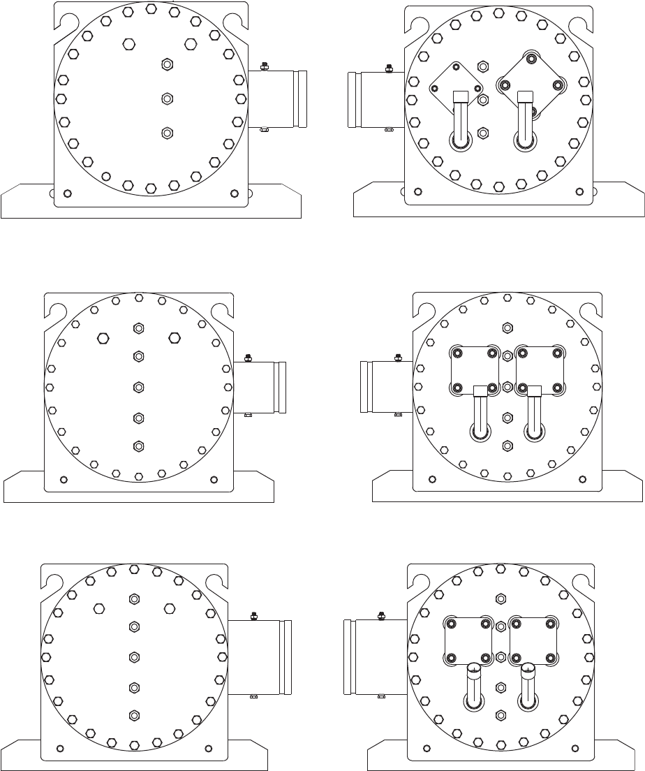
58
4
8
12
16
20
24
23
19
15
11
5
7
27
9
13
17
21
25
26
22
18
14
10
6
2
3
1
4
8
12
16
20
24
23
19
15
11
5
7
27
9
13
17
21
25
26
22
18
14
10
6
2
3
1
Fig. 29 — Bolt Tightening Sequence, 30RB060,070
1
2
4
3
5
6
10
13
17
21
25
28
24
20
16
12
9
7
11
14
18
22
26
29
27
23
19
15
8
1
2
4
3
5
6
10
13
17
21
25
28
24
20
16
12
9
7
11
14
18
22
26
29
27
23
19
15
8
Fig. 30 — Bolt Tightening Sequence, 30RB080-100
1
2
4
3
5
10
13
17
21
25
28
24
20
16
12
9
7
11
14
18
22
26
29
27
23
19
15
8
6
1
2
4
3
5
10
13
17
21
25
28
24
20
16
12
9
7
11
14
18
22
26
29
27
23
19
15
8
6
Fig. 31 — Bolt Tightening Sequence, 30RB110-130

59
Totaline Environmentally Balanced Coil Cleaner Applica-
tion Equipment
•2
1
/
2
gallon garden sprayer
• water rinse with low velocity spray nozzle.
Totaline Environmentally Balanced Coil Cleaner Applica-
tion Instructions
1. Remove any foreign objects or debris attached to the coil
face or trapped within the mounting frame or brackets.
2. Put on personal protective equipment including safety
glasses and/or face shield, waterproof clothing and
gloves. It is recommended to use full coverage clothing.
3. Remove all surface loaded fibers and dirt with a vacuum
cleaner as described above.
4. Thoroughly wet finned surfaces with clean water and a
low velocity garden hose, being careful not to bend fins.
5. Mix Totaline environmentally balanced coil cleaner in a
2
1
/
2
gallon garden sprayer according to the instructions
included with the cleaner. The optimum solution tem-
perature is 100 F.
NOTE: Do NOT USE water in excess of 130 F, as the enzy-
matic activity will be destroyed.
6. Thoroughly apply Totaline environmentally balanced
coil cleaner solution to all coil surfaces including finned
area, tube sheets and coil headers.
7. Hold garden sprayer nozzle close to finned areas and
apply cleaner with a vertical, up-and-down motion. Avoid
spraying in horizontal pattern to minimize potential for
fin damage.
8. Ensure cleaner thoroughly penetrates deep into finned
areas.
9. Interior and exterior finned areas must be thoroughly
cleaned.
10. Finned surfaces should remain wet with cleaning solution
for 10 minutes.
11. Ensure surfaces are not allowed to dry before rinsing.
Reapplying cleaner as needed to ensure 10-minute satura-
tion is achieved.
12. Thoroughly rinse all surfaces with low velocity clean
water using downward rinsing motion of water spray
nozzle. Protect fins from damage from the spray nozzle.
1
2
4
3
5
11
15
19
30
26
22
18
14
10
12
8
7
16
20
24
28
31
29
25
21
17
13
9
6
27
23
1
2
4
3
5
11
15
19
30
26
22
18
14
10
12
8
7
16
20
24
28
31
29
25
21
17
13
9
6
27
23
Fig. 32 — Bolt Tightening Sequence, 30RB150-190, 315A/B, 345A/B, 360A/B, 390A/B
1
2
4
3
5
11
30
26
22
18
14
10
12
8
7
16
20
24
28
37
29
25
21
17
13
6
35
32
9
33
40
38
34
36
39
31
27
23
19
15
1
2
4
3
5
11
30
26
22
18
14
10
12
8
7
16
20
24
28
37
29
25
21
17
13
6
35
32
9
33
40
38
34
36
39
31
27
23
19
15
Fig. 33 — Bolt Tightening Sequence, 30RB210-300
CAUTION
Harsh chemicals, household bleach or acid or basic clean-
ers should not be used to clean outdoor or indoor coils of
any kind. These cleaners can be very difficult to rinse out
of the coil and can accelerate corrosion at the fin/tube inter-
face where dissimilar materials are in contact. If there is
dirt below the surface of the coil, use the Totaline
®
envi-
ronmentally balanced coil cleaner as described on page 57.
CAUTION
High velocity water from a pressure washer, garden hose,
or compressed air should never be used to clean a coil. The
force of the water or air jet will bend the fin edges and
increase airside pressure drop. Reduced unit performance
or nuisance unit shutdown may occur.

60
MCHX (Microchannel Heat Exchanger) Con-
denser Coil Maintenance and Cleaning Rec-
ommendations — Routine cleaning of coil surfaces is
essential to maintain proper operation of the unit. Elimination
of contamination and removal of harmful residues will greatly
increase the life of the coil and extend the life of the unit. The
following steps should be taken to clean MCHX condenser
coils:
1. Remove any foreign objects or debris attached to the coil
face or trapped within the mounting frame and brackets.
2. Put on personal protective equipment including safety
glasses and/or face shield, waterproof clothing and
gloves. It is recommended to use full coverage clothing.
3. Start high pressure water sprayer and purge any soap or
industrial cleaners from sprayer before cleaning condens-
er coils. Only clean potable water is authorized for clean-
ing condenser coils.
4. Clean condenser face by spraying the coil steady and uni-
formly from top to bottom while directing the spray
straight toward the coil. Do not exceed 900 psig or
30 degree angle. The nozzle must be at least 12 in. from
the coil face. Reduce pressure and use caution to prevent
damage to air centers.
As part of normal maintenance, check the coil for leaks and
corrosion. The condenser coil is connected to the refrigerant
circuit with a fitting that forms a dielectric coupling. The cou-
pling is held in place with two nuts and studs. The nuts should
be tightened to 10 lb-ft (13.6 N-m).
Condenser Fans — A formed metal mount bolted to the
fan deck supports each fan and motor assembly. A shroud and a
wire guard provide protection from the rotating fan. The ex-
posed end of fan motor shaft is protected from weather by
grease. If fan motor must be removed for service or replace-
ment, be sure to regrease fan shaft and reinstall fan guard. The
fan motor has a step in the motor shaft. For proper perfor-
mance, fan should be positioned such that it is securely seated
on this step. Tighten the bolt to 12 to 15 ft-lb (16 to 20 N-m).
Refrigerant Circuit
LEAK TESTING — Units are shipped with complete operat-
ing charge of refrigerant R-410A (see Physical Data tables
supplied in the 30RB Installation Instructions) and should be
under sufficient pressure to conduct a leak test. If there is no
pressure in the system, introduce enough nitrogen to search for
the leak. Repair the leak using good refrigeration practices.
After leaks are repaired, system must be evacuated and
dehydrated.
REFRIGERANT CHARGE — Refer to Physical Data tables
supplied in the 30RB Installation Instructions). Immediately
ahead of filter drier in each circuit is a factory-installed liquid
line service valve. Each filter drier has a
1
/
4
-in. Schrader con-
nection for charging liquid refrigerant.
Charging with Unit Off and Evacuated — Close liquid line
service valve before charging. Weigh in charge shown on unit
nameplate. Open liquid line service valve; start unit and allow
it to run several minutes fully loaded. Check for a clear sight
glass. Be sure clear condition is liquid and not vapor.
Charging with Unit Running — If charge is to be added while
unit is operating, all condenser fans and compressors must be
operating. It may be necessary to block condenser coils at low
ambient temperatures to raise condensing pressure to approxi-
mately 450 psig (3102 kPa) to turn all condenser fans on. Do
not totally block a coil to do this. Partially block all coils in
uniform pattern. Charge each circuit until sight glass shows
clear liquid, and has a liquid line temperature of 103 F (39 C) .
If unit has the HEVCF option, run unit in Service Test with all
compressors on. Fans will adjust high side pressure to the cor-
rect value, 125 F SCT (saturated condensing temperature),
450 psig.
Safety Devices — Chillers contain many safety devices
and protection logic built into electronic control. Following is a
brief summary of major safeties.
COMPRESSOR PROTECTION
Circuit Breaker — Each compressor is equipped with one
molded case circuit breaker to provide short circuit protection.
Do not bypass or increase size of a breaker to correct problems.
Determine cause for trouble and correct before resetting break-
er. Circuit breaker current rating is listed on individual circuit
breakers.
A high-pressure switch with a trip pressure of 641 psig
(4419 kPa) is mounted on the discharge line of each circuit.
Switch is wired in series with the SPM modules of all compres-
sors in the circuit. If switch opens, the SPM opens all compres-
sor contactors in the circuit and all compressors are locked off.
See the table below for high pressure switch protection.
CRANKCASE HEATERS — Each compressor has a 56-w
crankcase heater to prevent absorption of liquid refrigerant by
oil in crankcase when compressor is not running. Heater power
source is control power transformer.
Relief Devices — Fusible plugs are located in each
circuit to protect against damage from excessive pressures.
HIGH-SIDE PROTECTION — One device is located be-
tween condenser and filter drier; a second is on filter drier.
These are both designed to relieve pressure on a tempera-
ture rise to approximately 210 F (99 C).
LOW-SIDE PROTECTION — A device is located on
suction line and is designed to relieve pressure on a tempera-
ture rise to approximately 170 F (77 C).
CAUTION
Do not apply any chemical cleaners to MCHX condenser
coils. These cleaners can accelerate corrosion and damage
the coil.
CAUTION
Excessive water pressure will fracture the braze between
air centers and refrigerant tubes.
IMPORTANT: Check for proper fan rotation (coun-
terclockwise viewed from above). If necessary, switch
any 2 power leads to reverse fan rotation.
IMPORTANT: When adjusting refrigerant charge,
circulate fluid through cooler continuously to prevent
freezing and possible damage to the cooler. Do not over-
charge, and never charge liquid into the low-pressure
side of system.
DEVICE CUT-OUT CUT-IN
High Pressure
Switch
641 ± 10 psi
(4420 ± 70 kPa)
493 ± 29 psi
(3400 ± 200 kPa)
IMPORTANT: Never open any switch or disconnect
that deenergizes crankcase heaters unless unit is being
serviced or is to be shut down for a prolonged period.
After a prolonged shutdown or service, energize
crankcase heaters for 24 hours before starting unit.

61
Some local building codes require that relieved gases be
removed. This connection will allow conformance to this
requirement.
Compressors
COMPRESSOR REPLACEMENT — To change out a
faulty compressor, refer to the compressor replacement proce-
dure included with the new compressor.
Compressor oil equalization line fittings use Roto-lok fit-
tings. If a leak is detected at these fittings, tighten fitting to 110
lb-ft (149 N-m). If leak persists, open system and inspect gas-
ket surface for foreign material or damage. If debris is found,
clean the surface and install a new gasket. If the gasket surface
is damaged, replace the compressor. Do not reuse gaskets.
OIL CHARGE — All units are factory charged with polyol
ester (POE) oil to
7
/
8
sight glass. Acceptable oil level for each
compressor is
3
/
4
to
7
/
8
full in the sight glass. Refer to installa-
tion instructions for oil quantity.
When additional oil or a complete charge is required it must
meet the following specifications:
• Manufacturer . . . . . . . . . . . . . . . . ICI Emkarate RL 32H
• Oil Type . . . . . . . . . . . . . . . .Inhibited polyol ester-based
synthetic compressor lubricant.
• ISO Viscosity Grade . . . . . . . . . . . . . . . . . . . . . . . . . . 32
Do not reuse drained oil or any oil that has been exposed to
the atmosphere.
SYSTEM BURNOUT CLEANUP PROCEDURE — Some
compressor electrical failures can cause the motor to burn.
When this occurs, byproducts such as sludge, carbon, and
acids contaminate the system. There are 2 classifications of
motor burnouts, mild and severe. Test the oil for acidity using a
POE oil acid test kit to determine the severity of the burnout.
In a mild burnout, there is little or no detectable odor.
Compressor oil is clear or slightly discolored. An acid test of
the oil will be negative. This type of failure is treated the same
as a mechanical failure. The liquid line filter drier or core
should be replaced.
In a severe burnout, there is a strong, pungent, rotten egg
odor. Compressor oil is very dark. Evidence of burning may be
present in the tubing connected to the compressor. An acid test
of the oil will be positive. The following steps should be taken
before restarting any compressors in the circuit.
1. Isolate compressors and recover refrigerant from com-
pressor section.
2. Remove oil from all compressors in the circuit. An oil
drain fitting is provided on each compressor. Pressurize
the low side of the compressor circuit with nitrogen. Less
than 10 psig (68.9 kPa) should be adequate. This will help
in the removal of the oil from the compressor sump. Dis-
pose of contaminated oil as per local codes and
regulations.
3. Replace failed compressor as outlined under compressor
replacement procedure.
4. Recharge the circuit with fresh oil. The circuit oil charge
information is supplied in the 30RB Installation Instruc-
tions. Oil level should be approximately
7
/
8
sight glass.
5. Install activated carbon (burnout) filter drier/core.
6. Leak check, evacuate and recharge refrigerant circuit.
7. Operate compressors. Check filter drier pressure drop
periodically. Replace cores if pressure drop exceeds
4 psig (27.6 kPa).
Perform additional acid test after 24 hours of operation.
Change liquid line filter drier/core if necessary. Replace with
standard filter drier/core once circuit is clean. Use the Carrier
Standard Service Techniques Manual as a reference source.
MAINTENANCE
Recommended Maintenance Schedule —
The
following are only recommended guidelines. Jobsite conditions
may dictate that maintenance schedule is performed more often
than recommended.
Routine:
For machines with e-coat condenser coils:
• Periodic clean water rinse, especially in coastal and
industrial applications.
Every month:
• Check condenser coils for debris, clean as necessary fol-
lowing recommended guidelines.
• Check moisture indicating sight glass for possible refrig-
erant loss and presence of moisture.
Every 3 months (for all machines):
• Check refrigerant charge.
• Check all refrigerant joints and valves for refrigerant
leaks, repair as necessary.
• Check chilled water flow switch operation.
• Check condenser coils for debris, clean as necessary fol-
lowing recommended guidelines.
• Check sight glass moisture indicator for moisture.
• Check all condenser fans for proper operation.
• Check compressor oil level.
• Check crankcase heater operation.
• Inspect pump seal, if equipped with a hydronic pump
package.
Every 12 months (for all machines):
• Check all electrical connections, tighten as necessary.
• Inspect all contactors and relays, replace as necessary.
• Check accuracy of thermistors, replace if greater than
±2° F (1.2° C) variance from calibrated thermometer.
• Check accuracy of transducers, replace if greater than
±5 psi (34.47 kPa) variance.
• Check to be sure that the proper concentration of anti-
freeze is present in the chilled water loop, if applicable.
• Verify that the chilled water loop is properly treated.
WARNING
Do not supply power to unit with compressor cover
removed. Failure to follow this warning can cause a fire
resulting in personal injury or death.
WARNING
Exercise extreme caution when reading compressor cur-
rents when high-voltage power is on. Correct any of the
problems described below before installing and running a
replacement compressor. Wear safety glasses and gloves
when handling refrigerants. Failure to follow this warning
can cause a fire, resulting personal injury or death.
CAUTION
Do not manually operate contactors. Serious damage to the
machine may result.
CAUTION
The compressor in a Puron
®
system uses a polyol ester
(POE) oil. This oil is extremely hygroscopic, meaning it
absorbs water readily. POE oils can absorb 15 times as
much water as other oils designed for HCFC and CFC
refrigerants. Take all necessary precautions to avoid expo-
sure of the oil to the atmosphere.

62
• Check refrigerant filter driers for excessive pressure
drop, replace as necessary.
• Check chilled water strainers, clean as necessary.
• Check cooler heater operation, if equipped.
• Check pump heater operation, if equipped.
• Check condition of condenser fan blades and that they
are securely fastened to the motor shaft.
• Perform Service Test to confirm operation of all
components.
Check for excessive cooler approach (Leaving Chilled
Water Temperature – Saturated Suction Temperature) which
may indicate fouling. Clean cooler vessel if necessary.
TROUBLESHOOTING
See Table 45 for an abbreviated list of symptoms, possible
causes and possible remedies.
Alarms and Alerts — The integral control system con-
stantly monitors the unit and generates warnings when abnor-
mal or fault conditions occur. Alarms may cause either a circuit
(Alert) or the whole machine (Alarm) to shutdown. Alarms and
Alerts are assigned codes as described in Fig. 34. The alarm/
alert indicator LED on the scrolling marquee or Navigator™
module is illuminated when any alarm or alert condition is
present. If an Alert is active, the Alarm Indicator LED will
blink. If an Alarm is active, the Alarm Indicator LED will
remain on. Currently active Alerts and Alarms can be found in
AlarmsALRMALM1 to ALM5.
The controller generates two types of alarms. Automatic
reset alarms will reset without any intervention if the condition
that caused the alarm corrects itself. Manual reset alarms
require the service technician to check for the alarm cause and
reset the alarm. The following method must be followed to
reset manual alarms:
Before resetting any alarm, first determine the cause of the
alarm and correct it. Enter the Alarms mode indicated by the
LED on the side of the scrolling marquee display. Press
and sub-mode AlarmR.ALM (Reset All Current
Alarms) is displayed. Press . The control will prompt
the user for a password, by displaying PASS and WORD. Press
to display 1111. Press for each character.
The default password is 0111. Use the arrow keys to change
each individual character. Use the up or down arrow keys to
toggle the display to YES and press . The alarms will
be reset. Indicator light will be turned off when switched
correctly. Do not reset the chiller at random without first inves-
tigating and correcting the cause(s) of the failure.
Each alarm is described by a three or four-digit code. The
first one or two digits indicate the alarm source and are listed
below. The last two digits pinpoint the problem. See Tables 46
and 47.
Table 45 — Troubleshooting
ENTER
ENTER
ENTER ENTER
ENTER
SYMPTOM POSSIBLE CAUSE POSSIBLE REMEDY
Unit Does Not Run Check for power to unit • Check overcurrent protection device.
• Check non-fused disconnect (if equipped).
• Restore power to unit.
Low refrigerant charge Check for leak and add refrigerant.
Wrong or incorrect unit configuration Check unit configuration.
Active alarm Check Alarm status. See separate Alarm and follow troubleshooting
instructions.
Active operating mode Check for Operating Modes. See Operating Modes and follow trouble-
shooting instructions. Check capacity control overrides.
Unit Operates too Long or
Continuously
Low refrigerant charge Check for leak and add refrigerant.
Compressor or control contacts welded Replace contactor or relay.
Air in chilled water loop Purge water loop.
Non-condensables in refrigerant circuit. Remove refrigerant and recharge.
Inoperative EXV • Check EXV, clean or replace.
• Check EXV cable, replace if necessary.
• Check EXV board for output signal.
Circuit Does Not Run Active alarm Check Alarm status. See separate Alarm and follow troubleshooting
instructions.
Active operating mode Check for Operating Modes. See Operating Modes and follow trouble-
shooting instructions.
Circuit Does Not Load Active alarm Check Alarm status. See separate Alarm and follow troubleshooting
instructions.
Active operating mode Check for Operating Modes. See Operating Modes and follow trouble-
shooting instructions.
Low saturated suction temperature See Operating Modes 21, 22 and 23.
High circuit suction superheat The circuit capacity is not allowed increase if circuit superheat is greater
than 36 F (20 C). See Alarms P.08, P.09 and P.10 for potential causes.
Low suction superheat The circuit capacity is not allowed to increase if the circuit superheat is
less than 5 F (2.8 C). See Alarms P.11, P.12 and P.13 for potential causes.
Compressor Does Not Run Active alarm Check Alarm status. See separate Alarm and follow troubleshooting
instructions.
Active operating mode Check for Operating Modes. See Operating Modes and follow trouble-
shooting instructions.
Inoperative compressor contactor • Check control wiring.
• Check scroll protection module.
• Check contactor operation, replace if necessary.
Chilled Water Pump is ON,
but the Machine is OFF
Cooler freeze protection Chilled water loop temperature too low. Check cooler heater.

63
Table 46 — Alarm Codes
LEGEND
PREFIX
CODE
SUFFIX
CODE
DESCRIPTION REASON FOR ALARM
ACTION TAKEN
BY CONTROL
RESET
TYPE
PROBABLE CAUSE
A1
A2
A3
A4
B1
B2
B3
B4
C1
C2
C3
C4
.01
Compressor nn Motor
Temperature Too High
Compressor Motor
Sensor PTC resistance
is greater than 4.5k
Circuit shut down
or not allowed to
start
Manual
Compressor failure,
wiring error, operation
outside of limits, improper
refrigerant charge
.02
Compressor nn Crankcase
Heater Failure
Crankcase heater
current not detected
when required or
detected when not
required.
Compressor shut
down or not
allowed to start
Manual
Wiring error, failed
crankcase heater,
failed SPM.
.03
Compressor nn High Pressure
Switch
High Pressure Switch
open.
Circuit shut down
or not allowed to
start
Manual
Wiring error, closed/
restricted discharge
valve, improper
refrigerant charge,
dirty condenser coils,
failed outdoor fan motor,
discharge pressure
transducer inaccuracy
.04
Compressor nn Motor Sensor
PTC Out of Range
Compressor Motor
Sensor PTC resistance
is less than 50 or
greater than 17k .
Circuit shut down
or not allowed to
start
Manual
Wiring error, operation
outside of limits, com-
pressor failure, improper
refrigerant charge
.05 Compressor nn Power Reset
24-VAC power lost to
SPM board.
Compressor shut
down or not
allowed to start
Automatic
Low voltage from main
power supply.
.06
Compressor nn Low Control
Voltage Alert
24-VAC power to SPM
board too low.
Compressor shut
down or not
allowed to start
Automatic
Low voltage from main
power supply.
EMM — Energy Management Module OAT — Outdoor Air Temperature
EWT — Entering Water Temperature PTC — Positive Temperature Coefficient
EXV — Electronic Expansion Valve SCT — Saturated Condensing Temperature
HR — Heat Reclaim SPM — Scroll Protection Module
LWT — Leaving Water Temperature SST — Saturated Suction Temperature
MOP — Maximum Operating Pressure

64
Table 46 — Alarm Codes (cont)
LEGEND
PREFIX
CODE
SUFFIX
CODE
DESCRIPTION REASON FOR ALARM
ACTION TAKEN
BY CONTROL
RESET
TYPE
PROBABLE CAUSE
Co
.A1
Loss of Communication with
Compressor Board A1
No communication with
SPM
Affected com-
pressor is
shut down
Automatic
Wrong SPM address,
wrong unit configuration,
wiring error, power loss to
SPM.
.A2
Loss of Communication with
Compressor Board A2
.A3
Loss of Communication with
Compressor Board A3
.A4
Loss of Communication with
Compressor Board A4
.B1
Loss of Communication with
Compressor Board B1
.B2
Loss of Communication with
Compressor Board B2
.B3
Loss of Communication with
Compressor Board B3
.B4
Loss of Communication with
Compressor Board B4
.C1
Loss of Communication with
Compressor Board C1
.C2
Loss of Communication with
Compressor Board C2
.C3
Loss of Communication with
Compressor Board C3
.C4
Loss of Communication with
Compressor Board C4
.E1
Loss of Communication with
EXV Board Number 1
No communication with
EXV1
Circuit A & B shut
down or not
allowed to start
Automatic
Wrong module address,
wrong unit configuration,
wiring error, power loss to
module
.E2
Loss of Communication with
EXV Board Number 2
No communication with
EXV2
Circuit C shut
down or not
allowed to start
.F1
Loss of Communication with
Fan Board Number 1
No communication with
Fan Board 1
Circuit A & B shut
down or not
allowed to start
(060-150,
210-250)
Circuit A shut
down or not
allowed to start
(160-190,
275-300)
Automatic
Wrong module address,
wrong unit configuration,
wiring error, power loss to
module
.F2
Loss of Communication with
Fan Board Number 2
No communication with
Fan Board 2
Circuit B shut
down or not
allowed to start
(160-190,
275-300)
.F3
Loss of Communication with
Fan Board Number 3
No communication with
Fan Board 3
Circuit C shut
down or not
allowed to start
(210-300)
.O1
Loss of Communication with
Free Cooling Board
No communication with
Free Cooling Board
None Automatic Configuration error.
.O2
Loss of Communication with
Electrical Heaters Board
No communication with
Electrical Heaters Board
.O3
Loss of Communication with
Energy Management Board
No communication with
Energy Management
Board
Disable or not
allow EMM
Functions
(3-Step and
4-20 mA Demand
Limit, 4-20 mA
and Space
Temperature
Reset, Occu-
pancy Override,
and Ice Build)
Automatic
Wrong module address,
wrong unit configuration,
wiring error, power loss to
module
.O4
Loss of Communication with
Heat Reclaim Board
No communication with
Heat Reclaim Board
Unit shall return
to the standard air
cooled mode
Automatic
Wrong module address,
wrong unit configuration,
wiring error, power loss to
module
EMM — Energy Management Module OAT — Outdoor Air Temperature
EWT — Entering Water Temperature PTC — Positive Temperature Coefficient
EXV — Electronic Expansion Valve SCT — Saturated Condensing Temperature
HR — Heat Reclaim SPM — Scroll Protection Module
LWT — Leaving Water Temperature SST — Saturated Suction Temperature
MOP — Maximum Operating Pressure

65
Table 46 — Alarm Codes (cont)
LEGEND
PREFIX
CODE
SUFFIX
CODE
DESCRIPTION REASON FOR ALARM
ACTION TAKEN
BY CONTROL
RESET
TYPE
PROBABLE CAUSE
Ct
.01
Circuit A Welded Contactor
Failure
Controls determine com-
pressor is still running
when circuit should be off
EXV, fan control,
and pump oper-
ate as normal to
save compressor
until high pres-
sure, freeze, or
flow failure condi-
tions occur
Manual
One or more circuit com-
pressor contactors
welded closed.
.02
Circuit B Welded Contactor
Failure
Controls determine com-
pressor is still running
when circuit should be off
EXV, fan control,
and pump oper-
ate as normal to
save compressor
until high pres-
sure, freeze, or
flow failure condi-
tions occur
Manual
One or more circuit com-
pressor contactors
welded closed.
.03
Circuit C Welded Contactor
Failure
Controls determine com-
pressor is still running
when circuit should be off
EXV, fan control,
and pump oper-
ate as normal to
save compressor
until high pres-
sure, freeze, or
flow failure condi-
tions occur
Manual
One or more circuit com-
pressor contactors
welded closed.
FC
.n0
Initial Factory Configuration
Required
No configuration
Unit not allowed
to start
Automatic
Configuration error. Pass-
word may default to
0113.
.nn Illegal Configuration
Wrong or incompatible
configuration data
Unit not allowed
to start
Automatic Configuration error.
MC .nn
Master Chiller Configuration
Error
Wrong or incompatible
configuration data
Unit not allowed
to start in Master-
Slave Control
Automatic
Configuration error. Refer
to Table 49.
P
.01
Water Exchanger Freeze
Protection
Entering or Leaving
Thermistor sensed a
temperature at or below
freeze point.
Unit shut down or
not allowed to
start. Chilled
Water Pump will
be started
Automatic, first
occurrence in
24 hours,
Manual, if
multiple
alarms within
24 hours
Faulty thermistor, faulty
wiring, low water flow
rate, low loop volume, or
freeze conditions.
.05
Circuit A Low Suction
Temperature
Low Saturated Suction
Temperatures sensed for
a period of time.
Circuit shut down
Automatic, first
occurrence in
24 hours,
Manual, if
multiple
alarms within
24 hours
Faulty transducer, faulty
wiring, low water flow
rate, low loop volume,
fouled cooler, or freeze
conditions.
.06
Circuit B Low Suction
Temperature
.07
Circuit C Low Suction
Temperature
.08 Circuit A High Superheat
EXV>98%, Suction
Superheat >54 F (30.0 C)
and SST<MOP for more
than 5 minutes
Circuit shut down Manual
Faulty transducer, faulty
thermistor, faulty wiring,
faulty EXV, low refriger-
ant charge, plugged or
restricted liquid line.
.09 Circuit B High Superheat
.10 Circuit C High Superheat
.11 Circuit A Low Superheat
EXV 5% and Suction
Superheat is less than
the superheat setting by
at least 5 F (2.8 C) or
SST>Maximum Operat-
ing Pressure for more
than 5 minutes
Circuit shut down
Automatic, first
occurrence in
24 hours,
Manual, if
multiple
alarms within
24 hours
Faulty transducer, faulty
thermistor, faulty wiring,
faulty EXV, or incorrect
configuration.
.12 Circuit B Low Superheat
.13 Circuit C Low Superheat
.14 Cooler Interlock Failure
Cooler Pump Interlock
circuit opens (consists of
chilled water flow system
and chilled water pump
interlock)
Unit shut down or
not allowed to
start
Automatic if
stage=0,
Manual if
stage>0.
Low Water Flow, faulty
wiring or contacts, faulty
water flow switch, or
chilled water pump
problem. Remote lockout
if unit is equipped with an
EMM.
EMM — Energy Management Module OAT — Outdoor Air Temperature
EWT — Entering Water Temperature PTC — Positive Temperature Coefficient
EXV — Electronic Expansion Valve SCT — Saturated Condensing Temperature
HR — Heat Reclaim SPM — Scroll Protection Module
LWT — Leaving Water Temperature SST — Saturated Suction Temperature
MOP — Maximum Operating Pressure

66
Table 46 — Alarm Codes (cont)
LEGEND
PREFIX
CODE
SUFFIX
CODE
DESCRIPTION REASON FOR ALARM
ACTION TAKEN
BY CONTROL
RESET
TYPE
PROBABLE CAUSE
P
.15 Condenser Flow Switch Failure — None Manual Configuration error.
.16
Compressor A1 Not Started or
Pressure not Established
Compressor differential
(Discharge-Suction) did
not increase by 10 psig
(69 kPa) in 2 minutes
Circuit shut down Manual
No power to the com-
pressor, faulty compres-
sor contactor, low control
voltage, faulty discharge
or suction pressure
transducers, wiring
error, improper electrical
phasing.
.17
Compressor A2 Not Started or
Pressure not Established
.18
Compressor A3 Not Started or
Pressure not Established
.19
Compressor A4 Not Started or
Pressure not Established
.20
Compressor B1 Not Started or
Pressure not Established
.21
Compressor B2 Not Started or
Pressure not Established
.22
Compressor B3 Not Started or
Pressure not Established
.23
Compressor B4 Not Started or
Pressure not Established
.24
Compressor C1 Not Started or
Pressure not Established
.25
Compressor C2 Not Started or
Pressure not Established
.26
Compressor C3 Not Started or
Pressure not Established
.27
Compressor C4 Not Started or
Pressure not Established
.28
Electrical Box Thermostat
Failure
Improper phasing
detected by the reverse
rotation board
Unit not allowed
to start
Automatic
Check power phasing,
improper wiring, or faulty
detection board.
.29
Loss of Communication with
System Manager
Loss of communication
with an external control
device for more than
2 minutes
Unit changes to
stand alone
operation
Automatic
Faulty communication
wiring, no power supply
to the external controller.
.30
Master/Slave Communication
Failure
Communication between
the master and slave
machines has been lost.
Units operate as
stand alone
machines
Automatic
Faulty communication
wiring, no power or con-
trol power to the main
base board to either
module.
.31 Unit is in Emergency Stop
Emergency Stop com-
mand has been received.
Unit shuts down
or not allowed to
start.
Automatic
Carrier Comfort Net-
work
®
Emergency Stop
Command received.
.32 Cooler Pump 1 Fault
Pump Interlock status
does not match pump
status.
Unit shuts down.
If available,
another pump will
start.
Manual
Faulty contacts, wiring
error, or low control
voltage.
.33 Cooler Pump 2 Fault
.34
Circuit A Reclaim Operation
Failure
Circuit A Reclaim Opera-
tion Failure
Reclaim operation
failure due to high
SCT
The affected
circuit shall
return to air
cooled mode
Manual
.35
Circuit B Reclaim Operation
Failure
Circuit B Reclaim Opera-
tion Failure
.37
Circuit A Repeated High
Discharge Gas Overrides
Multiple capacity
overrides due to high
saturated discharge
temperatures
Circuit shut down Automatic
Condenser air recircula-
tion, dirty or plugged con-
denser coils, inaccurate
discharge transducer,
faulty condenser fan,
.38
Circuit B Repeated High
Discharge Gas Overrides
.39
Circuit C Repeated High
Discharge Gas Overrides
.40
Circuit A Repeated Low
Suction Temperature Overrides
Multiple capacity over-
rides due to low saturated
suction temperatures
Circuit shut down Manual
Low water flow, low loop
volume, fouled cooler,
low refrigerant charge,
unit not configured for
brine with glycol in cooler.
.41
Circuit B Repeated Low
Suction Temperature Overrides
.42
Circuit C Repeated Low
Suction Temperature Overrides
.97
Water Exchanger Temperature
Sensors Swapped
Control detects EWT
below LWT for 1 minute
Unit shuts down Manual Wiring error. EWT and
LWT sensors swapped.
EMM — Energy Management Module OAT — Outdoor Air Temperature
EWT — Entering Water Temperature PTC — Positive Temperature Coefficient
EXV — Electronic Expansion Valve SCT — Saturated Condensing Temperature
HR — Heat Reclaim SPM — Scroll Protection Module
LWT — Leaving Water Temperature SST — Saturated Suction Temperature
MOP — Maximum Operating Pressure

67
Table 46 — Alarm Codes (cont)
LEGEND
PREFIX
CODE
SUFFIX
CODE
DESCRIPTION REASON FOR ALARM
ACTION TAKEN
BY CONTROL
RESET
TYPE
PROBABLE CAUSE
Pr
.01 Circuit A Discharge Transducer
Measured voltage is
0 vdc
Circuit shut down
or not allowed to
start.
Automatic
Faulty transducer, wiring
error, failed Main Base
Board or Fan Board 3.
Compressor circuit
breaker tripped.
.02 Circuit B Discharge Transducer
.03 Circuit C Discharge Transducer
.04 Circuit A Suction Transducer
.05 Circuit B Suction Transducer
.06 Circuit C Suction Transducer
.07
Circuit A Reclaim Pumpdown
Pressure Transducer
The affected cir-
cuit shall return to
air cooled mode
Automatic
Faulty transducer, wiring
error, failed EMM HR
board.
.08
Circuit B Reclaim Pumpdown
Pressure Transducer
Sr .nn Service Maintenance Alert
Field programmed
elapsed time has expired
for maintenance item
None Manual
Maintenance required
(see Table 50).
th
.01
Water Exchanger Entering
Fluid Thermistor Failure
Temperature measured
by the controller is less
than -40 F (-40 C) or
greater than 240 F
(115.6 C)
Unit will be shut
down or not
allowed to start.
Automatic
Faulty thermistor, wiring
error, failed Main Base
Board.
.02
Water Exchanger Leaving Fluid
Thermistor Failure
.03
Circuit A Defrost Thermistor
Failure
None Automatic Configuration error.
.04
Circuit B Defrost Thermistor
Failure
.08
Reclaim Condenser Entering
Thermistor
Unit shall return
to the standard air
cooled mode.
Automatic
Faulty thermistor, wiring
error, failed EMM HR
board.
.09
Reclaim Condenser Leaving
Thermistor
None
.10 OAT Thermistor Failure
Unit is shut down
or not allowed to
start. Cooler/
Pump heaters are
energized
Automatic
Faulty thermistor, wiring
error, failed Main Base
Board.
.11
Master/Slave Common Fluid
Thermistor
Dual Chiller deac-
tivated. Master
and Slave
machines oper-
ate in stand alone
mode
.12
Circuit A Suction Gas
Thermistor
Temperature measured
by the controller is less
than -40 F (-40 C) or
greater than 240 F
(115.6 C)
Circuit shut down
Automatic
Faulty thermistor, wiring
error, failed Main Base
Board or EXV Board
.13
Circuit B Suction Gas
Thermistor
Circuit shut down
.14
Circuit C Suction Gas
Thermistor
Circuit shut down
.18
Circuit A Condenser Subcool-
ing Liquid Thermistor
Unit shall return
to the standard air
cooled mode.
Automatic
Faulty thermistor, wiring
error, failed EMM HR
board.
.19
Circuit B Condenser Subcool-
ing Liquid Thermistor
.21
Space Temperature Sensor
Failure
Temperature
Reset based on
Space Tempera-
ture disabled
Faulty thermistor, wiring
error, failed Main Base
Board.
V0 xx
Circuit A Variable Speed Fan
Motor Failure
See Table 47 — Variable
Speed Fan Motor Alarm
Details on page 68
Danfoss drive only.
Alert—No action
Alarm—Circuit is
stopped
Automatic
See Table 47 — Variable
Speed Fan Motor Alarm
Details on page 68.
V1 xx
Circuit B Variable Speed Fan
Motor Failure
V2 xx
Circuit C Variable Speed Fan
Motor Failure
EMM — Energy Management Module OAT — Outdoor Air Temperature
EWT — Entering Water Temperature PTC — Positive Temperature Coefficient
EXV — Electronic Expansion Valve SCT — Saturated Condensing Temperature
HR — Heat Reclaim SPM — Scroll Protection Module
LWT — Leaving Water Temperature SST — Saturated Suction Temperature
MOP — Maximum Operating Pressure

68
Table 47 — Variable Speed Fan Motor Alarm Details, Danfoss Drive
NOTES:
1. (X) = Dependent on parameter
2. Trip lock condition is an alarm for a condition that could cause
damage to the drive. The alarm can only be reset by cycling
power to the drive.
3. If a warning and an alarm are marked against a code in the
table, this means that either a warning occurs before the alarm,
or it can be specified whether it is a warning or an alarm that is
to be displayed for a given fault.
4. Alarms are shown on the drive in parameters 16-90 through 16-
95. Parameters can only be accessed with drive display service
tool.
NO. DESCRIPTION WARNING
ALARM/
TRIP
ALARM/
TRIP LOCK
PARAMETER
REFERENCE
1 10 Volts low X
2 Live zero error (X) (X) 6-01
3 No motor (X) 1-80
4 Mains phase loss (X) (X) (X) 14-12
5 DC link voltage high X
6 DC link voltage low X
7 DC over voltage X X
8 DC under voltage X X
9 Inverter overloaded X X
10 Motor ETR overtemperature (X) (X) 1-90
11 Motor thermistor over temperature (X) (X) 1-90
12 Torque limit X X
13 Over current X X X
14 Earth fault X X X
15 Hardware mismatch X X
16 Short circuit X X
17 Control word timeout (X) (X) 8-04
18 Start failed X
23 Internal fan fault X
24 External fan fault X 14-53
25 Barke resistor short-circuited X
26 Brake resistor power limit (X) (X) 2-13
27 Brake chopper short-circuited X X
28 Brake check (X) (X) 2-15
29 Drive over temperature X X X
30 Motor phase U missing (X) (X) (X) 4-58
31 Motor phase V missing (X) (X) (X) 4-58
32 Motor phase W missing (X) (X) (X) 4-58
33 Inrush fault X X
34 Field bus communication fault X X
35 Out of frequency range X X
36 Mains failure X X
37 Phase imbalance X X
38 Internal fault X X
39 Heatsink sensor X X
40 Overload of Digital Output Terminal 27 (X) 5-00, 5-01
41 Overload of Digital Output Terminal 29 (X) 5-00, 5-02
42 Overload of Digital Output Terminal On X30/6 (X) 5-32
42 Overload of Digital Output Terminal On X30/7 (X) 5-33
46 Power card supply X X
47 24 V supply low X X X
48 1.8 V supply low X X
49 Speed limit X (X) 1-86
50 AMA calibration failed X
51 AMA check U
nom
and I
nom
X
52 AMA low I
nom
X
53 AMA motor too big X
54 AMA motor too small X
55 AMA parameter out of range X
56 AMA interrupted by user X
57 AMA timeout X
58 AMA internal fault X X
59 Current limit X
60 External Interlock X

69
Table 47 — Variable Speed Fan Motor Alarm Details, Danfoss Drive (cont)
NOTES:
1. (X) = Dependent on parameter
2. Trip lock condition is an alarm for a condition that could cause
damage to the drive. The alarm can only be reset by cycling
power to the drive.
3. If a warning and an alarm are marked against a code in the
table, this means that either a warning occurs before the alarm,
or it can be specified whether it is a warning or an alarm that is
to be displayed for a given fault.
4. Alarms are shown on the drive in parameters 16-90 through 16-
95. Parameters can only be accessed with drive display service
tool.
NO. DESCRIPTION WARNING
ALARM/
TRIP
ALARM/
TRIP LOCK
PARAMETER
REFERENCE
62 Output frequency at maximum limit X
64 Voltage limit X
65 Control board over-temperature X X X
66 Heat sink temperature low X
67 Option configuration has changed X
69 Power card temperature X X
70 Illegal FC configuration X
71 PTC 1 Safe Stop X X
72 Dangerous failure X
73 Safe stop auto restart
76 Power unit setup X
79 Illegal PS configuration X X
80 Drive initialized to default value X
91 Analog input 54 wrong settings X
92 NoFlow X X 22-2
93 Dry pump X X 22-2
94 End of curve X X 22-5
95 Broken belt X X 22-6
96 Start delayed X 22-7
97 Stop delayed X 22-7
98 Clock fault X 0-7
201 Fire M was active
202 Fire M limits exceeded
203 Missing motor
204 Locked rotor
243 Brake IGBT X X
244 Heatsink temperature X X X
245 Heatsink sensor X X
246 Power card supply X X
247 Power card temperature X X
248 Illegal PS configuration X X

70
DIAGNOSTIC ALARM CODES AND POSSIBLE
CAUSES
Motor Temperature Too High
A1.01 — Compressor A1
A2.01 — Compressor A2
A3.01 — Compressor A3
A4.01 — Compressor A4
B1.01 — Compressor B1
B2.01 — Compressor B2
B3.01 — Compressor B3
B4.01 — Compressor B4
C1.01 — Compressor C1
C2.01 — Compressor C2
C3.01 — Compressor C3
C4.01 — Compressor C4
Criteria for Trip — The alarm criterion is checked whether the
compressor is ON or OFF. This alarm will be generated if the
scroll protection module (SPM) detects a compressor motor
PTC (positive temperature coefficient) resistance greater than
4500 ohms, indicating that the motor temperature is too high.
Action to be Taken — The circuit shuts down immediately or
is not allowed to start.
Reset Method — Manual. PTC resistance must be less than
2500 ohms
Possible Causes — If this condition is encountered, check the
following items:
• Check for a PTC thermistor failure.
• Check for a compressor motor failure.
• Check for a wiring error.
• Check wiring terminations for corrosion.
• Check for operation outside of the limits.
• Check for condenser air recirculation.
• Check the circuit for proper charge.
• Check the EXV for proper operation.
• Check the EXV input devices, pressure transducer and
temperature for accuracy.
• Check the liquid line filter drier for a restriction.
Crankcase Heater Failure
A1.02 — Compressor A1
A2.02 — Compressor A2
A3.02 — Compressor A3
A4.02 — Compressor A4
B1.02 — Compressor B1
B2.02 — Compressor B2
B3.02 — Compressor B3
B4.02 — Compressor B4
C1.02 — Compressor C1
C2.02 — Compressor C2
C3.02 — Compressor C3
C4.02 — Compressor C4
Criteria for Trip — The alarm criteria are checked whether the
compressor is ON or OFF. The scroll protection module
(SPM) monitors crankcase heater current draw. This family of
alarms is generated if one of the following criteria is detected:
1. The SPM fails to detect a crankcase current draw of at
least 0.5 amp while the crankcase heater is ON.
2. The SPM detects a crankcase current draw of at least
0.5 amp while the crankcase heater is OFF. The current is
sensed internally on the SPM.
Action to be Taken — If a fault is detected, the affected com-
pressor will be shut down or not allowed to start.
Reset Method — Manual
Possible Causes — If this condition is encountered, check the
following items:
• Check the wiring to the crankcase heater.
• Check the crankcase heater for operation.
• Check the SPM crankcase heater output operation.
• Confirm unit configuration.
High Pressure Switch
A1.03 — Compressor A1
A2.03 — Compressor A2
A3.03 — Compressor A3
A4.03 — Compressor A4
B1.03 — Compressor B1
B2.03 — Compressor B2
B3.03 — Compressor B3
B4.03 — Compressor B4
C1.03 — Compressor C1
C2.03 — Compressor C2
C3.03 — Compressor C3
C4.03 — Compressor C4
Criteria for Trip — The alarm criterion is checked whether the
circuit is ON or OFF. This alarm will be generated if the circuit
high-pressure switch (HPS) opens. The scroll protection mod-
ule (SPM) monitors the HPS. The 30RB units employ one
HPS for each circuit. The HPS signal is connected to all of the
SPM modules of the circuit.
Action to be Taken — The circuit shuts down immediately or
is not allowed to start.
Reset Method — Manual
Possible Causes — If this condition is encountered, check the
following items:
• Check the wiring of the high pressure switch circuit. Be sure
the HPS is connected to all of the SPM boards in the circuit.
• Check the maximum condensing temperature (MCT) for
the proper setting.
• Check for noncondensables in the refrigerant circuit.
• Check for condenser air re-circulation.
• Check for the proper refrigerant charge (overcharged).
• Check for operation beyond the limit of the machine.
• Check the condenser coils for debris or restriction.
• Check the condenser fans and motors for proper rotation
and operation.
• Check the discharge service valve to be sure that it is open.
A closed or restricted valve is a potential high pressure trip.
• Check the discharge pressure transducer for accuracy.
• Confirm unit configuration.
Alarm Descriptor
th
Alarm Suffix
Code Number to identify source
.01
Alarm Prefix
A1 – Compressor A1 Failure
A2 – Compressor A2 Failure
A3 – Compressor A3 Failure
A4 – Compressor A4 Failure
B1 – Compressor B1 Failure
B2 – Compressor B2 Failure
B3 – Compressor B3 Failure
B4 – Compressor B4 Failure
C1 – Compressor C1 Failure
C2 – Compressor C2 Failure
C3 – Compressor C3 Failure
C4 – Compressor C4 Failure
Co – Communication Failure
Ct – Circuit Welded Contactor Failure
FC – Factory Configuration Error
MC – Master Chiller Configuration Error
P – Process Failure
Pr – Pressure Transducer Failure
Sr – Service Notification
th – Thermistor Failure
V0 – Circuit A Variable Speed Fan Motor Failure
V1 – Circuit B Variable Speed Fan Motor Failure
V2 – Circuit C Variable Speed Fan Motor Failure
Alarm
Fig. 34 — Alarm Description

71
Motor Sensor PTC Out of Range
A1.04 — Compressor A1
A2.04 — Compressor A2
A3.04 — Compressor A3
A4.04 — Compressor A4
B1.04 — Compressor B1
B2.04 — Compressor B2
B3.04 — Compressor B3
B4.04 — Compressor B4
C1.04 — Compressor C1
C2.04 — Compressor C2
C3.04 — Compressor C3
C4.04 — Compressor C4
Criteria for Trip — The alarm criterion is checked whether the
circuit is ON or OFF. The scroll protection module (SPM)
monitors the compressor motor temperature. This alarm will
be generated if the motor sensor PTC in the compressor resis-
tance is less than 50 ohms or greater than 17,000 ohms.
Action to be Taken — The circuit shuts down immediately or
not allowed to start.
Reset Method — Manual
Possible Causes — If this condition is encountered, check the
following items:
• Check the sensor wiring to the scroll compressor protec-
tion module (SPM).
• Check for a faulty SPM.
• Check for a compressor failure.
• Check for noncondensables in the refrigerant circuit.
• Check for condenser air re-circulation.
• Check for the proper refrigerant charge (overcharged).
• Check for operation beyond the limit of the machine.
• Check the condenser coils for debris or restriction.
• Check the condenser fans and motors for proper rotation
and operation.
• Check the discharge service valve to be sure that it is open.
• Check the discharge pressure transducer for accuracy.
• Confirm unit configuration.
SPM Board Power Reset
A1.05 – Compressor A1
A2.05 – Compressor A2
A3.05 – Compressor A3
A4.05 – Compressor A4
B1.05 – Compressor B1
B2.05 – Compressor B2
B3.05 – Compressor B3
B4.05 – Compressor B4
C1.05 – Compressor C1
C2.05 – Compressor C2
C3.05 – Compressor C3
C4.05 – Compressor C4
Criteria for Trip — The alarm criterion is checked whether the
compressor is ON or OFF. The scroll protection module
(SPM) monitors the 24 vac at the compressor through the high
pressure switch input channel. This alarm will be generated if
the main base board receives a signal from the SPM board
indicating that the compressor went through a power cycle.
Action to be Taken — The compressor is shut down immedi-
ately or not allowed to start.
Reset Method — Automatic
Possible Causes — If this condition is encountered, check the
following items:
• Check the voltage from the main three phase power
supply
• Check the 24 vac wiring connections to the scroll com-
pressor protection module (SPM)
• Check for a faulty SPM.
SPM Board Low Control Voltage Alert
A1.06 – Compressor A1
A2.06 – Compressor A2
A3.06 – Compressor A3
A4.06 – Compressor A4
B1.06 – Compressor B1
B2.06 – Compressor B2
B3.06 – Compressor B3
B4.06 – Compressor B4
C1.06 – Compressor C1
C2.06 – Compressor C2
C3.06 – Compressor C3
C4.06 – Compressor C4
Criteria for Trip — The alarm criterion is checked whether the
compressor is ON or OFF. The scroll protection module
(SPM) monitors the 24 vac at the compressor through the high
pressure switch input channel. This alarm will be generated if
the main base board receives a signal from the SPM board
indicating that the 24 vac level was lower than the allowed
minimum threshold.
Action to be Taken — The compressor is shut down immedi-
ately or not allowed to start as to prevent any contactor chatter-
ing/welding from occurring.
Reset Method — Automatic
Possible Causes — If this condition is encountered, check the
following items:
• Check the voltage from the main three phase power
supply.
• Check the 24 vac wiring connections to the scroll com-
pressor protection module (SPM).
• Check for a faulty SPM.
Loss of Communication with Compressor
Co.A1 — Board A1
Co.A2 — Board A2
Co.A3 — Board A3
Co.A4 — Board A4
Co.B1 — Board B1
Co.B2 — Board B2
Co.B3 — Board B3
Co.B4 — Board B4
Co.C1 — Board C1
Co.C2 — Board C2
Co.C3 — Board C3
Co.C4 — Board C4
Criteria for Trip — The alarm criterion is tested whether the
unit is ON or OFF. If communication with the scroll compres-
sor protection module (SPM) is lost for a period of 10 seconds,
the alarm will be generated.
Action to be Taken — The affected compressor will be shut
down.
Reset Method — Automatic, if communication is established,
the compressor, if called for will start normally.
Possible Causes — If this condition is encountered, check the
following items:
• Check the power supply to the affected SPM.
• Check the address of the SPM to be sure that it is correct.
• Check the Local Equipment Network (LEN) wiring to be
sure that it is connected properly.
• Confirm unit configuration.
Co.E1— Loss of Communication with EXV Board Number 1
Criteria for Trip — The alarm criterion is tested whether the
unit is ON or OFF. If communication with EXV1 is lost for a
period of 10 seconds, the alarm will be triggered.
Action to be Taken — If running, Circuit A and B will shut
down normally. If Circuit A or Circuit B is not operating, it
will not be allowed to start.
Reset Method — Automatic, if communication is established,
the unit will start normally.

72
Possible Causes — If this condition is encountered, check the
following items:
• Check the power supply to EXV1.
• Check the address of the EXV1 to be sure that it is
correct.
• Check the Local Equipment Network (LEN) wiring to be
sure that it is connected properly.
• Confirm unit configuration.
Co.E2 — Loss of Communication with EXV Board Number 2
Criteria for Trip — The alarm criterion is tested whether the
unit is ON or OFF, on 30RB210-300 units only.
Action to be Taken — If communication with EXV Board 2 is
lost for a period of 10 seconds, the alarm will be triggered. If
running, Circuit C will shut down normally. If Circuit C is not
running, it will not be allowed to start.
Reset Method — Automatic, if communication is established,
the unit will start normally.
Possible Causes — If this condition is encountered, check the
following items:
• Check the power supply to EXV Board 2.
• Check the address of the EXV Board 2 to be sure that it
is correct.
• Check the Local Equipment Network (LEN) wiring to be
sure that it is connected properly.
• Confirm unit configuration.
Co.F1 — Loss of Communication with Fan Board Number 1
Criteria for Trip — The criterion is tested whether the unit is
ON or OFF. If communication with Fan Board 1 is lost for a
period of 10 seconds, the alarm will be triggered.
Action to be Taken — For 30RB060-150 and 30RB210-250,
Circuit A and B will shut down normally if they are running.
For 30RB160-190 and 30RB275-300, Circuit A will shut
down normally if it is running. If the circuit or circuits con-
trolled by the board are not running, then they will not be
allowed to start.
Reset Method — Automatic, if communication is established,
the unit will start normally.
Possible Causes — If this condition is encountered, check the
following items:
• Check the power supply to Fan Board 1.
• Check the address of the Fan Board 1 to be sure that it is
correct.
• Check the Local Equipment Network (LEN) wiring to be
sure that it is connected properly.
• Confirm unit configuration.
Co.F2 — Loss of Communication with Fan Board Number 2
Criteria for Trip — The criterion is tested whether the unit is
ON or OFF and on 30RB160-190, 275, and 300 only.
Action to be Taken — If communication with Fan Board 2 is
lost for a period of 10 seconds, the alarm will be triggered. If
running, Circuit B will shut down normally for 30RB160-190,
275 and 300. If Circuit B is not running for 30RB160-190, 275
and 300, then it will not be allowed to start.
Reset Method — Automatic, if communication is established,
the unit will start normally.
Possible Causes — If this condition is encountered, check the
following items:
• Check the power supply to Fan Board 2.
• Check the address of the Fan Board 2 to be sure that it is
correct.
• Check the Local Equipment Network (LEN) wiring to be
sure that it is connected properly.
• Confirm unit configuration.
Co.F3 — Loss of Communication with Fan Board Number 3
Criteria for Trip — The criterion is tested whether the unit is
ON or OFF, and on 30RB210-300 machines only. If
communication with Fan Board 3 is lost for a period of 10 sec-
onds, the alarm will be triggered.
Action to be Taken — If running, Circuit C will shut down nor-
mally for 30RB210-300. If the circuit is not running for
30RB210-300, then it will not be allowed to start.
Reset Method — Automatic, if communication is established,
the unit will start normally.
Possible Causes — If this condition is encountered, check the
following items:
• Check the power supply to Fan Board 3.
• Check the address of the Fan Board 3 to be sure that it is
correct.
• Check the Local Equipment Network (LEN) wiring to be
sure that it is connected properly.
• Confirm unit configuration.
Co.O1 — Loss of Communication with Free Cooling Board
Criteria for Trip — This alarm is for a free cooling machine
only. This feature is not supported for a cooling only machine.
Action to be Taken — None
Reset Method — Automatic
Possible Causes — If this condition is encountered, confirm
unit configuration.
Co.O2 — Loss of Communication with Electrical Heaters Board
Criteria for Trip — This alarm is for a heat pump machines
only. This feature is not supported for a cooling only machine.
Action to be Taken — None
Reset Method — Automatic
Possible Causes — If this condition is encountered, confirm
unit configuration.
Co.O3 — Loss of Communication with Energy Management
Board
Criteria for Trip — The criterion is tested whether the unit is
ON or OFF and when a function that requires the energy
management module (EMM) is configured. If communication
with the EMM is lost for a period of 10 seconds, the alarm will
be triggered.
Action to be Taken — If any function controlled by the EMM
(3-Step and 4-20 mA Demand Limit, 4-20 mA and Space
Temperature Reset, Occupancy Override, and Ice Build) is
active, that function will be terminated. If an EMM function is
programmed, and communication is lost, the function will not
be allowed to start.
Reset Method — Automatic, if communication is established,
the functions will be enabled.
Possible Causes — If this condition is encountered, check the
following items:
• Check configuration to see if the EMM is installed, (Con-
figurationUNITEMM). If (EMM=YES), check for
a control option that requires the EMM that may be
enabled. Correct configuration if not correct.
• Check the power supply to EMM.
• Check the address of the EMM to be sure that it is correct.
• Check the Local Equipment Network (LEN) wiring to be
sure that it is connected properly.
• Check unit configuration to be sure that no options that
require the EMM are enabled.
Co.O4 — Loss of Communication with Heat Reclaim Board
Criteria for Trip — This alarm is tested whether the unit is
ON or OFF and when the unit is configured for Heat Reclaim.
If communication with the heat reclaim board is lost for a
period of 10 seconds, the alarm will be triggered.
Action to be Taken — The unit will return to the air cooled
mode.
Reset Method — Automatic, when communication is estab-
lished, the functions will be enabled.

73
Possible Causes — If this condition is encountered, check the
following items:
• Check the power supply to heat reclaim board.
• Check the Local Equipment Network (LEN) wiring to be
sure that it is connected properly.
• Check unit configuration to be sure that Heat Reclaim is
enabled and unit does NOT contain the Heat Reclaim
option.
Welded Contactor Failure
Ct.01 – Circuit A
Ct.02 – Circuit B
Ct.03 – Circuit C
Criteria For Trip — This alarm is tested for when the circuit is
off (all compressors switched to off). The algorithm will evalu-
ate saturated suction and saturated condensing temperatures to
determine if the compressor is still running even though it has
been commanded off.
Action to be Taken
1. Unit capacity will go to and remain at 0%. The EXV, fan
control, and cooler pump will continue their normal
operation.
2. If a high pressure, cooler flow, or cooler freeze failure oc-
curs, then circuit operation is disabled. The critical alarm
relay will be energized in order to shut off the main power
supply.
Reset Method — Reset is manual.
FC.n0 — Initial Factory Configuration Required
Criteria for Trip — The criterion is tested whether the unit is
ON or OFF. The alarm will be generated if the Configuration
UNITTONS=0.
Action to be Taken — The unit is not allowed to start.
Reset Method — Automatic after factory configuration is com-
plete. The configuration must be manually completed. The
password may default to 0113.
Possible Causes — If this condition is encountered, confirm
the unit configuration.
FC.nn — Illegal Configuration
Criteria for Trip — The criterion is tested whether the unit is
ON or OFF. The alarm will be generated if the one of the fol-
lowing configuration errors is detected by the control. The
“nn” refers to the error code listed in Table 48.
Table 48 — Illegal Configuration Alarm Code
Action to be Taken — The unit is not allowed to start.
Reset Method — Automatic after factory reconfiguration is
completed. A power cycle may be required.
Possible Causes — If this condition is encountered, confirm
the unit configuration.
MC.nn — Master Chiller Configuration Error
Criteria for Trip — The criterion is tested whether the unit is
ON or OFF. The units must be configured as a Master and
Slave machine (ConfigurationRSETMSSL=1 and Con-
figurationRSETMSSL=2), and one of the following
configuration errors has been found. The “nn” refers to the
error code listed in Table 49.
Action to be Taken — Unit not allowed to start in Master Slave
control.
Reset Method — Automatic
Possible Causes — If this condition is encountered, confirm
proper configuration.
P.01 — Water Exchanger Freeze Protection
Criteria for Trip — The alarm criteria are checked whether the
unit is ON or OFF. If the entering or leaving water thermistor
senses a temperature at the freeze point or less, the alarm will
be generated. For a fresh water system (Configuration
SERVFLUD=1), the freeze point is 34 F (1.1 C).
For medium temperature brine systems (Configuration
SERVFLUD=2), the freeze point is Brine Freeze Set
Point (ConfigurationSERVLOSP).
Action to be Taken — Unit shut down or not allowed to start.
Chilled water pump will be started.
Reset Method — Automatic, first occurrence in 24 hours if
LWT rises to 6° F (3° C) above set point. Manual, if more than
one occurrence in 24 hours.
Possible Causes — If this condition is encountered, check the
following items:
• Check the entering and leaving fluid thermistors for
accuracy.
• Check the water flow rate.
• Check loop volume. Low loop volume at nominal flow
rates can in extreme cases bypass cold water to the
cooler.
• Check for freezing conditions.
• Check heater tape and other freeze protection items for
proper operation.
• Check glycol concentration and adjust LOSP accord-
ingly.
• If the Leaving Water Set Point is above 40 F (4.4 C) and
there is glycol in the loop, consider using the Medium
Temperature Brine option (Configuration
SERVFLUD=2) to utilize the brine freeze point
instead of 34 F (1.1 C).
Low Suction Temperature
P.05 — Circuit A
P.06 — Circuit B
P.07 — Circuit C
Criteria for Trip — The criteria are tested whether the circuit
is ON. This alarm is generated if one of the following criteria is
met:
• If the circuit Saturated Suction Temperature is below
–13 F (–25 C) for more than 30 seconds.
• If the circuit Saturated Suction Temperature is below
–22 F (–30 C) for more than 8 seconds.
• If the circuit Saturated Suction Temperature is below
–40 F (–40 C) for more than 3 seconds.
Action to be Taken — The circuit is shut down immediately.
Prior to the alarm trip, the control will take action to avoid
the alarm. See Operating Modes 21, 22 and 23 on page 48.
• Reset Method — Automatic, first occurrence in 24 hours.
Manual, if more than one occurrence in 24 hours.
FC
ERROR
CODE
DESCRIPTION
01 Unit size is unknown.
02 Reclaim option selected for Heat Pump machine.
03
Hot Gas Bypass configured for a Heat Pump
machine.
04
Number of Fans controlled by Motormaster
®
con-
trol is greater than expected.

74
Table 49 — Master/Slave Alarm Code
LEGEND
Possible Causes — If this condition is encountered, check the
following items:
• Check the sensor wiring to Main Base Board (P.05 and
P.06) or Fan Board 3 (P.07).
• Check the board for a faulty channel.
• Check for a faulty transducer.
• Check cooler water flow.
• Check loop volume.
• Check EXV operation.
• Check for a liquid line refrigerant restriction, filter drier,
service valve, etc.
• Check the refrigerant charge.
• If the Leaving Water Set Point is above 40 F (4.4 C)
and there is glycol in the loop, consider using the
Medium Temperature Brine option (Configuration
SERVFLUD=2) to utilize the brine freeze point
instead of 34 F (1.1 C).
High Superheat
P.08 — Circuit A
P.09 — Circuit B
P.10 — Circuit C
Criteria for Trip — The criteria are tested whether the circuit
is ON. This alarm is generated if all of the following criteria
are met:
1. The EXV position is equal to or greater than 98%.
2. The circuit’s Suction Superheat (Suction Gas Tempera-
ture – Saturated Suction Temperature) is greater than 54
F (30.0 C).
3. The circuit’s Saturated Suction Temperature is less than
Maximum Operating Pressure (MOP) set point (Config-
urationSERVMOP) for more than 5 minutes.
Action to be Taken — The circuit is shut down normally.
Reset Method — Manual.
Possible Causes — If this condition is encountered, check the
following items:
• Check the suction pressure transducer wiring to Main
Base Board (P.08 and P.09) or Fan Board 3 (P.10).
• Check the board for a faulty channel.
• Check for a faulty transducer.
• Check the suction gas thermistor wiring to EXV Board 1
(P.08 and P.09) or to EXV Board 2 (P.10)
• Check the suction gas thermistor sensor for accuracy.
• Check for EXV Board 1 (P.08 and P.09) or EXV Board 2
(P.10) faulty channel.
• Check EXV operation.
• Check for a liquid line refrigerant restriction, filter drier,
service valve, etc.
• Check the refrigerant charge.
Low Superheat
P.11 — Circuit A
P.12 — Circuit B
P.13 — Circuit C
Criteria for Trip — The criteria are tested whether the circuit
is ON. This alarm is generated if the following criterion is met:
The EXV position is equal to or less than 5% and the cir-
cuit’s Suction Superheat (Suction Gas Temperature – Saturated
Suction Temperature) is less than the Suction Superheat Set
Point (ConfigurationSERVSHP.A, Configuration
SERVSHP.B, or ConfigurationSERVSHP.C) by at
least 5° F (2.8° C) or the circuit Saturated Suction Temperature
is greater than Maximum Operating Pressure (MOP) set point
(ConfigurationSERVMOP) for more than 5 minutes.
Action to be Taken — The circuit is shut down normally.
Reset Method — Automatic, first occurrence in 24 hours.
Manual, if more than one occurrence in 24 hours.
Possible Causes — If this condition is encountered, check the
following items:
• Check the suction pressure transducer wiring to Main
Base Board (P.11 and P.12) or Fan Board 3 (P.13).
• Check the board for a faulty channel.
• Check for a faulty transducer.
• Check the suction gas thermistor wiring to EXV Board 1
(P.08 and P.09) or to EXV Board 2 (P.10)
• Check the suction gas thermistor sensor for accuracy.
• Check for EXV Board 1 (P.11 and P.12) or EXV Board 2
(P.13) faulty channel.
• Check EXV operation.
• Confirm Maximum Operating Pressure Set Point.
• Check the refrigerant charge.
P.14 — Cooler Interlock Failure
Criteria for Trip — The criteria are tested whether the unit is
ON or OFF. This algorithm monitors the cooler flow switch
circuit, which may include field-installed cooler pump
interlock (PMPI) contacts. The pump interlock and flow
switch are wired in series, therefore either device can cause a
MC
ERROR
CODE
MASTER SLAVE DESCRIPTION
01 XX
The master or slave water pump is not configured while the control of the lag unit pump is required
(lag_pump = 1)
02 X Master and slave units have the same network address.
03 X There is no slave configured at the slave address
04 X Slave pump_seq incorrect configuration
05 X
There is a conflict between the master and the slave LWT option: the master is configured for EWT control
while the slave is configured for LWT control.
06 X
There is a conflict between the master and the slave LWT option: the master is configured for LWT control
while the slave is configured for EWT control.
07 X
There is a conflict between the master and the slave pump option: the master is configured for lag pump
control while the slave is not configured for lag pump control.
08 X
There is a conflict between the master and the slave pump option: the master is not configured for lag pump
control while the slave is configured for lag pump control.
09 X X The slave chiller is in local or remote control (chilstat = 3)
10 X X The slave chiller is down due to fault (chilstat = 5)
11 X The master chiller operating type is not Master: master_oper_typ and master_status = off
12 X X No communication with slave.
13 X Master and slave heat/cool status are not the same.
EWT — Entering Water Temperature
LWT — Leaving Water Temperature

75
cooler interlock failure. This alarm is generated if one of the
following criteria is met:
1. The circuit (flow switch and optional pump interlock in-
stalled at TB5-1 and 2) fails to close within the OFF to
ON delay (ConfigurationOPTNDELY).
2. If the unit is the lag chiller under Master/Slave Control
and the circuit fails to close within 1 minute after its
pump is commanded ON.
3. The circuit opens while the machine is ON.
4. If the remote interlock switch is CLOSED while the
machine is ON (units with EMM only).
5. If the machine is configured for Cooler Pump Control
and the circuit does not open within 2 minutes.
6. The circuit fails to close within the OFF to ON delay
when the cooler pump has been commanded ON for
freeze protection.
Action to be Taken — The unit is shut down immediately, or
not allowed to start.
Reset Method — Automatic, if the alarm occurs while the
machine is at Stage 0 (no compressors ON). Manual reset if
machine was at Stage 1 or greater.
Possible Causes — If this condition is encountered, check the
following items:
• Check the chilled water flow switch operation.
• Check for water flow. Be sure all water isolation valves
are open. Check the water strainer for a restriction.
• Check the interlock wiring circuit.
• Check for a power supply to the pump.
• Check for a control signal to the pump controller.
• Check the chilled water pump operation.
• Check the cooler pump contactor for proper operation.
P.15 — Condenser Flow Switch Failure
Criteria for Trip — Condenser flow switch has not closed
within 1 minute after condenser pump output has energized or
opens during normal operation. This alarm is for units with the
heat reclaim option only.
Action to be Taken — The unit will return to the air cooled
mode.
Reset Method — Manual.
Possible Causes — If this condition is encountered, check the
following items:
• Check the condenser water flow switch operation.
• Check for low water flow. Be sure all water isolation
valves are open.
• Check for plugged water strainer.
• Check the interlock wiring circuit.
• Check the power supply to the pump.
• Check for a control signal to the pump starter.
• Check the condenser water pump operation.
• Check the condenser pump contactor for proper
operation.
Compressor Not Started or Pressure Not Established
P.16 — Compressor A1
P.17 — Compressor A2
P.18 — Compressor A3
P.19 — Compressor A4
P.20 — Compressor B1
P.21 — Compressor B2
P.22 — Compressor B3
P.23 — Compressor B4
P.24 — Compressor C1
P.25 — Compressor C2
P.26 — Compressor C3
P.27 — Compressor C4
Criteria for Trip — The criteria are tested whether the unit is
ON or in Service Test. This algorithm monitors the pressure
differential across the compressor to prove proper rotation of
the compressor.
During normal operation with the start of a compressor, the
discharge pressure for the circuit or the compressor differential
(Discharge Pressure – Suction Pressure) must increase 10 psig
(69 kPa) after 2 minutes. If this criterion is not met, the alarm is
generated.
Action to be Taken — The circuit is shut down immediately.
Reset Method — Manual
Possible Causes — If this condition is encountered, check the
following items:
• Check for power to the compressor.
• Check control voltage to the compressor contactor. On
208-volt systems, be sure the proper tap on TRAN1 is
utilized.
• Check for proper electrical phasing of the unit power
supply.
• Check the compressor contactor operation.
• Check the discharge and suction pressure transducers for
accuracy.
• Check the wiring and location of the discharge and suc-
tion pressure transducers.
P.28 — Electrical Box Thermostat Failure/Reverse Rotation
Criteria for Trip — The criterion is tested whether the unit is
ON. This alarm is generated if the signal is open.
Action to be Taken — The unit is not allowed to start.
Reset Method — Automatic, once the phasing is corrected.
Possible Causes — If this condition is encountered, check the
following items:
• Check the power wiring for proper phasing.
• Check the sensor wiring to reverse rotation protection
board.
P.29 — Loss of Communication with System Manager
Criteria for Trip — The criterion is tested whether the unit is
ON or OFF. This alarm is generated if the System Manager
had established communications with the machine and is lost
for more than 2 minutes.
Action to be Taken — The action to be taken by the control
depends on the configuration. If Auto Start when SM lost is
enabled, (ConfigurationSERVAU.SM=YES), then the
unit will force the CCN Chiller Start Stop (Run Status
R.CCNCH.SS) to ENBL and clear all forced points
from the System Manager. The unit will revert to stand-alone
operation.
Reset Method — Automatic, once communication is
re-established.
Possible Causes — If this condition is encountered, check the
following items:
• Check communication wiring.
• Check the power supply to the System Manager and unit
controls.
P.30 — Master/Slave Communication Failure
Criteria for Trip — The criterion is tested whether the units are
ON or OFF and a Master and Slave machine has been config-
ured, (ConfigurationRSETMSSL=1 and Configuration
RSETMSSL=2). If communication is lost for more than
3 minutes, this alarm is generated.
Action to be Taken — Dual chiller control will be disabled and
each unit will operate in Stand-Alone mode.
Reset Method — Automatic, once communication is
re-established.
Possible Causes — If this condition is encountered, check the
following items:
• Check the CCN wiring.
• Check for control power to each Main Base Board,
Master and Slave.

76
• Confirm correct configuration.
P.31 — Unit is in Emergency Stop
Criteria for Trip — The criterion is tested whether the units are
ON or OFF and the machine receives a Carrier Comfort Net-
work
®
(CCN) command for an Emergency Stop.
Action to be Taken — Unit will stop, or not allowed to start.
Reset Method — Automatic, once a return to normal command
is received.
Possible Causes — If this condition is encountered, check for
CCN Emergency Stop command.
Cooler Pump Fault
P.32 — Pump 1 Fault
P.33 — Pump 2 Fault
Criteria for Trip — The criterion is tested whether the units are
ON or OFF. This alarm will be generated if the cooler pump
interlock opens. When starting the pump, the control must read
a closed circuit for 3 consecutive reads. If the pump is operat-
ing and the circuit opens, the alarm will be generated immedi-
ately.
Action to be Taken — The pump and machine will be shut
down. If there is another pump available, the control will start
that pump, restart the machine and clear the alarm. If no other
pump is available, the unit will remain OFF.
Reset Method — Manual.
Possible Causes — If this condition is encountered, check the
following items:
• Check the interlock wiring circuit.
• Check for a control signal to the pump controller.
• Check the cooler pump contactor for proper operation.
• Check control voltage for proper voltage. On 208-volt
systems, be sure the proper tap on TRAN1 is utilized.
Reclaim Operation Failure
P.34 — Circuit A
P.35 — Circuit B
Criteria for Trip — Reclaim operation failure due to high SCT.
This alarm is for units with the heat reclaim option only.
Action to be Taken — The affected circuit will return to air
cooled mode.
Reset Method — Manual.
Possible Causes — If this condition is encountered, check the
following items:
• Check for low water flow. Be sure all water isolation
valves are open.
• Check for plugged water strainer.
• Check for fouled tubes in reclaim condenser.
Repeated High Discharge Gas Overrides
P.37 — Circuit A
P.38 — Circuit B
P.39 — Circuit C
Criteria for Trip — The criterion is tested when the circuit is
ON. This alarm will be tripped if the circuit capacity is reduced
more than 8 times in 30 minutes due to high discharge gas tem-
peratures. If no override occurs in a 30-minute period, the
counter is reset.
Action to be Taken — The affected circuit will be shut down.
Reset Method — Automatic, after 30 minutes. If the alarm is
cleared via the Manual method, the counter will be reset to
zero.
Possible Causes — If this condition is encountered, check the
following items:
• Check the maximum condensing temperature (MCT) for
the proper setting.
• Check for noncondensables in the refrigerant circuit.
• Check for condenser air re-circulation.
• Check for the proper refrigerant charge (overcharged).
• Check for operation beyond the limit of the machine.
• Check the condenser coils for debris or restriction.
• Check the condenser fans and motors for proper rotation
and operation.
• Check the discharge service valve to be sure that it
is open. Check the discharge pressure transducer for
accuracy.
• Confirm unit configuration.
Repeated Low Suction Temperature Overrides
P.40 – Circuit A
P.41 – Circuit B
P.42 – Circuit C
Criteria for Trip — This alarm was added in software version
1.09. The criterion is active when circuit is ON. If the circuit’s
capacity is reduced more than 6 times by the Capacity Over-
ride 23 (Circuit A), 24 (Circuit B), or 25 (Circuit C) for the
respective circuit, without at least 30 minutes elapsing between
the capacity reductions, the alarm is triggered. If at least
30 minutes elapses without a reduction in capacity, the counter
is reset to zero.
Action to be Taken — Circuit shut down.
Reset Method — Manual.
Possible Causes — If this condition is encountered, check the
following items:
• Confirm unit configuration.
• Check EXV operation.
• Check for a liquid line refrigerant restriction, service valve
partially closed, filter drier with excessive pressure drop.
• Check the refrigerant charge.
• Check suction pressure transducer accuracy.
• Check return gas thermistor accuracy.
• Check Circuit Superheat Set Point (Configuration
SERVSHP.A, SHP.B, or SHP.C).
• Check if system contains antifreeze (Configuration
SERVFLUD=2).
• Check Brine Freeze Set Point (Configuration
SERVLOSP) if an antifreeze solution is used.
• Check fluid flow rate.
• Check strainer for a restriction, clean if necessary.
• Check for cooler fouling.
• Check compressor oil level. If oil level is above the top
of the sightglass, then oil may be logging in the cooler.
Adjust oil level in compressor(s).
P.97 — Water Exchanger Temperature Sensors Swapped
Criteria for Trip — The alarm criterion is checked when the
chiller is ON and one or more compressors is running. This
alarm will be tripped if the entering water temperature is less
than the leaving water temperature for more than 1 minute.
Action to be Taken — The chiller is shut down immediately.
Reset Method — Manual
Possible Causes — If this condition is encountered, check the
following items:
• Check LWT and EWT wiring at main base board (con-
nector J6, channels 1,2) .
• Check for a faulty entering or leaving water temperature
sensor.
• Check cooler nozzles for proper water temperature sen-
sor locations.
Discharge Transducer Failure
Pr.01 — Circuit A
Pr.02 — Circuit B
Pr.03 — Circuit C
Criteria for Trip — The criterion is tested whether the circuit
is ON or OFF. This alarm is generated if the voltage as sensed
by the MBB or FB3 is 0 vdc.

77
Action to be Taken — The circuit is shut down normally, or not
allowed to start.
Reset Method — Automatic, once the transducer voltage is
greater than 0 vdc.
Possible Causes — If this condition is encountered, check the
following items:
• Check the sensor wiring to main base board (Pr.01 and
Pr.02).
• Check the sensor wiring to Fan Board 3 (Pr.03).
• Check the board for a faulty channel.
• Check for a faulty transducer.
• Confirm unit configuration.
Suction Transducer Failure
Pr.04 — Circuit A
Pr.05 — Circuit B
Pr.06 — Circuit C
Criteria for Trip — The criteria are tested whether the circuit
is ON or OFF. The alarm is generated if one of the following
criteria is met:
1. This alarm is generated if the voltage as sensed by the
MBB or FB3 is 0 vdc.
2. The circuit is ON in cooling mode and the saturated
suction temperature for the circuit is greater than the ref-
erenced cooler leaving temperature (RCLT) for more than
60 seconds.
RCLT = EWT – (EWT – LWT) * circuit running tons /
total tons
Action to be Taken — The circuit is shut down immediately, or
not allowed to start.
Reset Method — Automatic when the suction pressure reading
is within the range except if it was tripped by criteria 2.
The reset will be manual if the alarm trips 3 times within a
24-hour period or if it has been tripped by criteria 2.
Possible Causes — If this condition is encountered, check the
following items:
• Check for power to the compressor (i.e., circuit breaker,
contactor operation).
• Check the sensor wiring to main base board (Pr.04 and
Pr.05).
• Check the sensor wiring to Fan Board 3 (Pr.06).
• Check the board for a faulty channel.
• Check for a faulty transducer.
• Check for a faulty leaving water temperature sensor.
• Confirm unit configuration.
• Check EWT sensor.
Reclaim Pumpdown Pressure Transducer
Pr.07 — Circuit A
Pr.08 — Circuit B
Criteria for Trip — Tested when the unit is On or Off. This
alarm is generated if the voltage as sensed by the heat reclaim
board is 0 vdc. This alarm is for units with the heat reclaim
option only.
Action to be Taken — The circuit will initiate a reclaim to air
cooled changeover and stay in air cooled mode if it had been
operating in reclaim mode.
Reset Method — Automatic when the transducer reading
returns to normal.
Possible Causes — If this condition is encountered, check the
following items:
• Check the sensor wiring to heat reclaim board.
• Check for a faulty transducer.
• Check the board for a faulty channel.
• Confirm unit configuration.
Sr.nn — Service Maintenance Alert
Criteria for Trip — This alert is tested whether the unit is ON
or OFF and the Servicing Alert decisions listed under
Time ClockMCFG have been enabled. The alarm will be
generated if the one of the following configuration errors is
detected by the control. The “nn” refers to the error code listed
in Table 50.
Action to be Taken — None.
Reset Method — Manual, after the service has been completed
and Time ClockMCFG RS.SV is reset for the alert.
Possible Causes — If this condition is encountered, confirm
the machine’s configuration.
Table 50 — Service Maintenance Alert Codes
Water Exchanger Fluid Thermistor Failure
th.01 — Entering
th.02 — Leaving
Criteria for Trip — If the temperature as measured by
the thermistor is outside of the range –40 F (–40 C) to 240 F
(115.6 C).
Action to be Taken — The unit shuts down normally, or is not
allowed to start.
Reset Method — Automatic, the alarm will reset once the
thermistor reading is within the expected range.
Possible Causes — If this condition is encountered, check the
following items:
• Check the sensor wiring to the main base board.
• Check the sensor for accuracy.
For thermistor descriptions, identifiers and connections, see
Thermistors on page 78.
th.03 — Circuit A Defrost Thermistor Failure
th.04 — Circuit B Defrost Thermistor Failure
Criteria for Trip — This alarm is for a heat pump machine
only. This feature is not supported for a cooling only machine.
Action to be Taken — None
Reset Method — Automatic
Possible Causes — If this condition is encountered, confirm
the machine’s configuration.
th.08 — Entering Condenser Reclaim Thermistor
Criteria for Trip — Tested when the unit is On or Off. This
alarm is generated if the temperature measured by the sensor is
outside the range of –40 F (–40 C) to 240 F (115.6 C). This
alarm is for units with the heat reclaim option only.
Action to be Taken — The unit will return to the air-cooled
mode.
Reset Method — Automatic, the alarm will reset once the
thermistor reading is within the expected range.
Possible Causes — If this condition is encountered, check the
following items:
• Check the sensor wiring to the heat reclaim board.
• Check for a faulty thermistor.
• Check the board for a faulty channel.
• Confirm unit configuration.
CODE DESCRIPTION
01 Circuit A Loss of Refrigerant Charge
02 Circuit B Loss of Refrigerant Charge
03 Circuit C Loss of Refrigerant Charge
04 Water Loop Size Warning
05 Air Exchanger Cleanliness Warning
06 Pump 1 Servicing Required
07 Pump 2 Servicing Required
08 Reclaim Pump Servicing Required
09 Water Filter Servicing Required

78
th.09 — Leaving Condenser Reclaim Thermistor
Criteria for Trip — Tested when the unit is On or Off. This
alarm is generated if the temperature measured by the sensor is
outside the range of –40 F (–40 C) to 240 F (115.6 C). This
alarm is for units with the heat reclaim option only.
Action to be Taken — None
Reset Method — Automatic, the alarm will reset once the
thermistor reading is within the expected range.
Possible Causes — If this condition is encountered, check the
following items:
• Check the sensor wiring to the heat reclaim board.
• Check for a faulty thermistor.
• Check the board for a faulty channel.
• Confirm unit configuration.
th.10 — OAT Thermistor Failure
Criteria for Trip — If the outdoor-air temperature as measured
by the thermistor is outside of the range –40 F (–40 C) to 240 F
(115.6 C).
Action to be Taken — Unit shuts down under normal condi-
tions or is not allowed to start. Temperature reset based on
outdoor air temperature will be disabled.
The OAT sensor controls the cooler heaters. If this sensor
fails, the cooler heaters will be energized when the machine
stages to 0.
Reset Method — Automatic, the alarm will reset once the
thermistor reading is within the expected range and Tempera-
ture reset based on outdoor-air temperature will be enabled.
Possible Causes — If this condition is encountered, check the
following items:
• Check the sensor wiring to the main base board.
• Check for a faulty thermistor.
For thermistor descriptions, identifiers and connections, see
Thermistors on this page.
th.11 — Master/Slave Common Fluid Thermistor
Criteria for Trip — This alarm criterion is checked whether
the unit is ON or OFF and has been configured for Dual
Chiller Control. The alarm will be triggered if the Dual Chiller
Common Fluid temperature as measured by the thermistor is
outside of the range –40 F (–40 C) to 240 F (115.6 C).
Action to be Taken — Dual Chiller Control disabled. Units
operate as a stand-alone machine.
Reset Method — Automatic, once the thermistor reading is
within the expected range. The Dual Chiller algorithm will
resume once the alarm is cleared.
Possible Causes — If this condition is encountered, check the
following items:
• Check the sensor wiring to the main base board.
• Check for a faulty thermistor.
For thermistor descriptions, identifiers and connections, see
Thermistors on this page.
Suction Gas Thermistor
th.12 — Circuit A
th.13 — Circuit B
th.14 — Circuit C
Criteria for Trip — This alarm criterion is checked whether
the unit is ON or OFF. If the suction gas temperature as mea-
sured by the thermistor is outside of the range –40 F (–40 C) to
240 F (115.6 C), the alarm will be triggered.
Action to be Taken — The affected circuit shuts down
normally.
Reset Method — Automatic, once the thermistor reading is
within the expected range. The affected circuit will restart once
the alarm has cleared.
Possible Causes — If this condition is encountered, check the
following items:
• Check the sensor wiring to the EXV board.
• Check the board for a faulty channel.
• Check for a faulty thermistor.
For thermistor descriptions, identifiers and connections, see
Thermistors on this page.
Condenser Subcooling Liquid Thermistor
th.18 — Circuit A
th.19 — Circuit B
Criteria for Trip — Tested when the unit is On or Off. If the
temperature as measured by the sensor is outside of the range
of –40 F (–40 C) to 240 F (115.6 C). This alarm is for units
with the heat reclaim option only.
Action to be Taken — The unit will return to the air cooled
mode.
Reset Method — Automatic, the alarm will reset once the read-
ing is within the expected range.
Possible Causes — If this condition is encountered, check the
following items:
• Check the sensor wiring to the EMM HR.
• Check for a faulty thermistor.
• Confirm unit configuration.
th.21 — Space Temperature Sensor Failure
Criteria for Trip — This alarm criterion is checked whether
the unit is ON or OFF and if Space Temperature Reset has
been enabled. If the outdoor-air temperature as measured by
the thermistor is outside of the range –40 F (–40 C) to 240 F
(115.6 C), the alarm will be triggered.
Action to be Taken — Unit operates under normal control.
Temperature Reset based on Space Temperature is disabled.
Reset Method — Automatic, once the thermistor reading is
within the expected range. The Space Temperature Reset will
resume once the alarm has cleared.
Possible Causes — If this condition is encountered, check the
following items:
• Check the sensor wiring to the energy management
module.
• Check the board for a faulty channel.
• Check for a faulty thermistor.
For thermistor descriptions, identifiers and connections, see
Thermistors below.
Variable Speed Fan Motor Failure
V0-xx — Circuit A
V1-xx — Circuit B
V2-xx — Circuit C
Criteria for Trip — See Table 25 on page 29 and Table 47 on
page 68.
Action to be Taken —
• Alert — No action
• Alarm — Circuit is stopped
Reset Method — Automatic reset.
Possible Causes — See Table 47 on page 68.
Sensors — The electronic control uses up to 12 thermistors
to sense temperatures and up to 8 transducers to sense pressure
for controlling chiller operation. These sensors are outlined
below.
Thermistors (Tables 51-52B) — Thermistors that
are monitoring the chiller’s operation include: cooler entering
water, cooler leaving water, dual chiller leaving water, com-
pressor suction gas temperature, and outside air thermistors.
These thermistors are 5,000 ohmsat 77 F (25 C) and are identi-
cal in temperature versus resistance. The space temperature

79
thermistor is 10,000 ohmsat 77 F (25 C) and has a different
temperature vs. resistance.
COOLER ENTERING FLUID SENSOR (T1) — On all
sizes, this thermistor is installed in a well in the entering water
nozzle of the cooler.
COOLER LEAVING FLUID SENSOR (T2) — On all siz-
es, this thermistor is installed in a well in the leaving water noz-
zle of the cooler. See Fig. 35 and 36.
OUTDOOR AIR TEMPERATURE (T3) — This sensor is
factory-installed and is attached to the bottom of the condenser
mounting rail.
DUAL CHILLER LWT (T6) — On duplex chillers,
30RB315-390, a factory-supplied, field-installed well and
thermistor are installed in the common supply water header of
the two modules.
COMPRESSOR SUCTION GAS TEMPERATURE (T4,
T5, T7) — This thermistor is installed in a well located in the
common suction line for the circuit. There is one thermistor for
each circuit.
CONDENSING LEAVING FLUID SENSOR (T9) — This
thermistor is on units with heat reclaim option only. This
thermistor is installed in a well in the leaving water nozzle of
the reclaim condenser.
CONDENSING ENTERING FLUID SENSOR (T10) —
This thermistor is on units with heat reclaim option only. This
thermistor is installed in a well in the entering water nozzle of
the reclaim condenser.
SUBCOOLED CONDENSER GAS TEMPERATURE (T11,
T12) — This thermistor is on units with heat reclaim option
only. This thermistor is installed in a well in the common liquid
line of each circuit.
REMOTE SPACE TEMPERATURE (T8) — This sensor
(part no. 33ZCT55SPT) is a field-supplied, field-installed ac-
cessory mounted in the indoor space and is used for water tem-
perature reset. The sensor should be installed as a wall-mount-
ed thermostat would be (in the conditioned space where it will
not be subjected to either a cooling or heating source or direct
exposure to sunlight, and 4 to 5 ft above the floor).
Space temperature sensor wires are to be connected to
terminals in the unit main control box. See Fig. 37. The space
temperature sensor includes a terminal block (SEN) and a RJ11
female connector. The RJ11 connector is used access into
the Carrier Comfort Network
®
(CCN) at the sensor.
To connect the space temperature sensor (see Fig. 37):
1. Using a 20 AWG twisted pair conductor cable rated for
the application, connect one wire of the twisted pair to
one SEN terminal and connect the other wire to the other
SEN terminal located under the cover of the space
temperature sensor.
2. Connect the other ends of the wires to terminals 7 and 8
on TB6 located in the unit control box.
Units on the CCN can be monitored from the space at the
sensor through the RJ11 connector, if desired. To wire the RJ11
connector into the CCN:
1. Cut the CCN wire and strip ends of the red (+), white
(ground), and black (–) conductors. (If another wire color
scheme is used, strip ends of appropriate wires.)
2. Insert and secure the red (+) wire to terminal 5 of the
space temperature sensor terminal block.
3. Insert and secure the white (ground) wire to terminal 4 of
the space temperature sensor.
4. Insert and secure the black (–) wire to terminal 2 of the
space temperature sensor.
5. Connect the other end of the communication bus cable to
the remainder of the CCN communication bus.
NOTE: The energy management module (EMM) is required
for this accessory.
Transducers — Table 53 lists pressure transducers for
controlling chiller operation.
Table 51 — Thermistor Identification
IMPORTANT: The cable selected for the RJ11
connector wiring MUST be identical to the CCN
communication bus wire used for the entire network.
Refer to Table 12 for acceptable wiring.
THERMISTOR ID DESCRIPTION
RESISTANCE AT
77 F (25 C)
CONNECTION POINT COMMENT
EWT (T1) Entering Water Thermistor 5k MBB-J6-CH2 —
LWT (T2) Leaving Water Thermistor 5k MBB-J6-CH1 —
OAT (T3) Outdoor Air Thermistor 5k MBB-J6-CH4 —
SGTA (T4) Circuit A Suction Gas Thermistor 5k EXV1-J3-A, THA —
SGTB (T5) Circuit B Suction Gas Thermistor 5k EXV1-J3-B, THB —
SGTC (T7) Circuit C Suction Gas Thermistor 5k EXV2-J3-A, THA —
DUAL (T6) Dual Chiller LWT Thermistor 5k MBB-J6-CH3 —
SPT (T8) Space Temperature Thermistor 10k EMM-J6-CH2 —
HLWT (T9) Condenser Leaving Water Thermistor 5k EMM HR-J5-CH1 Heat Reclaim Option
HEWT (T10) Condenser Entering Water Thermistor 5k EMM HR-J5-CH2 Heat Reclaim Option
HRT.A (T11) Sub Condenser Gas Temp A 5k EMM HR-J5-CH3 Heat Reclaim Option
HRT.B (T12) Sub Condenser Gas Temp B 5k EMM HR-J5-CH4 Heat Reclaim Option

80
O-RING
BRASS NUT 3/8 - 24 FOR
ASSEMBLY ON BRASS WELL
6" MINIMUM
CLEARANCE FOR
THERMISTOR
REMOVAL
1.188 in.
2.315 in.
1/4-18 NPT
Fig. 35 — 5K Thermistor (P/N 30RB660036)
Fig. 36 — Entering and Leaving Dual Water Thermistor Well (P/N 00PPG000008000A)
Fig. 37 — Typical Remote Space Temperature Sensor Wiring
7
8
TB6
SEN
SEN
SENSOR

81
Table 52A — 5K Thermistor Temperature (°F) vs Resistance
TEMP
(F)
RESISTANCE
(Ohms)
–25 98,010
–24 94,707
–23 91,522
–22 88,449
–21 85,486
–20 82,627
–19 79,871
–18 77,212
–17 74,648
–16 72,175
–15 69,790
–14 67,490
–13 65,272
–12 63,133
–11 61,070
–10 59,081
–9 57,162
–8 55,311
–7 53,526
–6 51,804
–5 50,143
–4 48,541
–3 46,996
–2 45,505
–1 44,066
0 42,679
1 41,339
2 40,047
3 38,800
4 37,596
5 36,435
6 35,313
7 34,231
8 33,185
9 32,176
10 31,202
11 30,260
12 29,351
13 28,473
14 27,624
15 26,804
16 26,011
17 25,245
18 24,505
19 23,789
20 23,096
21 22,427
22 21,779
23 21,153
24 20,547
25 19,960
26 19,393
27 18,843
28 18,311
29 17,796
30 17,297
31 16,814
32 16,346
33 15,892
34 15,453
35 15,027
36 14,614
37 14,214
38 13,826
39 13,449
40 13,084
41 12,730
42 12,387
43 12,053
44 11,730
45 11,416
46 11,112
47 10,816
48 10,529
49 10,250
50 9,979
51 9,717
52 9,461
53 9,213
54 8,973
55 8,739
56 8,511
57 8,291
58 8,076
TEMP
(F)
RESISTANCE
(Ohms)
59 7,686
60 7,665
61 7,468
62 7,277
63 7,091
64 6,911
65 6,735
66 6,564
67 6,399
68 6,238
69 6,081
70 5,929
71 5,781
72 5,637
73 5,497
74 5,361
75 5,229
76 5,101
77 4,976
78 4,855
79 4,737
80 4,622
81 4,511
82 4,403
83 4,298
84 4,196
85 4,096
86 4,000
87 3,906
88 3,814
89 3,726
90 3,640
91 3,556
92 3,474
93 3,395
94 3,318
95 3,243
96 3,170
97 3,099
98 3,031
99 2,964
100 2,898
101 2,835
102 2,773
103 2,713
104 2,655
105 2,597
106 2,542
107 2,488
108 2,436
109 2,385
110 2,335
111 2,286
112 2,239
113 2,192
114 2,147
115 2,103
116 2,060
117 2,018
118 1,977
119 1,937
120 1,898
121 1,860
122 1,822
123 1,786
124 1,750
125 1,715
126 1,680
127 1,647
128 1,614
129 1,582
130 1,550
131 1,519
132 1,489
133 1,459
134 1,430
135 1,401
136 1,373
137 1,345
138 1,318
139 1,291
140 1,265
141 1,240
142 1,214
TEMP
(F)
RESISTANCE
(Ohms)
143 1,190
144 1,165
145 1,141
146 1,118
147 1,095
148 1,072
149 1,050
150 1,029
151 1,007
152 986
153 965
154 945
155 925
156 906
157 887
158 868
159 850
160 832
161 815
162 798
163 782
164 765
165 750
166 734
167 719
168 705
169 690
170 677
171 663
172 650
173 638
174 626
175 614
176 602
177 591
178 581
179 570
180 561
181 551
182 542
183 533
184 524
185 516
186 508
187 501
188 494
189 487
190 480
191 473
192 467
193 461
194 456
195 450
196 445
197 439
198 434
199 429
200 424
201 419
202 415
203 410
204 405
205 401
206 396
207 391
208 386
209 382
210 377
211 372
212 367
213 361
214 356
215 350
216 344
217 338
218 332
219 325
220 318
221 311
222 304
223 297
224 289
225 282
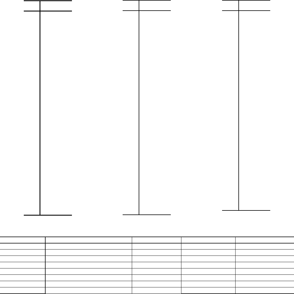
82
Table 52B — 5K Thermistor Temperature (°C) vs Resistance/Voltage
Table 53 — Pressure Transducers
*00PPG000030600A — High Pressure
00PPG000030700A — Low Pressure
TRANSDUCER ID DESCRIPTION PART NUMBER* CONNECTION POINT COMMENT
DPTA Ckt. A Discharge Pressure Transducer 00PPG000030600A MBB-J7A-CH6 —
SPTA Ckt. A Suction Pressure Transducer 00PPG000030700A MBB-J7B-CH7 —
DPTB Ckt. B Discharge Pressure Transducer 00PPG000030600A MBB-J7C-CH8 —
SPTB Ckt. B Suction Pressure Transducer 00PPG000030700A MBB-J7D-CH9 —
DPTC Ckt. C Discharge Pressure Transducer 00PPG000030600A FB3-J7-CH13 30RB210-300 Only
SPTC Ckt. C Suction Pressure Transducer 00PPG000030700A FB3-J8-CH14 30RB210-300 Only
PD.A Ckt. A Pumpdown Pressure Transducer 00PPG000030600A EMM HR-J8-CH6 Heat Reclaim Option Only
PD.B Ckt. B Pumpdown Pressure Transducer 00PPG000030600A EMM HR-J8-CH5 Heat Reclaim Option Only
TEMP
(C)
RESISTANCE
(Ohms)
–32 100,260
–31 94,165
–30 88,480
–29 83,170
–28 78,125
–27 73,580
–26 69,250
–25 65,205
–24 61,420
–23 57,875
–22 54,555
–21 51,450
–20 48,536
–19 45,807
–18 43,247
–17 40,845
–16 38,592
–15 38,476
–14 34,489
–13 32,621
–12 30,866
–11 29,216
–10 27,633
–9 26,202
–8 24,827
–7 23,532
–6 22,313
–5 21,163
–4 20,079
–3 19,058
–2 18,094
–1 17,184
0 16,325
1 15,515
2 14,749
3 14,026
4 13,342
5 12,696
6 12,085
7 11,506
8 10,959
9 10,441
10 9,949
11 9,485
12 9,044
13 8,627
14 8,231
TEMP
(C)
RESISTANCE
(Ohms)
15 7,855
16 7,499
17 7,161
18 6,840
19 6,536
20 6,246
21 5,971
22 5,710
23 5,461
24 5,225
25 5,000
26 4,786
27 4,583
28 4,389
29 4,204
30 4,028
31 3,861
32 3,701
33 3,549
34 3,404
35 3,266
36 3,134
37 3,008
38 2,888
39 2,773
40 2,663
41 2,559
42 2,459
43 2,363
44 2,272
45 2,184
46 2,101
47 2,021
48 1,944
49 1,871
50 1,801
51 1,734
52 1,670
53 1,609
54 1,550
55 1,493
56 1,439
57 1,387
58 1,337
59 1,290
60 1,244
61 1,200
TEMP
(C)
RESISTANCE
(Ohms)
62 1,158
63 1,118
64 1,079
65 1,041
66 1,006
67 971
68 938
69 906
70 876
71 836
72 805
73 775
74 747
75 719
76 693
77 669
78 645
79 623
80 602
81 583
82 564
83 547
84 531
85 516
86 502
87 489
88 477
89 466
90 456
91 446
92 436
93 427
94 419
95 410
96 402
97 393
98 385
99 376
100 367
101 357
102 346
103 335
104 324
105 312
106 299
107 285

83
Service Test — Main power and control circuit power
must be on for Service Test.
The Service Test function is used to verify proper operation
of various devices within the chiller, such as condenser fan(s),
compressors, minimum load valve solenoid (if installed),
cooler pump(s) and remote alarm relay. This is helpful during
the start-up procedure to determine if devices are installed
correctly. See Fig. 38-45 for 30RB wiring diagrams.
To use the Service Test mode, the Enable/Off/Remote Con-
tact switch must be in the OFF position. Use the display keys to
move to the Service Test mode. The items are described in the
Service Test table. There are two sub-modes available. Service
TestT.REQ allows for manual control of the compressors
and minimum load control. In this mode the compressors will
operate only on command. The capacity control and head pres-
sure control algorithms will be active. The condenser fans will
operate along with the EXVs. There must be a load on the
chiller of operate for an extended period of time. All circuit
safeties will be honored during the test. Service TestQUIC
allows for test of EXVs, condenser fans, pumps, low ambient
head pressure control speed control, crankcase and cooler heat-
ers, and status points (alarm relays, running status and chiller
capacity). This mode allows for the testing of non-refrigeration
items. If there are no keys pressed for 5 minutes, the active test
mode will be disabled.
To enter the Manual Control mode, the Enable/Off/Remote
Contact switch must be in the OFF position. Move the LED to
the Service Test mode. Press to access TEST. Press
to access T.REQ. Press and the display
will show OFF. Press and OFF will flash. Enter the
password if required. Use either arrow key to change the
T.REQ value to ON and press . Manual Control
mode is now active. Press the arrow keys to move to the appro-
priate item. To activate an item locate the item, press
and the display will show OFF. Press and OFF will
flash. Use either arrow key to change the value to ON and
press . The item should be active. To turn the item
off, locate the item, press and the display will show
ON. The chiller must be enabled by turning the Enable/Off/
Remote Contact switch to Enable. Press and ON will
flash. Use either arrow key to change the value to OFF and
press . The item should be inactive.
To enter the Quick Test mode, the Enable/Off/Remote
Contact switch must be in the OFF position. Move the LED to
the Service Test mode. Press to access TEST. Use
the key until the display reads QUIC. Press to
access Q.REQ. Press and the display will show OFF.
Press and OFF will flash. Enter the password if
required. Use either arrow key to change the QUIC value to
ON and press . Quick Test mode is now active. Fol-
low the same instructions for the Manual Control mode to acti-
vate a component.
Example — Test the chilled water pump (see Table 54).
Power must be applied to the unit. Enable/Off/Remote
Contact switch must be in the OFF position.
Test the condenser fans, cooler pump(s) and alarm relay by
changing the item values from OFF to ON. These discrete
outputs are then turned off if there is no keypad activity for
10 minutes. Test the compressor and minimum load valve sole-
noid (if installed) outputs in a similar manner. The minimum
load valve solenoids will be turned off if there is no keypad
activity for 10 minutes. Compressors will stay on until the
operator turns them off. The Service Test mode will remain
enabled for as long as there is one or more compressors
running. All safeties are monitored during this test and will
turn a compressor, circuit or the machine off if required. Any
other mode or sub-mode can be accessed, viewed, or changed
during the Manual Control mode only. The STAT item (Run
StatusVIEW) will display “0” as long as the Service mode is
enabled. The TEST sub-mode value must be changed back to
OFF before the chiller can be switched to Enable or Remote
contact for normal operation.
NOTE: There may be up to a one-minute delay before the
selected item is energized.
ENTER
ENTER ENTER
ENTER
ENTER
ENTER
ENTER
ENTER
ENTER
ENTER
ENTER
ENTER
ENTER
ENTER
ENTER
ENTER

84
Table 54 — Testing the Chilled Water Pump
MODE
(Red LED)
SUB-MODE
KEYPAD
ENTRY
ITEM
DISPLAY
EXPANSION
VALUE
DESCRIPTION
(Units)
COMMENT
SERVICE TEST
Service Test Mode
TEST Manual Sequence
QUIC Q.REQ
PASS WORD
Password may be required
0111
Each will lock in the next
digit. If 0111 is not the password,
use the arrow keys to change the
password digit and press
when correct.
Q.REQ
Returns to the original field
OFF
OFF
OFF will flash
ON
The Enable/Off/Remote Contact
switch must be in the OFF
position.
Q.REQ
EXV.A
EXV.B
PMP.1
Water Exchanger
Pump 1
OFF
OFF
OFF will flash
ON
ON
Pump 1 will turn on.
ON
ON will flash
OFF
OFF
Pump 1 will turn off.
ENTER
ENTER
ENTER
ENTER
ENTER
ENTER
ENTER
ENTER
ENTER
ENTER
ENTER
ENTER
ESCAPE
ENTER
ENTER
ENTER
ENTER
ENTER

85
LEGEND FOR FIG. 38-45
ALM R — Alarm Relay
ALT R — Alert Relay
CB — Circuit Breaker
CD-HT — Condenser Heater
CL-HT — Cooler Heater
CWFS — Chilled Water Flow Switch
DLSV — Discharge Line Soleniod Valve
DPT — Discharge Pressure Transducer
ECA-A — Entering Condenser Air-Cooled, Circuit A
ECA-B — Entering Condenser Air-Cooled, Circuit B
ECW-A — Entering Condenser Water-Cooled, Circuit A
ECW-B — Entering Condenser Water-Cooled, Circuit B
EMM — Energy Management Module
ENT A/C — Entering Air-Cooled
ENT W/C — Entering Water-Cooled
EXV — Electronic Expansion Valve
FIOP — Factory-Installed Option
FM — Fan Motor
FVFD — Fan Motor Variable Frequency Drive
HEVCF — High Efficiency Variable Condenser Fan Option
HOA — Hand/Off/Auto
HOA-A — Hand/Off/Auto, Auto Setting
HR — Heat Reclaim
LCA-A — Leaving Condenser Air-Cooled, Circuit A
LCA-B — Leaving Condenser Air-Cooled, Circuit B
LCW — Leaving Condenser Water
LCW-A — Leaving Condenser Water-Cooled, Circuit A
LCW-B — Leaving Condenser Water-Cooled, Circuit B
LLSV — Liquid Line Solenoid Valve
LVG A/C — Leaving Air-Cooled
LVG W/C — Leaving Water-Cooled
LWT — Leaving Water Temperature
MLV — Minimum Load Valve
MM — Low Ambient Temperature Head Pressure Control
OAT — Outdoor Air Temperature
PDP — Pumpdown Pressure
PMP — Pump, Chilled Water
PMPI — Chilled Water Pump Interlock
PVFD — Pump Variable Frequency Drive
RDY R — Ready Relay
RRB — Reverse Rotation Board
RUN R — Run Relay
SGT — Suction Gas Thermistor
SHD R — Shutdown Relay
SPM — Scroll Protection Module
SPT — Suction Pressure Transducer
TB — Terminal Block
TRAN — Transformer
UPC — Unitary Protocol Controller
Terminal Block Connection
Marked Terminal
Unmarked Terminal
Unmarked Splice
Factory Wiring
Optional Wiring
Indicates common potential.
Does not represent wiring.
FIOP or Accessory
Wire Tag

86
Fig. 38 — Control Schematic, 30RB060-080
a30-5696
415

87
Fig. 39 — Control Schematic, 30RB090-150
a30-
415

88
Fig. 40 — Control Schematic, 30RB160-190
a30-5699
415

89
Fig. 41 — Control Schematic, 30RB210-300
a30-5701
415
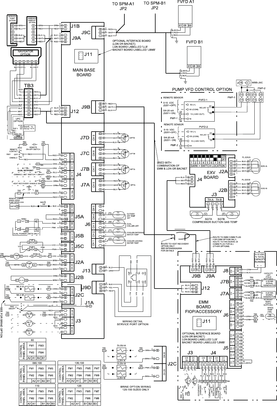
90
Fig. 42 — Control Schematic, 30RB080-150 with HEVCF Option
a30-5698
415

91
Fig. 43 — Control Schematic, 30RB160-190 with HEVCF Option
a30-5700
415
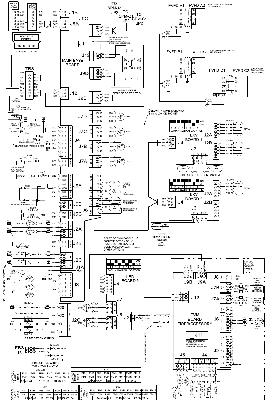
92
Fig. 44 — Control Schematic, 30RB210-300 with HEVCF Option
a30-5702
415
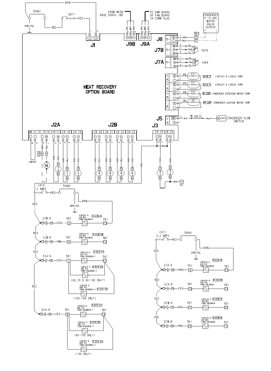
93
?????
?
?????
?
?
?
?
?
?
?
???
???
?
?
?
?
??
?????????????
????????????
?
?
?
?
?
???
???
??
?
?
?
?
?
?
?
???
???
???
?
??
???
???
?
??
?
?
??
?
?
?
?
?????????
????????
?????
?????
??????
????????
?
?
??
???
???
???
?
?
?
????
?
?
?
??
??
?
??
???
???
?
?
?
????
?
?
??
?
??
?
????
??
?
?
?
?
??
???
?
?
?????????????????????
??????
?????????????????????
?????????????????????????????
????????????????????????????
?
?
??
???
???
???
?
?
?
????
???
???
???
?
????
?
??
?
?
?
????
?
?
??????????????
??????
?
?
?????
?
??
?
?
?
?
?????
???
?
?
?
?
?????
???
??
?
?
?
?
?
?????
??
?
???
?
?
?
?
?????
???
???
?
?
?
?
?????
?
?
?
?
?
?
?
?
?
?
?????
???
?
?
?
?
?
?
?
?????
???
???
?
?
?
?????
???????
???
??????
????
???
???
???
???
?????
??
??
?
???
??
?
?
????????????
????????????
????????????
?????????
??????????????
???
???
???
???
??
???
????
?
??
??
??
???
?????????
???????
?????????????
??
???
?
???
??
??
???
?????????
???????
?????????????
??
???
?
???
??
??
???
?????????
???????
???????????????
??
???
???
?????
?????
???
?????
?????????
???????
???????????????
?????? ??????????????
?????????
???????
???????????????
??????????????
?
???
??
??
???
?????????
???????
???????????????
??
???
???
?????
?????????
???????
???????????????
?????????????
?????????
???????
???????????????
??????????
?
?????
???????
???
????????
????
???
???
???
??
??
???
?????????
???????
?????????????
??
???
??
???
??
??
???
?????????
???????
?????????????
??
???
??
???
??
??
???
?????????
???????
?????????????
??
???
???
?????
?????
???
?????
??
???
??
??
???
?????????
???????
?????????????
??
???
???
?????
??
??
???
???
?????
???????
???
????
?????
??
??
?????
?
?
?
?
????
?
??
??
?
?
???
??
??
?????
??
??
?????
??
?
?
?
????
?
?
??
?
?
???
??
??
??
??????
??????
??????
??????
???????
????????
???????
???????
???????
???????
????????
????????
????????
????????
????????
????????
????????
?
??
??????
?
?
??
???
???
?
?
?
?
?
?
?
?
??
??
???
???
Fig. 45 — Heat Reclaim Control Schematic
a30-4622

94
APPENDIXA—LOCAL DISPLAY TABLES
MODE — RUN STATUS
ITEM EXPANSION UNITS RANGE COMMENT
WRITE
STATUS
CCN TABLE CCN POINT
PAGE
NO.
VIEW AUTO VIEW OF RUN STATUS 4,83
EWT Entering Fluid Temp XXXX.X
(deg F/deg C)
0-100 STATEGEN EWT 24
LWT Leaving Fluid Temp XXX.X
(deg F/deg C)
0-100 STATEGEN LWT 24
SETP Active Setpoint XXX.X
(deg F/deg C)
0-100 GENUNIT SP 47
CTPT Control Point XXX.X
(deg F/deg C)
0-100 GENUNIT CTRL_PNT 24,43,
47
STAT Unit Run Status 0=Off
1=Running
2=Stopping
3=Delay
GENUNIT STATUS 30,31,
84
OCC Occupied NO/YES GENUNIT CHIL_OCC 30
CTRL Status Unit Control Typ 0=Local Off
1=Local On
2=CCN
3=Remote
GENUNIT ctr_type 30
CAP Percent Total Capacity XXX (%) 0-100 GENUNIT CAP_T
CAP.S Capacity Indicator XX over_cap 24
LIM Active Demand Limit Val XXX (%) 0-100 GENUNIT DEM_LIM 40
STGE Current Stage XX cur_stag
ALRM Alarm State 0=Normal
1=Partial
2=Shutdown
GENUNIT ALM
HC.ST Heat Cool Status 0=Cooling
1=Heating
2=Standby
GENUNIT HEATCOOL 24
RC.ST Reclaim Select Status NO/YES GENUNIT reclaim_sel
TIME Time of Day XX.XX 00.00-23.59 N/A TIME
MNTH Month of Year 1=January
2=February
3=March
4-April
5=May
6=June
7=July
8=August
9=September
10=October
11=November
12=December
N/A moy
DATE Day of Month XX 1-31 N/A dom
YEAR Year of Century XX 00-99 N/A yoc
R.CCN CCN FOR PRODIALOG
CH.SS CCN Chiller Start Stop ENBL/DSBL forcible GENUNIT CHIL_S_S 75
HC.SL Heat Cool Select 0=Cool
1=Heat
2=Auto
forcible GENUNIT HC_SEL
C.OCC Chiller Occupied NO/YES forcible GENUNIT CHIL_OCC
RECL Reclaim Select NO/YES forcible GENUNIT RECL_SEL
SP.OC Setpoint Occupied NO/YES forcible GENUNIT SP_OCC
D.LIM Active Demand Limit Val XXX (%) 0-100 forcible GENUNIT DEM_LIM
CTRL Control Point XXX.X
(deg F/deg C)
0-100 forcible GENUNIT CTRL_PNT
EMGY Emergency Stop ENBL/DSBL forcible GENUNIT EMSTOP
RUN UNIT RUN HOUR AND START
HRS.U Machine Operating Hours XXXX (hours) 0-999000* forcible hr_mach
STR.U Machine Starts XXXX 0-9999 forcible STRTHOUR st_mach
HR.P1 Water Pump 1 Run Hours XXXX (hours) 0-999000* forcible FANHOURS hr_cpum1
HR.P2 Water Pump 2 Run Hours XXXX (hours) 0-999000* forcible FANHOURS hr_cpum2
HR.CD Heat Reclaim Pump Hours XXXX (hours) forcible FANHOURS hr_hpump 49
HOUR COMPRESSOR RUN HOURS
HR.A1 Compressor A1 Run Hours XXXX (hours) 0-999000* forcible STRTHOUR hr_cp_a1
HR.A2 Compressor A2 Run Hours XXXX (hours) 0-999000* forcible STRTHOUR hr_cp_a2
HR.A3 Compressor A3 Run Hours XXXX (hours) 0-999000* forcible STRTHOUR hr_cp_a3
HR.A4 Compressor A4 Run Hours XXXX (hours) 0-999000* forcible STRTHOUR hr_cp_a4
HR.B1 Compressor B1 Run Hours XXXX (hours) 0-999000* forcible STRTHOUR hr_cp_b1
HR.B2 Compressor B2 Run Hours XXXX (hours) 0-999000* forcible STRTHOUR hr_cp_b2
HR.B3 Compressor B3 Run Hours XXXX (hours) 0-999000* forcible STRTHOUR hr_cp_b3
HR.B4 Compressor B4 Run Hours XXXX (hours) 0-999000* forcible STRTHOUR hr_cp_b4
HR.C1 Compressor C1 Run Hours XXXX (hours) 0-999000* forcible STRTHOUR hr_cp_c1
HR.C2 Compressor C2 Run Hours XXXX (hours) 0-999000* forcible STRTHOUR hr_cp_c2
HR.C3 Compressor C3 Run Hours XXXX (hours) 0-999000* forcible STRTHOUR hr_cp_c3
HR.C4 Compressor C4 Run Hours XXXX (hours) 0-999000* forcible STRTHOUR hr_cp_c4
STRT COMPRESSOR STARTS
ST.A1 Compressor A1 Starts XXXX 0-999000* forcible STRTHOUR st_cp_a1
ST.A2 Compressor A2 Starts XXXX 0-999000* forcible STRTHOUR st_cp_a2
ST.A3 Compressor A3 Starts XXXX 0-999000* forcible STRTHOUR st_cp_a3
ST.A4 Compressor A4 Starts XXXX 0-999000* forcible STRTHOUR st_cp_a4
ST.B1 Compressor B1 Starts XXXX 0-999000* forcible STRTHOUR st_cp_b1
ST.B2 Compressor B2 Starts XXXX 0-999000* forcible STRTHOUR st_cp_b2
ST.B3 Compressor B3 Starts XXXX 0-999000* forcible STRTHOUR st_cp_b3
ST.B4 Compressor B4 Starts XXXX 0-999000* forcible STRTHOUR st_cp_b4
ST.C1 Compressor C1 Starts XXXX 0-999000* forcible STRTHOUR st_cp_c1
ST.C2 Compressor C2 Starts XXXX 0-999000* forcible STRTHOUR st_cp_c2
ST.C3 Compressor C3 Starts XXXX 0-999000* forcible STRTHOUR st_cp_c3
ST.C4 Compressor C4 Starts XXXX 0-999000* forcible STRTHOUR st_cp_c4

95
APPENDIXA—LOCAL DISPLAY TABLES (cont)
MODE — RUN STATUS (cont)
*As data in all of these categories can exceed 9999 the following display strategy is used:
From 0-9999 display as 4 digits.
From 9999-99900 display xx.xK
From 99900-999000 display as xxxK.
ITEM EXPANSION UNITS RANGE COMMENT
WRITE
STATUS
CCN TABLE CCN POINT
PAGE
NO.
FAN FAN RUN HOURS
FR.A1 Fan 1 Run Hours Cir A XXXX (hours) 0-999000* forcible FANHOURS hr_fana1
FR.A2 Fan 2 Run Hours Cir A XXXX (hours) 0-999000* forcible FANHOURS hr_fana2
FR.A3 Fan 3 Run Hours Cir A XXXX (hours) 0-999000* forcible FANHOURS hr_fana3
FR.A4 Fan 4 Run Hours Cir A XXXX (hours) 0-999000* forcible FANHOURS hr_fana4
FR.A5 Fan 5 Run Hours Cir A XXXX (hours) 0-999000* forcible FANHOURS hr_fana5
FR.A6 Fan 6 Run Hours Cir A XXXX (hours) 0-999000* forcible FANHOURS hr_fana6
FR.B1 Fan 1 Run Hours Cir B XXXX (hours) 0-999000* forcible FANHOURS hr_fanb1
FR.B2 Fan 2 Run Hours Cir B XXXX (hours) 0-999000* forcible FANHOURS hr_fanb2
FR.B3 Fan 3 Run Hours Cir B XXXX (hours) 0-999000* forcible FANHOURS hr_fanb3
FR.B4 Fan 4 Run Hours Cir B XXXX (hours) 0-999000* forcible FANHOURS hr_fanb4
FR.B5 Fan 5 Run Hours Cir B XXXX (hours) 0-999000* forcible FANHOURS hr_fanb5
FR.B6 Fan 6 Run Hours Cir B XXXX (hours) 0-999000* forcible FANHOURS hr_fanb6
FR.C1 Fan 1 Run Hours Cir C XXXX (hours) 0-999000* forcible FANHOURS hr_fanc1
FR.C2 Fan 2 Run Hours Cir C XXXX (hours) 0-999000* forcible FANHOURS hr_fanc2
FR.C3 Fan 3 Run Hours Cir C XXXX (hours) 0-999000* forcible FANHOURS hr_fanc3
FR.C4 Fan 4 Run Hours Cir C XXXX (hours) 0-999000* forcible FANHOURS hr_fanc4
FR.C5 Fan 5 Run Hours Cir C XXXX (hours) 0-999000* forcible FANHOURS hr_fanc5
FR.C6 Fan 6 Run Hours Cir C XXXX (hours) 0-999000* forcible FANHOURS hr_fanc6
CP.UN COMPRESSOR DISABLE
A1.UN Compressor A1 Disable NO/YES forcible CP_UNABL un_cp_a1
A2.UN Compressor A2 Disable NO/YES forcible CP_UNABL un_cp_a2
A3.UN Compressor A3 Disable NO/YES forcible CP_UNABL un_cp_a3
A4.UN Compressor A4 Disable NO/YES forcible CP_UNABL un_cp_a4
B1.UN Compressor B1 Disable NO/YES forcible CP_UNABL un_cp_b1
B2.UN Compressor B2 Disable NO/YES forcible CP_UNABL un_cp_b2
B3.UN Compressor B3 Disable NO/YES forcible CP_UNABL un_cp_b3
B4.UN Compressor B4 Disable NO/YES forcible CP_UNABL un_cp_b4
C1.UN Compressor C1 Disable NO/YES forcible CP_UNABL un_cp_c1
C2.UN Compressor C2 Disable NO/YES forcible CP_UNABL un_cp_c2
C3.UN Compressor C3 Disable NO/YES forcible CP_UNABL un_cp_c3
C4.UN
Compressor C4 Disable NO/YES forcible CP_UNABL un_cp_c4
MAIN PREDICTIVE MAINTENANCE
CHRG Refrigerant Charge NO/YES SERMAINT charge_m
WATE Water Loop Size NO/YES SERMAINT wloop_m
PMP.1 Pump 1 (days) (days) SERMAINT cpump1_m
PMP.2 Pump 2 (days) (days) SERMAINT cpump2_m
PMP.C Cond Pump (days) (days) SERMAINT hpump_m
W.FIL Water Filter (days) (days) SERMAINT wfilte_m
VERS SOFTWARE VERSION
NUMBER
Press ENTER
and ESCAPE
simultaneously
to read version
information
APPL CSA-XX-XXXXXXXXX PD5_APPL
MARQ XXXXXX-XX-XX STDU
NAVI XXXXXX-XX-XX Navigator
EXV1 XXXXXX-XX-XX EXV_BRD1
EXV2 XXXXXX-XX-XX EXV_BRD2
AUX1 XXXXXX-XX-XX AUX_BRD1
AUX2 XXXXXX-XX-XX AUX_BRD2
AUX3 XXXXXX-XX-XX AUX_BRD3
AUX4 XXXXXX-XX-XX AUX_BRD4
AUX5 XXXXXX-XX-XX AUX_BRD5
CPA1 XXXXXX-XX-XX SPM_CPA1
CPA2 XXXXXX-XX-XX SPM_CPA2
CPA3 XXXXXX-XX-XX SPM_CPA3
CPA4 XXXXXX-XX-XX SPM_CPA4
CPB1 XXXXXX-XX-XX SPM_CPB1
CPB2 XXXXXX-XX-XX SPM_CPB2
CPB3 XXXXXX-XX-XX SPM_CPB3
CPB4 XXXXXX-XX-XX SPM_CPB4
CPC1 XXXXXX-XX-XX
SPM_CPC1
CPC2 XXXXXX-XX-XX SPM_CPC2
CPC3 XXXXXX-XX-XX SPM_CPC3
CPC4 XXXXXX-XX-XX SPM_CPC4
EMM XXXXXX-XX-XX EMM_NRCP

96
APPENDIXA—LOCAL DISPLAY TABLES (cont)
MODE — SERVICE TEST
*Place the Enable/Off/Remote Contact switch to the Off position prior to configuring T.REQ to ON. Configure the desired item to ON, then
place the Enable/Off/Remote Contact switch to the Enable position.
†Place the Enable/Off/Remote Contact switch to the Off position prior to configuring Q.REQ to ON. The switch should be in the Off position
to perform Quick Test.
ITEM EXPANSION UNITS RANGE COMMENT
WRITE
STATUS
CCN TABLE CCN POINT
PAGE
NO.
TEST COMPRESSORS N/A
T.REQ Manual Sequence OFF/ON* forcible N/A service_test 54,83
CP.A1 Compressor A1 Output OFF/ON forcible N/A comp_serv_a_1 54
CP.A2 Compressor A2 Output OFF/ON forcible N/A comp_serv_a_2 54
CP.A3 Compressor A3 Output OFF/ON forcible N/A comp_serv_a_3 54
CP.A4 Compressor A4 Output OFF/ON forcible N/A comp_serv_a_4 54
HGB.A Hot Gas Bypass A Output OFF/ON forcible N/A hgbp_serv_a
CP.B1 Compressor B1 Output OFF/ON forcible N/A comp_serv_b_1 54
CP.B2 Compressor B2 Output OFF/ON forcible N/A comp_serv_b_2 54
CP.B3 Compressor B3 Output OFF/ON forcible N/A comp_serv_b_3 54
CP.B4 Compressor B4 Output OFF/ON forcible N/A comp_serv_b_4 54
HGB.B Hot Gas Bypass B Output OFF/ON forcible N/A hgbp_serv_b
CP.C1 Compressor C1 Output OFF/ON forcible N/A comp_serv_c_1 54
CP.C2 Compressor C2 Output OFF/ON forcible N/A comp_serv_c_2 54
CP.C3 Compressor C3 Output OFF/ON forcible N/A comp_serv_c_3 54
CP.C4 Compressor C4 Output OFF/ON forcible N/A comp_serv_c_4 54
HGB.C Hot Gas Bypass C Output OFF/ON forcible N/A hgbp_serv_c
QUIC QUICK TEST MODE N/A 54,83
Q.REQ Quick Test Mode OFF/ON† forcible N/A test_request
EXV.A Circuit A EXV % Open XXX (%) 0-100 forcible N/A exv_qck_a 53
EXV.B Circuit B EXV % Open XXX (%) 0-100 forcible N/A exv_qck_b 53
EXV.C Circuit C EXV % Open XXX (%) 0-100 forcible N/A exv_qck_c 53
FAN.A Circuit A Fan Stages X 0-6 forcible N/A fan_qck_a
FAN.B Circuit B Fan Stages X 0-6 forcible N/A fan_qck_b
FAN.C Circuit C Fan Stages X 0-6 forcible N/A fan_qck_c
SPD.A Circ A Varifan position XXX (%) 0-100 forcible N/A hd_qck_a
SPD.B Circ B Varifan position XXX (%) 0-100 forcible N/A hd_qck_b
SPD.C Circ C Varifan position XXX (%) 0-100 forcible N/A hd_qck_c
FRV.A Free Cooling Valve A OPEN/CLSE Not supported. forcible N/A fr_qck_1a
FRP.A Refrigerant Pump Out A OFF/ON Not supported. forcible N/A fr_qck_2a
FRV.B Free Cooling Valve B OPEN/CLSE Not supported. forcible N/A fr_qck_1b
FRP.B
Refrigerant Pump Out B OFF/ON Not supported. forcible N/A fr_qck_2b
FRV.C Free Cooling Valve C OPEN/CLSE Not supported. forcible N/A fr_qck_1c
FRP.C Refrigerant Pump Out C OFF/ON Not supported. forcible N/A fr_qck_2c
RV.A 4 Way Valve Circuit A OPEN/CLSE Not supported. forcible N/A rv_qck_a
RV.B 4 Way Valve Circuit B OPEN/CLSE Not supported. forcible N/A rv_qck_b
BOIL Boiler Command OFF/ON Not supported. forcible N/A boiler_qck
HR1.A Air Cond Enter Valve A OPEN/CLSE forcible N/A hr_ea_qck_a
HR2.A Air Cond Leaving Valv A OPEN/CLSE forcible N/A hr_la_qck_a
HR3.A Water Cond Enter Valv A OPEN/CLSE forcible N/A hr_ew_qck_a
HR4.A Water Cond Leav Valve A OPEN/CLSE forcible N/A hr_lw_qck_a
HR1.B Air Cond Enter Valve B OPEN/CLSE forcible N/A hr_ea_qck_b
HR2.B Air Cond Leaving Valv B OPEN/CLSE forcible N/A hr_la_qck_b
HR3.B Water Cond Enter Valv B OPEN/CLSE forcible N/A hr_ew_qck_b
HR4.B Water Cond Leav Valve B OPEN/CLSE forcible N/A hr_lw_qck_b
PMP.1 Water Exchanger Pump 1 OFF/ON forcible N/A cpump_qck1
PMP.2 Water Exchanger Pump 2 OFF/ON forcible N/A cpump_qck2
CND.P Reclaim Condenser Pump OFF/ON forcible N/A cond_pump_qck
CL.HT Cooler Heater Output OFF/ON forcible N/A coo_heat_qck
CP.HT Condenser Heater Output OFF/ON forcible N/A cond_htr_qck
CH.A1 Compressor A1 Heater OFF/ON forcible N/A cp_ht_qck_a1
CH.A2 Compressor A2 Heater OFF/ON forcible N/A cp_ht_qck_a2
CH.A3 Compressor A3 Heater OFF/ON forcible N/A cp_ht_qck_a3
CH.A4 Compressor A4 Heater OFF/ON forcible N/A cp_ht_qck_a4
CH.B1 Compressor B1 Heater OFF/ON forcible N/A cp_ht_qck_b1
CH.B2 Compressor B2 Heater OFF/ON forcible N/A cp_ht_qck_b2
CH.B3 Compressor B3 Heater OFF/ON forcible N/A cp_ht_qck_b3
CH.B4 Compressor B4 Heater OFF/ON forcible N/A cp_ht_qck_b4
CH.C1 Compressor C1 Heater OFF/ON forcible N/A cp_ht_qck_c1
CH.C2 Compressor C2 Heater OFF/ON forcible N/A cp_ht_qck_c2
CH.C3 Compressor C3 Heater OFF/ON forcible N/A cp_ht_qck_c3
CH.C4 Compressor C4 Heater OFF/ON forcible N/A cp_ht_qck_c4
HGB.A Hot Gas Bypass A Output OFF/ON forcible N/A
HGB.B Hot Gas Bypass B Output OFF/ON forcible N/A
HGB.C Hot Gas Bypass C Output OFF/ON forcible N/A
Q.RDY Chiller Ready Status OFF/ON forcible N/A ready_qck
Q.RUN Chiller Running Status OFF/ON EMM forcible N/A running_qck
SHUT Customer Shutdown Stat OFF/ON EMM forcible N/A shutdown_qck
CATO Chiller Capacity 0-10v XX.X (vdc) 0-100 EMM forcible N/A CAPT_010_qcK
ALRM Alarm Relay OFF/ON forcible N/A alarm_qck
ALRT Alert Relay OFF/ON forcible N/A alert_qck
C.ALM Critical Alarm Relay OFF/ON Not supported. forcible N/A critical_qck

97
APPENDIXA—LOCAL DISPLAY TABLES (cont)
MODE — TEMPERATURE
MODE — PRESSURE
ITEM EXPANSION UNITS RANGE COMMENT
WRITE
STATUS
CCN TABLE CCN POINT
PAGE
NO.
UNIT ENT AND LEAVE UNIT TEMP
EWT Water Exchanger Enter XXX.X
(deg F/deg C)
–45-245 F
(–43-118 C)
STATEGEN EWT 7,47
LWT Water Exchanger Leaving XXX.X
(deg F/deg C)
–45-245 F
(–43-118 C)
STATEGEN LWT 7,47
OAT Outside Air Temperature XXX.X
(deg F/deg C)
–45-245 F
(–43-118 C)
GENUNIT OAT 7,47
CHWS Lead/Lag Leaving Fluid XXX.X
(deg F/deg C)
–45-245 F
(–43-118 C)
STATEGEN CHWS TEMP 7
HEWT Heat Reclaim Entering XXX.X
(deg F/deg C)
RECLAIM HR_EWT 17,49
HLWT Heat Reclaim Leaving XXX.X
(deg F/deg C)
RECLAIM HR_LWT 17,49
SPT Optional Space Temp XXX.X
(deg F/deg C)
–45-245 F
(–43-118 C)
STATEGEN SPACETMP 16
CIR.A TEMPERATURES CIRCUIT A
SCT.A Sat Cond Temp Circ A XXX.X
(deg F/deg C)
–45-245 F
(–43-118 C)
CIRCA_AN SCT_A
SST.A Sat Suction Temp Circ A XXX.X
(deg F/deg C)
–45-245 F
(–43-118 C)
CIRCA_AN SST_A
SGT.A Suction Gas Temp Circ A XXX.X
(deg F/deg C)
–45-245 F
(–43-118 C)
CIRCA_AN SUCT_T_A 9
SUP.A Superheat Temp Circ A XXX.X (F/C) CIRCA_AN SH_A
HRT.A Sub Condenser Gas Tmp A XXX.X
(deg F/deg C)
–45-245 F
(–43-118 C)
RECLAIM hr_subta 17
HRS.A Sub Cooling Temp A XXX.X (F/C) RECLAIM hr_subca 17,49
CIR.B TEMPERATURES CIRCUIT B
SCT.B
Sat Cond Temp Circ B XXX.X
(deg F/deg C)
–45-245 F
(–43-118 C)
CIRCB_AN SCT_B
SST.B Sat Suction Temp Circ B XXX.X
(deg F/deg C)
–45-245 F
(–43-118 C)
CIRCB_AN SST_B
SGT.B Suction Gas Temp Circ B XXX.X
(deg F/deg C)
–45-245 F
(–43-118 C)
CIRCB_AN SUCT_T_B 9
SUP.B Superheat Temp Circ B XXX.X (F/C) CIRCB_AN SH_B
HRT.B Sub Condenser Gas Tmp B XXX.X
(deg F/deg C)
–45-245 F
(–43-118 C)
RECLAIM hr_subtb 17
HRS.B Sub Cooling Temp B XXX.X (F/C) RECLAIM hr_subcb 17,49
CIR.C TEMPERATURES CIRCUIT C CIRCC_AN
SCT.C Sat Cond Temp Circ C XXX.X
(deg F/deg C)
–45-245 F
(–43-118 C)
CIRCC_AN SCT_C
SST.C Sat Suction Temp Circ C XXX.X
(deg F/deg C)
–45-245 F
(–43-118 C)
CIRCC_AN SST_C
SGT.C Suction Gas Temp Circ C XXX.X
(deg F/deg C)
–45-245 F
(–43-118 C)
CIRCC_AN SUCT_T_C 11
SUP.C Superheat Temp Circ C XXX.X (F/C) CIRCC_AN SH_C
ITEM EXPANSION UNITS RANGE COMMENT
WRITE
STATUS
CCN TABLE CCN POINT
PAGE
NO.
PRC.A PRESSURE CIRCUIT A
DP.A Discharge Pressure Cir A XXX.X
(psig/kPa)
CIRCA_AN DP_A 7,48
SP.A Suction Pressure Circ A XXX.X
(psig/kPa)
CIRCA_AN SP_A 7
PD.A Pumpdown Pressure Cir A XXX.X
(psig/kPa)
RECLAIM PD_P_A 17
PRC.B PRESSURE CIRCUIT B
DP.B Discharge Pressure Cir B XXX.X
(psig/kPa)
CIRCB_AN DP_B 7,48
SP.B Suction Pressure Circ B XXX.X
(psig/kPa)
CIRCB_AN SP_B 7
PD.B Pumpdown Pressure Cir B XXX.X
(psig/kPa)
RECLAIM PD_P_B 17
PRC.C PRESSURE CIRCUIT C
DP.C Discharge Pressure Cir C XXX.X
(psig/kPa)
CIRCC_AN DP_C 14,48
SP.C Suction Pressure Circ C XXX.X
(psig/kPa)
CIRCC_AN SP_C 14
PD.C Pumpdown Pressure Cir C XXX.X
(psig/kPa)
RECLAIM PD_P_C

98
APPENDIXA—LOCAL DISPLAY TABLES (cont)
MODE — SET POINTS
MODE — INPUTS
ITEM EXPANSION UNITS RANGE COMMENT
WRITE
STATUS
CCN TABLE CCN POINT
PAGE
NO.
COOL COOLING SETPOINTS
CSP.1 Cooling Setpoint 1 XXXX.X
(deg F/deg C)
–20-70 F
(–29-21 C),
Default = 44.0
forcible SETPOINT csp1 31,32,
43
CSP.2 Cooing Setpoint 2 XXXX.X
(deg F/deg C)
–20-70 F
(–29-21 C),
Default = 44.0
forcible SETPOINT csp2 31,32
CSP.3 Ice Setpoint XXXX.X
(deg F/deg C)
–20-70 F
(–29-21 C),
Default = 44.0
forcible SETPOINT ice_sp 31,47
CRV1 Current No Reset Val XX.X (mA) 0-20,
Default = 0
forcible SETPOINT v_cr_no 37
CRV2 Current Full Reset Val XX.X (mA) 0-20,
Default = 0
forcible SETPOINT v_cr_fu 37
CRT1 Delta T No Reset Temp XXX.X (F/C) 0-125 F
(0-69.4 C),
Default = 0
forcible SETPOINT dt_cr_no 32
CRT2 Delta T Full Reset Temp XXX.X (F/C) 0-125 F
(0-69.4 C),
Default = 0
forcible SETPOINT dt_cr_fu 32
CRO1 OAT No Reset Temp XXX.X
(deg F/deg C)
0-125 F
(–18-52 C),
Default = 14.0
forcible SETPOINT oatcr_no 32
CRO2 OAT Full Reset Temp XXX.X
(deg F/deg C)
0-25 F
(–18-52 C),
Default = 14.0
forcible SETPOINT oatcr_fu 32
CRS1 Space T No Reset Temp XXX.X
(deg F/deg C)
0-125 F
(–18-52 C),
Default = 14.0
forcible SETPOINT spacr_no 37
CRS2 Space T Full Reset Temp XXX.X
(deg F/deg C)
0-125 F
(–18-52 C),
Default = 14.0
forcible SETPOINT spacr_fu 37
DGRC Degrees Cool Reset XX.X (F/C) –30-30 F
(–16.7-16.7 C),
Default = 0
forcible SETPOINT cr_deg 32,37
CAUT Cool Changeover Setpt XX.X
(deg F/deg C)
Default = 75.0 Not supported. forcible SETPOINT cauto_sp
CRMP Cool Ramp Loading X.X 0.2-2.0 F
(0.1-1.1 C),
Default = 1.0
forcible cramp_sp 18,24
HEAT HEATING SETPOINTS
HSP.1 Heating Setpoint 1 XXX.X
(deg F/deg C)
Default = 100 Not supported. forcible SETPOINT HSP.1
HSP.2 Heating Setpoint 2 XXX.X
(deg F/deg C)
Default = 100 Not supported. forcible SETPOINT HSP.2
HRV1 Current No Reset Val XX.X (mA) Default = 0 Not supported. forcible SETPOINT v_hr_no
HRV2 Current Full Reset Val XX.X (mA) Default = 0 Not supported. forcible SETPOINT v_hr_fu
HRT1 Delta T No Reset Temp XXX.X (F/C) Default = 0 Not supported. forcible SETPOINT dt_hr_no
HRT2 Delta T Full Reset Temp XXX.X (F/C) Default = 0 Not supported. forcible SETPOINT dt_hr_fu
HRO1 OAT No Reset Temp XXX.X
(deg F/deg C)
Default = 14.0 Not supported. forcible SETPOINT oathr_no
HRO2 OAT Full Reset Temp XXX.X
(deg F/deg C)
Default = 14.0 Not supported. forcible SETPOINT oathr_fu
DGRH Degrees Heat Reset XX.X (F/C) Default = 0 Not supported. forcible SETPOINT DGRH
HAUT Heat Changeover Setpt XX.X
(deg F/deg C)
Default = 64 Not supported. forcible SETPOINT hauto_sp
HRMP Heat Ramp Loading X.X Default = 1.0 Not supported. forcible SETPOINT hramp_sp
MISC MISCELLANEOUS SETPOINTS
DLS1 Switch Limit Setpoint 1 XXX (%) 0-100,
Default = 100
forcible SETPOINT lim_sp1 40
DLS2 Switch Limit Setpoint 2 XXX (%) 0-100,
Default = 100
forcible SETPOINT lim_sp2 40
DLS3 Switch Limit Setpoint 3 XXX (%) 0-100,
Default = 100
forcible SETPOINT lim_sp3 40
RSP Heat Reclaim Setpoint XXX.X
(deg F/deg C)
Default = 122 forcible SETPOINT rsp 49
RDB Reclaim Deadband XX.X (F/C) Default = 9.0 forcible SETPOINT hr_deadb 49
ITEM EXPANSION UNITS RANGE COMMENT
WRITE
STATUS
CCN TABLE CCN POINT
PAGE
NO.
GEN.I GENERAL INPUTS
ONOF On Off Switch OPEN/CLSE STATEGEN ONOF 7
LOCK Cooler Interlock OPEN/CLSE STATEGEN LOCK_1 7,24
DLS1 Demand Limit Switch 1 OPEN/CLSE STATEGEN LIM_SW1 7
DLS2 Demand Limit Switch 2 OPEN/CLSE STATEGEN LIM_SW2 16,40
ICE.D Ice Done OFF/ON STATEGEN ICE_SW 16,40
DUAL Dual Setpoint Switch OFF/ON STATEGEN SETP_SW 7
ELEC Electrical Box Safety OPEN/CLSE STATEGEN ELEC_BOX 7
PUMP Pump Run Feedback OFF/ON STATEGEN PUMP_DEF 7
OCCS Occupancy Override Swit OFF/ON STATEGEN OCC_OVSW 16
RECL Heat Reclaim Switch OFF/ON STATEGEN RECL_SW 49
HC.SW Heat Cool Switch Status OFF/ON STATEGEN HC_SW
RLOC Remote Interlock Switch OPEN/CLSE STATEGEN REM-LOCK 16
C.FLO Reclaim Cond Flow OPEN/CLSE STATEGEN CONDFLOW 17
DMND 4-20 mA Demand Signal XXX.X (mA) 4 to 20 STATEGEN LIM_ANAL 16,41
RSET 4-20 mA Reset/Setpoint XXX.X (mA) 4 to 20 STATEGEN SP_RESET 16

99
APPENDIXA—LOCAL DISPLAY TABLES (cont)
MODE — OUTPUTS
ITEM EXPANSION UNITS RANGE COMMENT
WRITE
STATUS
CCN TABLE CCN POINT
PAGE
NO.
CIR.A OUTPUTS CIRCUIT A
CP.A1 Compressor A1 Relay OFF/ON CIRCA_D CP_A1 9
CP.A2 Compressor A2 Relay OFF/ON CIRCA_D CP_A2 9
CP.A3 Compressor A3 Relay OFF/ON CIRCA_D CP_A3 9
CP.A4 Compressor A4 Relay OFF/ON CIRCA_D CP_A4 9
HGB.A Hot Gas Bypass Circ A OFF/ON CIRCA_D HGBP_A 7
HT.A1 Comp A1 Heater Relay OFF/ON CIRCA_D cp_a1_ht 9
HT.A2 Comp A2 Heater Relay OFF/ON CIRCA_D cp_a2_ht 9
HT.A3 Comp A3 Heater Relay OFF/ON CIRCA_D cp_a3_ht 9
HT.A4 Comp A4 Heater Relay OFF/ON CIRCA_D cp_a4_ht 9
FAN.A Circuit A Fan Stages X 0-6 CIRCA_D FAN_ST_A
SPD.A Circ A Varifan Position XXX (%) 0-100 CIRCA_AN hd_pos_a 12
EXV.A Circuit A EXV % Open XXX (%) 0-100 CIRCA_AN EXV_A 9
FRP.A Refrigerant Pump Out A OFF/ON Not supported. CIRCA_D FR_PMP_A
FRVA Free Cooling Valve A OPEN/CLSE Not supported. CIRCA_D FR_VLV_A
HR1.A Air Cond Enter Valve A OPEN/CLSE RECLAIM hr_ca_a 17
HR2.A Air Cond Leaving Valv A OPEN/CLSE RECLAIM hr_la_a 17
HR3.A Water Cond Enter Valv A OPEN/CLSE RECLAIM hr_en_a 17
HR4.A Water Cond Leav Valve A OPEN/CLSE RECLAIM hr_lw_a 17
RV.A 4 Way Valve Circuit A OPEN/CLSE Not supported. CIRCA_D RV_A
CIR.B OUTPUTS CIRCUIT B
CP.B1 Compressor B1 Relay OFF/ON CIRCB_D CP_B1 9
CP.B2 Compressor B2 Relay OFF/ON CIRCB_D CP_B2 9
CP.B3 Compressor B3 Relay OFF/ON CIRCB_D CP_B3 9
CP.B4 Compressor B4 Relay OFF/ON CIRCB_D CP_B4 9
HGB.B Hot Gas Bypass Circ B OFF/ON CIRCB_D HGBP_B 7
HT.B1 Comp B1 Heater Relay OFF/ON CIRCB_D CP_HT_B1 9
HT.B2 Comp B2 Heater Relay OFF/ON CIRCB_D CP_HT_B2 9
HT.B3 Comp B3 Heater Relay OFF/ON CIRCB_D CP_HT_B3 9
HT.B4 Comp B4 Heater Relay OFF/ON CIRCB_D CP_HT_B4 9
FAN.B Circuit B Fan Stages X 0-6 CIRCB_D FAN_ST_B
SPD.B Circ B Varifan Position XXX (%) 0-100 CIRCB_AN hd_pos_b 12,13
EXV.B Circuit B EXV % Open XXX (%) 0-100 CIRCB_AN EXV_B 9
FRP.B Refrigerant Pump Out B OFF/ON Not supported. CIRCB_D FR_PMP_B
FRVB Free Cooling Valve B OPEN/CLSE Not supported. CIRCA_D FR_VLV_B
HR1.B Air Cond Enter Valve B OPEN/CLSE RECLAIM hr_ca_b 17
HR2.B Air Cond Leaving Valv B OPEN/CLSE RECLAIM hr_la_b 17
HR3.B Water Cond Enter Valv B OPEN/CLSE RECLAIM hr_en_b 17
HR4.B Water Cond Leav Valve B OPEN/CLSE RECLAIM hr_lw_b 17
RV.B 4 Way Valve Circuit B OPEN/CLSE Not supported. CIRCB_D RV_B
CIR.C OUTPUTS CIRCUIT C
CP.C1 Compressor C1 Relay OFF/ON CIRCC_D CP_C1 9
CP.C2 Compressor C2 Relay OFF/ON CIRCC_D CP_C2 9
CP.C3 Compressor C3 Relay OFF/ON CIRCC_D CP_C3 9
CP.C4 Compressor C4 Relay OFF/ON CIRCC_D CP_C4 9
HGB.C Hot Gas Bypass Circ C OFF/ON CIRCC_D HGBP_C 14
HT.C1 Comp C1 Heater Relay OFF/ON CIRCC_D cp_c1_ht 9
HT.C2 Comp C2 Heater Relay OFF/ON CIRCC_D cp_c2_ht 9
HT.C3 Comp C3 Heater Relay OFF/ON CIRCC_D cp_c3_ht 9
HT.C4 Comp C4 Heater Relay OFF/ON CIRCC_D cp_c4_ht 9
FAN.C Circuit C Fan Stages X 0-6 CIRCC_D FAN_ST_C
SPD.C Circ C Varifan Position XXX (%) 0-100 CIRCC_AN hd_pos_c 14
EXV.C Circuit C EXV % Open XXX (%) 0-100 CIRCC_AN EXV_C 11
FRP.C Refrigerant Pump Out C OFF/ON Not supported. CIRCC_D FR_PMP_ C
FRVC Free Cooling Valve C OPEN/CLSE Not supported. CIRCC_D FR_VLV_C
GEN.O GENERAL OUTPUTS
PMP.1 Water Exchanger Pump 1 OFF/ON STATEGEN CPUMP_1 7
PMP.2 Water Exchanger Pump 2 OFF/ON STATEGEN CPUMP_2 7
CND.P Reclaim Condenser Pump OFF/ON STATEGEN COND_PUMP 17
CO.HT Cooler Heater Output OFF/ON STATEGEN COOLHEAT 7
CN.HT Condenser Heater Output OFF/ON RECLAIM cond_htr 17
REDY Chiller Ready Status OFF/ON forcible RECLAIM READY 7
RUN Chiller Running Status OFF/ON forcible STATEGEN RUNNING 16
SHUT Customer Shutdown Stat OFF/ON forcible STATEGEN SHUTDOWN 16
CATO Chiller Capacity 0-10 v XX.X forcible STATEGEN CAPT_010 16
ALRM Alarm Relay OFF/ON STATEGEN ALARM 7
ALRT
Alert Relay OFF/ON STATEGEN ALERT 7
BOIL Boiler Command OFF/ON Not supported. STATEGEN BOILER
C.ALM Critical Alarm Relay OFF/ON forcible STATEGEN critical_qck

100
APPENDIXA—LOCAL DISPLAY TABLES (cont)
MODE — CONFIGURATION
ITEM EXPANSION UNITS RANGE COMMENT
WRITE
STATUS
DEFAULT
CCN
TABLE
CCN
POINT
PAGE
NO.
DISP DISPLAY CONFIGURATION
TEST Test Display LED’s OFF/ON OFF N/A display_test
METR Metric Display US/METR US DISPCONF DISPUNIT
LANG Language Selection 0=English
1=Espanol
2=Francais
3=Portugues
4=Translated
0 DISPCONF LANGUAGE 4
UNIT UNIT CONFIGURATION
TYPE Unit Type 1=Air Cooled
2=Heat Pump
Heat pump not
supported
1 FACTORY unit_typ
TONS Unit Size XXX (tons) 56 to 300
(nominal size —
refer to Table 1 for
unit modular
combinations)
FACTORY unitsize 73
VAR.A Nb Fan on Varifan Cir A X 0-6 0: Std. unit, no fan
drive options
1: Low ambient
option.
For HEVCF option
set to number of
fans on circuit:
Size 60-70 —n/a
Size 80 — 2
Size 90-120 — 3
Size 130-150 — 4
Size 160-190 — 6
Size 210-250 — 4
Size 275-300 — 6
FACTORY varfan_a
VAR.B Nb Fan on Varifan Cir B X 0-6 0: Std. unit, no fan
drive options
1: Low ambient
option.
For HEVCF option
set to number of
fans on circuit:
Size 60-70 —n/a
Size 80 — 2
Size 90-110 — 3
Size 120-170 — 4
Size 190 — 6
Size 210-250 — 4
Size 275-300 — 6
FACTORY varfan_b
VAR.C Nb Fan on Varifan Cir C X 0-6 0: Std. unit, no fan
drive options
1: Low ambient
option.
For HEVCF option
set to number of
fans on circuit:
Size 210-225 — 4
Size 250 — 6
Size 275 — 4
Size 300 — 6
FACTORY varfan_c
HGBP Hot Gas Bypass Control 0=Unused
1=Startup Only
2=Close Ctrl
3=High Ambient
1 is default for
med. temp.
brine units
(FLUD=2)
0 FACTORY hgbp_sel 18,
21-24
60HZ 60 Hz Frequency NO/YES YES FACTORY freq_60H
RECL Heat Reclaim Select NO/YES NO FACTORY recl_opt 48
EHS Electrical Heater Stage 0-4 Not supported 0 FACTORY ehs_sel
EMM EMM Module Installed NO/YES NO FACTORY emm_nrcp 72
PAS.E Password Enable
Password Protection Must Be
Disabled to Change Password
DSBL/ENBL ENBL FACTORY pass_enb
PASS Password XXX 1 to 0150 0111 FACTORY fac_pass
FREE Free Cooling Select NO/YES Not supported. NO FACTORY freecool
PD4.D Pro_Dialog User Display NO/YES Must be set to
NO
NO FACTORY pd4_disp
BOIL Boiler Command Select OFF/ON Not supported. OFF FACTORY boil_sel
VLT.S VLT Fan Drive Select 0=No fan drive
1=Low ambient
option
2=HEVCF option
0 FACTORY Vh_sel
RPM.F VLT Fan Drive RPM XXXX 0 to 1140 1140 Low
Ambient or
HEVCF option
1140 FACTORY Vh_rpm
MCHX MCHX Exchanger Select NO/YES NO FACTORY mchx_sel
FC Factory Country Code X 0 to 1 1=USA 1 FACTORY fac_code
VFDV VFD Voltage for USA Volts 208,380,460,575 Volts Voltage dependent FACTORY vfd_volt
QMFD Special Demand 0 to 255 Not supported 0 FACTORY qm_field

101
APPENDIXA—LOCAL DISPLAY TABLES (cont)
MODE — CONFIGURATION (cont)
ITEM EXPANSION UNITS RANGE COMMENT DEFAULT CCN TABLE CCN POINT
PAGE
NO.
SERV SERVICE CONFIGURATION
FLUD Cooler Fluid Type 1=Water
2=Brine
3=Low Brine
Low Brine is
not supported.
1 SERVICE1 flui_typ 18,23-
25,31,4
6,48,73
,74
MOP EXV MOP Setpoint XX.X
(deg F/deg C)
40-60 F
(4.4-15.6 C)
50 SERVICE1 mop_sp 74
HP.TH High Pressure Threshold XXX.X (psi/kPa) 500-640 psi
(3447 to
4412 kPa)
609 SERVICE1 hp_th 24
SHP.A Cir A Superheat Setp XX.X (F/C) 3-14 F
(1.7-7.8 C)
9.0 SERVICE1 sh_sp_a 74
SHP.B Cir B Superheat Setp XX.X (F/C) 3-14 F
(1.7-7.8 C)
9.0 SERVICE1 sh_sp_b 74
SHP.C Cir C Superheat Setp XX.X (F/C) 3-14 F
(1.7-7.8 C)
9.0 SERVICE1 sh_sp_c 74
HTR Cooler Heater DT Setp XX.X (F/C) 0.5-9 F
(0.3-5.0 C)
2.0 (Number of degrees added
to brine freeze set point to
enable cooler heater.)
SERVICE1 heatersp 46,56
EWTO Entering Water Control NO/YES NO SERVICE1 ewt_opt 31
AU.SM Auto Start When SM Lost NO/YES NO SERVICE1 auto_sm 75
BOTH HSM Both Command Select NO/YES NO USER both_sel
LLWT Brine Min. Fluid Temp. XX
(deg F/deg C)
–20-38 F
(–28.9-3.3)
28.0 (3.3) USER Mini_Lwt
LOSP Brine Freeze Setpoint XX.X
(deg F/deg C)
–4-50 F
(–20-10 C)
34.0 SERVICE1 lowestsp 24,25,3
1,46,48
,56,73
HD.PG Varifan Proportion Gain XX.X –10-10 Std. Unit and Low Amb.: 2.0
HEVCF: 1.0
SERVICE1 hd_pg
HD.DG Varifan Derivative Gain XX.X –10-10 Std. Unit and Low Amb.: 0.4
HEVCF: 0.1
SERVICE1 hd_dg
HD.IG Varifan Integral Gain XX.X –10-10 Std. Unit and Low Amb.: 0.2
HEVCF: 0.1
SERVICE1 hd_ig
HR.MI Reclaim Water Valve Min XXX.X (%) 20 SERVICE1 min_3w
HR.MA Reclaim Water Valve Max XXX.X (%) 100 SERVICE1 max_3w
AVFA Attach Drive to Fan A NO/YES Not supported. NO
AVFB Attach Drive to Fan B NO/YES Not supported. NO
AVFC Attach Drive to Fan C NO/YES Not supported. NO

102
APPENDIXA—LOCAL DISPLAY TABLES (cont)
MODE — CONFIGURATION (cont)
ITEM EXPANSION UNITS RANGE COMMENT DEFAULT CCN TABLE CCN POINT
PAGE
NO.
OPTN UNIT OPTIONS 2 CONTROLS
CCNA CCN Address XXX 1-239 1 N/A CCNA 45
CCNB CCN Bus Number XXX 0-239 0 N/A CCNB 46
BAUD CCN Baud Rate 1=2400
2=4800
3=9600
4=19200
5=38400
3 N/A BAUD
LOAD Loading Sequence Select 0=Equal
1=Staged
0 USER seq_typ 21,22,
LLCS Lead/Lag Circuit Select 0=Automatic
1=Cir A Leads
2=Cir B Leads
3=Cir C Leads
0 USER lead_cir 21,22
RL.S Ramp Load Select ENBL/DSBL DSBL USER ramp_sel 18,24,
46
DELY Minutes Off Time XX (Minutes) 1 to 15 1 USER off_on_d 18,30,
46,75
ICE.M Ice Mode Enable ENBL/DSBL DSBL USER ice_cnfg 31
PUMP Cooler Pumps Sequence 0=No Pump
1=1 Pump Only
2=2 Pumps Auto
3=PMP 1 Manual
4=PMP 2 Manual
0 USER pump_seq 29,30,
43,46
ROT.P Pump Rotation Delay XXXX (hours) 24 to 3000 48 USER pump_del 46
PM.PS Periodic Pump Start NO-YES NO USER pump_per 30,48
P.SBY Stop Pump In Standby NO-YES NO USER pump_sby
P.LOC Flow Checked if Pmp Off NO-YES YES USER pump_loc 30
LS.ST Night Low Noise Start XX.XX 00.00-23.59 00.00 USER nh_start 30
LS.ND Night Low Noise End XX.XX 00-00-23.59 00.00 USER nh_end 47
LS.LT Low Noise Capacity Lim XXX (%) 0-100 100 USER nh_limit 46,47
OA.TH Heat Mode OAT Threshold XX.X
(deg F/deg C)
Not supported. 5 F USER heat_th
FREE Free Cooling OAT Limit XX.X
(deg F/deg C)
Not supported. 32.0 USER free_oat
BO.TH Boiler OAT Threshold XX.X
(deg F/deg C)
5-32 F
(–15-0 C)
Not supported. 14 USER boil_th
EHST Elec Stag OAT Threshold XX.XX
(deg F/deg C)
23 -70 F
(–5-21 C)
Not supported. 41 USER ehs_th
EHSB Last Heat Elec Backup NO-YES Not supported. NO USER ehs_back
E.DEF Quick EHS in Defrost NO-YES Not supported. NO USER ehs_defr
EHSP Elec Heating Pulldown XX (min) Not supported. 0 USER ehs_pull
AUTO Auto Changeover Select NO-YES Not supported. NO USER auto_sel
RSET
RESET, COOL AND HEAT TEMP
CRST Cooling Reset Type 0=No Reset
1=Out Air Temp
2=Delta T Temp
3=4-20 mA Input
4=Space Temp
0 USER cr_sel 32,37,
46
HRST Heating Reset Type 0=No Reset
1=Out Air Temp
2=Delta T Temp
3=4-20 mA Input
Not supported. 0 USER hr_sel
DMDC Demand Limit Select 0=None
1=Switch
2=4-20 mA Input
0 USER lim_sel 40,41,
46
DMMX mA for 100% Demand Lim XX.X (mA) 0.0 USER lim_mx 41
DMZE mA for 0% Demand Limit XX.X (mA) 0.0 USER lim_ze 41
MSSL Master/Slave Select 0=Disable
1=Master
2=Slave
0 MST_SLV ms_sel 46,47,
73,75
SLVA Slave Address XXX 1-236 2 MST_SLV slv_addr
LLBL Lead/Lag Balance Select ENBL/DSBL DSBL MST_SLV ll_bal 18,45,
46
LLBD Lead/Lag Balance Delta XXX (hours) 40-400 168 MST_SLV ll_bal_d 18,45,
46
LLDY Lag Start Delay XX (minutes) 2-30 10 MST_SLV lsrt_tim 18,45
LAGP Lag Unit Pump Select 0=Off if Unit
stopped
1=On if Unit
stopped
0 MST_SLV lag_pump 18,21,
45
LPUL Lead Pulldown Time XX (minutes) 0-60 0 MST_SLV lead_pul 18,45

103
APPENDIXA—LOCAL DISPLAY TABLES (cont)
MODE — TIMECLOCK
*Password protected.
ITEM EXPANSION UNITS RANGE COMMENT
WRITE
STATUS
CCN TABLE CCN POINT
PAGE
NO.
TIME TIME OF DAY
HH.MM Hour and Minute XX.XX 00.00-23.59 forcible* N/A HH.MM
DATE MONTH DATE DAY AND YEAR
MNTH Month of Year 1=January
2=February
3=March
4=April
5=May
6=June
7=July
8=August
9=September
10=October
11=November
12=December
forcible* N/A MNTH
DOM Day of Month XX 1-31 forcible* N/A DOM
DAY Day of Week 1=Monday
2=Tuesday
3=Wednesday
4=Thursday
5=Friday
6=Saturday
7=Sunday
forcible* N/A DAY
YEAR Year of Century XX 00-99 forcible* N/A YEAR
SCH1 TIME SCHEDULE 1 30
PER.1 Period 1 Occ/Unocc Sel
PER.1OCC.1 Occupied Time XX.XX 00.00-23.59 forcible OCC1P01S OCCTOD1
PER.1UNO.1 Unoccupied Time XX.XX 00.00-23.59 forcible OCC1P01S UNOCTOD1
PER.1MON.1 Monday Select NO/YES forcible OCC1P01S DOW1
PER.1TUE.1 Tuesday Select NO/YES forcible OCC1P01S DOW1
PER.1WED.1 Wednesday Select NO/YES forcible OCC1P01S DOW1
PER.1THU.1 Thursday Select NO/YES forcible OCC1P01S DOW1
PER.1FRI.1 Friday Select NO/YES forcible OCC1P01S DOW1
PER.1SAT.1 Saturday Select NO/YES forcible OCC1P01S DOW1
PER.1SUN.1 Sunday Select NO/YES forcible OCC1P01S DOW1
PER.1HOL.1 Holiday Select NO/YES forcible OCC1P01S DOW1
PER.2 Period 2 Occ/Unocc Sel OCC1P01S
PER.2OCC.2 Occupied Time XX.XX 00.00-23.59 forcible OCC1P01S OCCTOD2
PER.2UNO.2 Unoccupied Time XX.XX 00.00-23.59 forcible OCC1P01S UNOCTOD2
PER.2
MON.2 Monday Select NO/YES forcible OCC1P01S DOW2
PER.2TUE.2 Tuesday Select NO/YES forcible OCC1P01S DOW2
PER.2WED.2 Wednesday Select NO/YES forcible OCC1P01S DOW2
PER.2THU.2 Thursday Select NO/YES forcible OCC1P01S DOW2
PER.2FRI.2 Friday Select NO/YES forcible OCC1P01S DOW2
PER.2SAT.2 Saturday Select NO/YES forcible OCC1P01S DOW2
PER.2SUN.2 Sunday Select NO/YES forcible OCC1P01S DOW2
PER.2HOL.2 Holiday Select NO/YES forcible OCC1P01S DOW2
PER.3 Period 3 Occ/Unocc Sel OCC1P01S
PER.3OCC.3 Occupied Time XX.XX 00.00-23.59 forcible OCC1P01S OCCTOD3
PER.3UNO.3 Unoccupied Time XX.XX 00.00-23.59 forcible OCC1P01S UNOCTOD3
PER.3MON.3 Monday Select NO/YES forcible OCC1P01S DOW3
PER.3TUE.3 Tuesday Select NO/YES forcible OCC1P01S DOW3
PER.3WED.3 Wednesday Select NO/YES forcible OCC1P01S DOW3
PER.3THU.3 Thursday Select NO/YES forcible OCC1P01S DOW3
PER.3FRI.3 Friday Select NO/YES forcible OCC1P01S DOW3
PER.3SAT.3 Saturday Select NO/YES forcible OCC1P01S DOW3
PER.3SUN.3 Sunday Select NO/YES forcible OCC1P01S DOW3
PER.3HOL.3 Holiday Select NO/YES forcible OCC1P01S DOW3
PER.4 Period 4 Occ/Unocc Sel
PER.4OCC.4 Occupied Time XX.XX 00.00-23.59 forcible OCC1P01S OCCTOD4
PER.4UNO.4 Unoccupied Time XX.XX 00.00-23.59 forcible OCC1P01S UNOCTOD4
PER.4MON.4 Monday Select NO/YES forcible OCC1P01S DOW4
PER.4TUE.4 Tuesday Select NO/YES forcible OCC1P01S DOW4
PER.4WED.4 Wednesday Select NO/YES forcible OCC1P01S DOW4
PER.4THU.4 Thursday Select NO/YES forcible OCC1P01S DOW4
PER.4FRI.4 Friday Select NO/YES forcible OCC1P01S DOW4
PER.4SAT.4 Saturday Select NO/YES forcible OCC1P01S DOW4
PER.4SUN.4 Sunday Select NO/YES forcible OCC1P01S DOW4
PER.4HOL.4 Holiday Select NO/YES forcible OCC1P01S DOW4
PER.5 Period 5 Occ/Unocc Sel
PER.5OCC.5 Occupied Time XX.XX 00.00-23.59 forcible OCC1P01S OCCTOD5
PER.5UNO.5 Unoccupied Time XX.XX 00.00-23.59 forcible OCC1P01S UNOCTOD5
PER.5MON.5 Monday Select NO/YES forcible OCC1P01S DOW5
PER.5TUE.5 Tuesday Select NO/YES forcible OCC1P01S DOW5
PER.5WED.5 Wednesday Select NO/YES forcible OCC1P01S DOW5
PER.5THU.5 Thursday Select NO/YES forcible OCC1P01S DOW5
PER.5FRI.5 Friday Select NO/YES forcible OCC1P01S DOW5
PER.5SAT.5 Saturday Select NO/YES forcible OCC1P01S DOW5
PER.5SUN.5 Sunday Select NO/YES forcible OCC1P01S DOW5
PER.5HOL.5 Holiday Select NO/YES forcible OCC1P01S DOW5
PER.6 Period 6 Occ/Unocc Sel
PER.6
OCC.6 Occupied Time XX.XX 00.00-23.59 forcible OCC1P01S OCCTOD6
PER.6UNO.6 Unoccupied Time XX.XX 00.00-23.59 forcible OCC1P01S UNOCTOD6
PER.6MON.6 Monday Select NO/YES forcible OCC1P01S DOW6
PER.6TUE.6 Tuesday Select NO/YES forcible OCC1P01S DOW6
PER.6WED.6 Wednesday Select NO/YES forcible OCC1P01S DOW6
PER.6THU.6 Thursday Select NO/YES forcible OCC1P01S DOW6
PER.6FRI.6 Friday Select NO/YES forcible OCC1P01S DOW6
PER.6SAT.6 Saturday Select NO/YES forcible OCC1P01S DOW6
PER.6SUN.6 Sunday Select NO/YES forcible OCC1P01S DOW6
PER.6HOL.6 Holiday Select NO/YES forcible OCC1P01S DOW6

104
APPENDIXA—LOCAL DISPLAY TABLES (cont)
MODE — TIMECLOCK (cont)
ITEM EXPANSION UNITS RANGE COMMENT
WRITE
STATUS
CCN TABLE CCN POINT
PAGE
NO.
SCH1 TIME SCHEDULE 1 30,32
PER.7 Period 7 Occ/Unocc Sel
PER.7OCC.7 Occupied Time XX.XX 00.00-23.59 forcible OCCP01S OCCTOD7
PER.7UNO.7 Unoccupied Time XX.XX 00.00-23.59 forcible OCCP01S UNOCTOD7
PER.7MON.7 Monday Select NO/YES forcible OCCP01S DOW7
PER.7TUE.7 Tuesday Select NO/YES forcible OCCP01S DOW7
PER.7WED.7 Wednesday Select NO/YES forcible OCCP01S DOW7
PER.7THU.7 Thursday Select NO/YES forcible OCCP01S DOW7
PER.7FRI.7 Friday Select NO/YES forcible OCCP01S DOW7
PER.7SAT.7 Saturday Select NO/YES forcible OCCP01S DOW7
PER.7SUN.7 Sunday Select NO/YES forcible OCCP01S DOW7
PER.7HOL.7 Holiday Select NO/YES forcible OCCP01S DOW7
PER.8 Period 8 Occ/Unocc Sel OCCP01S
PER.8OCC.8 Occupied Time XX.XX 00.00-23.59 forcible OCCP01S OCCTOD8
PER.8UNO.8 Unoccupied Time XX.XX 00.00-23.59 forcible OCCP01S UNOCTOD8
PER.8MON.8 Monday Select NO/YES forcible OCCP01S DOW8
PER.8TUE.8 Tuesday Select NO/YES forcible OCCP01S DOW8
PER.8WED.8 Wednesday Select NO/YES forcible OCCP01S DOW8
PER.8THU.8 Thursday Select NO/YES forcible OCCP01S DOW8
PER.8FRI.8 Friday Select NO/YES forcible OCCP01S DOW8
PER.8SAT.8 Saturday Select NO/YES forcible OCCP01S DOW8
PER.8SUN.8 Sunday Select NO/YES forcible OCCP01S DOW8
PER.8HOL.8 Holiday Select NO/YES forcible OCCP01S DOW8
SCH2 TIME SCHEDULE 2 30,32
PER.1 Period 1 Occ/Unocc Sel
PER.1OCC.1 Occupied Time XX.XX 00.00-23.59 forcible OCC2P02S OCCTOD1
PER.1UNO.1 Unoccupied Time XX.XX 00.00-23.59 forcible OCC2P02S UNOCTOD1
PER.1MON.1 Monday Select NO/YES forcible OCC2P02S DOW1
PER.1TUE.1 Tuesday Select NO/YES forcible OCC2P02S DOW1
PER.1WED.1 Wednesday Select NO/YES forcible OCC2P02S DOW1
PER.1THU.1 Thursday Select NO/YES forcible OCC2P02S DOW1
PER.1FRI.1 Friday Select NO/YES forcible OCC2P02S DOW1
PER.1SAT.1 Saturday Select NO/YES forcible OCC2P02S DOW1
PER.1SUN.1 Sunday Select NO/YES forcible OCC2P02S DOW1
PER.1HOL.1 Holiday Select NO/YES forcible OCC2P02S DOW1
PER.2 Period 2 Occ/Unocc Sel
PER.2OCC.2 Occupied Time XX.XX 00.00-23.59 forcible OCC2P02S OCCTOD
PER.2UNO.2 Unoccupied Time XX.XX 00.00-23.59 forcible OCC2P02S UNOCTOD2
PER.2MON.2 Monday Select NO/YES forcible OCC2P02S DOW2
PER.2TUE.2 Tuesday Select NO/YES forcible OCC2P02S DOW2
PER.2WED.2 Wednesday Select NO/YES forcible OCC2P02S DOW2
PER.2
THU.2 Thursday Select NO/YES forcible OCC2P02S DOW2
PER.2FRI.2 Friday Select NO/YES forcible OCC2P02S DOW2
PER.2SAT.2 Saturday Select NO/YES forcible OCC2P02S DOW2
PER.2SUN.2 Sunday Select NO/YES forcible OCC2P02S DOW2
PER.2HOL.2 Holiday Select NO/YES forcible OCC2P02S DOW2
PER.3 Period 3 Occ/Unocc Sel
PER.3OCC.3 Occupied Time XX.XX 00.00-23.59 forcible OCC2P02S OCCTOD
PER.3UNO.3 Unoccupied Time XX.XX 00.00-23.59 forcible OCC2P02S UNOCTOD3
PER.3MON.3 Monday Select NO/YES forcible OCC2P02S DOW3
PER.3TUE.3 Tuesday Select NO/YES forcible OCC2P02S DOW3
PER.3WED.3 Wednesday Select NO/YES forcible OCC2P02S DOW3
PER.3THU.3 Thursday Select NO/YES forcible OCC2P02S DOW3
PER.3FRI.3 Friday Select NO/YES forcible OCC2P02S DOW3
PER.3SAT.3 Saturday Select NO/YES forcible OCC2P02S DOW3
PER.3SUN.3 Sunday Select NO/YES forcible OCC2P02S DOW3
PER.3HOL.3 Holiday Select NO/YES forcible OCC2P02S DOW3
PER.4 Period 4 Occ/Unocc Sel
PER.4OCC.4 Occupied Time XX.XX 00.00-23.59 forcible OCC2P02S OCCTOD4
PER.4UNO.4 Unoccupied Time XX.XX 00.00-23.59 forcible OCC2P02S UNOCTOD4
PER.4MON.4 Monday Select NO/YES forcible OCC2P02S DOW4
PER.4TUE.4 Tuesday Select NO/YES forcible OCC2P02S DOW4
PER.4WED.4 Wednesday Select NO/YES forcible OCC2P02S DOW4
PER.4THU.4 Thursday Select NO/YES forcible OCC2P02S DOW4
PER.4FRI.4 Friday Select NO/YES forcible OCC2P02S DOW4
PER.4SAT.4 Saturday Select NO/YES forcible OCC2P02S DOW4
PER.4SUN.4 Sunday Select NO/YES forcible OCC2P02S DOW4
PER.4HOL.4 Holiday Select NO/YES forcible OCC2P02S DOW4
PER.5 Period 5 Occ/Unocc Sel
PER.5OCC.5 Occupied Time XX.XX 00.00-23.59 forcible OCC2P02S OCCTOD5
PER.5UNO.5 Unoccupied Time XX.XX 00.00-23.59 forcible OCC2P02S UNOCTOD5
PER.5MON.5 Monday Select NO/YES forcible OCC2P02S DOW5
PER.5TUE.5 Tuesday Select NO/YES forcible OCC2P02S DOW5
PER.5WED.5 Wednesday Select NO/YES forcible OCC2P02S DOW5
PER.5THU.5 Thursday Select NO/YES forcible OCC2P02S DOW5
PER.5FRI.5 Friday Select NO/YES forcible OCC2P02S DOW5
PER.5SAT.5 Saturday Select NO/YES forcible OCC2P02S DOW5
PER.5SUN.5 Sunday Select NO/YES forcible OCC2P02S DOW5
PER.5HOL.5 Holiday Select NO/YES forcible OCC2P02S DOW5
PER.6 Period 6 Occ/Unocc Sel
PER.6OCC.6 Occupied Time XX.XX 00.00-23.59 forcible OCC2P02S OCCTOD6
PER.6UNO.6 Unoccupied Time XX.XX 00.00-23.59 forcible OCC2P02S UNOCTOD6
PER.6MON.6 Monday Select NO/YES forcible OCC2P02S DOW6
PER.6
TUE.6 Tuesday Select NO/YES forcible OCC2P02S DOW6
PER.6WED.6 Wednesday Select NO/YES forcible OCC2P02S DOW6
PER.6THU.6 Thursday Select NO/YES forcible OCC2P02S DOW6
PER.6FRI.6 Friday Select NO/YES forcible OCC2P02S DOW6
PER.6SAT.6 Saturday Select NO/YES forcible OCC2P02S DOW6
PER.6SUN.6 Sunday Select NO/YES forcible OCC2P02S DOW6
PER.6HOL.6 Holiday Select NO/YES forcible OCC2P02S DOW6

105
APPENDIXA—LOCAL DISPLAY TABLES (cont)
MODE — TIMECLOCK (cont)
*Default=NO.
†Default=0.
ITEM EXPANSION UNITS RANGE COMMENT
WRITE
STATUS
CCN TABLE CCN POINT
PAGE
NO.
PER.7 Period 7 Occ/Unocc Sel
PER.7OCC.7 Occupied Time XX.XX 00.00-23.59 forcible OCC2P02S OCCTOD7
PER.7UNO.7 Unoccupied Time XX.XX 00.00-23.59 forcible UNOCTOD7
PER.7MON.7 Monday Select NO/YES forcible DOW7
PER.7TUE.7 Tuesday Select NO/YES forcible DOW7
PER.7WED.7 Wednesday Select NO/YES forcible DOW7
PER.7THU.7 Thursday Select NO/YES forcible DOW7
PER.7FRI.7 Friday Select NO/YES forcible DOW7
PER.7SAT.7 Saturday Select NO/YES forcible DOW7
PER.7SUN.7 Sunday Select NO/YES forcible DOW7
PER.7HOL.7 Holiday Select NO/YES forcible DOW7
PER.8 Period 8 Occ/Unocc Sel
PER.8OCC.8 Occupied Time XX.XX 00.00-23.59 forcible OCCTOD8
PER.8UNO.8 Unoccupied Time XX.XX 00.00-23.59 forcible UNOCTOD8
PER.8MON.8 Monday Select NO/YES forcible DOW8
PER.8TUE.8 Tuesday Select NO/YES forcible DOW8
PER.8WED.8 Wednesday Select NO/YES forcible DOW8
PER.8THU.8 Thursday Select NO/YES forcible DOW8
PER.8FRI.8 Friday Select NO/YES forcible DOW8
PER.8
SAT.8 Saturday Select NO/YES forcible DOW8
PER.8SUN.8 Sunday Select NO/YES forcible DOW8
PER.8HOL.8 Holiday Select NO/YES forcible DOW8
HOLI HOLIDAYS CONFIGURATION
HOL.1 Holidays Config 1
HOL.1MON.1 Holiday Start Month 1=January
2=February
3=March
4=April
5=May
6=June
7=July
8=August
9=September
10=October
11=November
12=December
forcible HOLDY_01 HOL_MON
HOL.1DAY.1 Holiday Start Day XX 1 to 31 forcible HOLDY_01 HOL_DAY
HOL.1DUR.1 Holiday Duration in Day XX 1 to 99 forcible HOLDY_01 HOL_LEN
HOL.1HOL.2 Holidays Config 2
HOL.1MON.2 Holiday Start Month See
HOL.1MON.1
forcible HOLDY_02 HOL_MON
HOL.2DAY.2 Holiday Start Day See
HOL.1DAY.1
forcible HOLDY_02 HOL_DAY
HOL.2DUR.2 Holiday Duration in Day See
HOL.1DUR.1
forcible HOLDY_02 HOL_LEN
HOL.9 Holidays Config 9
HOL.9MON.9 Holiday Start Month See
HOL.1MON.1
forcible HOLDY_09 HOL_MON
HOL.9DAY.9 Holiday Start Day See
HOL.1DAY.1
forcible HOLDY_09 HOL_DAY
HOL.9DUR.9 Holiday Duration in Days See
HOL.1DUR.1
forcible HOLDY_09 HOL_LEN
HOL.10HO.10
Holidays Config 10
HOL.10MO.10 Holiday Start Month See
HOL.1MON.1
forcible HOLDY_09
HOL.10DA.10 Holiday Start Day See
HOL.1DAY.1
forcible HOLDY_09
HOL.10DU.10 Holiday Duration in Days See
HOL.1DUR.1
forcible HOLDY_09
HOL.16HO.16 Holidays Config 16
HOL.16MO.16 Holiday Start Month See
HOL.1MON.1
forcible HOLDY_16
HOL.16DA.16 Holiday Start Day See
HOL.1DAY.1
forcible
HOL.16DU.16 Holiday Duration in Days See
HOL.1DUR.1
forcible
MCFG SERVICE MAINTENANCE CONFIG 76
AL.SV Service Warning Select NO/YES forcible* MAINTCFG s_alert
CHRG Refrigerant Charge NO/YES forcible* MAINTCFG charge_a
WATE Water Loop Size NO/YES forcible* MAINTCFG wloop_c
PMP.1 Pump 1 (days) XXXX (days) 0-65,500 forcible† MAINTCFG pump1_c
PMP.2 Pump 2 (days) XXXX (days) 0-65,500 forcible† MAINTCFG pump2_c
PMP.C Cond Pump (days) XXXX (days) 0-65,500 forcible† MAINTCFG hpump_c
W.FIL Water Filter (days) XXXX (days) forcible† MAINTCFG wfilte_c 43
RS.SV Servicing Alert Reset 0=Default
1=Refrigerant Charge
2=Water loop size
3=Not used
4=Pump 1
5=Pump 2
6=Reclaim Pump
7=Water filter
8=Reset all
forcible† SERMAINT s_reset

106
APPENDIXA—LOCAL DISPLAY TABLES (cont)
MODE — OPERATING MODES
NOTE: See Operating Modes starting on page 46.
MODE — ALARMS
*Expanded display will be actual alarm expansion.
†Up to five current alarms will be displayed.
**History of thirty past alarms will be displayed.
ITEM EXPANSION UNITS RANGE COMMENT
WRITE
STATUS
CCN TABLE CCN POINT
PAGE
NO.
SLCT OPERATING TYPE CONTROL
OPER Operating Type Control 0=Switch Ctrl
1=Time Sched
2=CCN Control
Default = 0 forcible N/A N/A 30,42,
45,49
SP.SE Setpoint Select 0=Setpoint Occ
1=Setpoint1
2=Setpoint2
3=4-20mA Setp
4=Dual Setp Sw
Default = 0 forcible N/A N/A 31,32
HC.SE Heat Cool Select 0=Cooling
1=Heating
2=Auto Chgover
3=Heat Cool Sw
Default = 0
1-3 not
supported.
forcible GENUNIT HC_SEL 31
RL.SE Reclaim Select 0=No
1=Yes
2=Switch Ctrl
Default = 0
Yes = CCN
control
forcible GENUNIT RECL_SEL 49
MODE MODES CONTROLLING UNIT
MD01 Startup Delay in Effect OFF/ON MODES MODE_01 46
MD02 Second Setpoint in Use OFF/ON MODES MODE_02 46
MD03 Reset in Effect OFF/ON MODES MODE_03 46
MD04 Demand Limit Active OFF/ON MODES MODE_04 46
MD05 Ramp Loading Active OFF/ON MODES MODE_05 46
MD06 Cooler Heater Active OFF/ON MODES MODE_06 46
MD07 Water Pumps Rotation OFF/ON MODES MODE_07 46
MD08 Pump Periodic Start OFF/ON MODES MODE_08 46
MD09 Night Low Noise Active OFF/ON MODES MODE_09 47
MD10 System Manager Active OFF/ON MODES MODE_10 47
MD11 Mast Slave Ctrl Active OFF/ON MODES MODE_11 47
MD12 Auto Changeover Active OFF/ON Not supported. MODES MODE_12 47
MD13 Free Cooling Active OFF/ON Not supported. MODES MODE_13 47
MD14 Reclaim Active OFF/ON MODES MODE_14 47,49
MD15 Electric Heat Active OFF/ON Not supported. MODES MODE_15 47
MD16 Heating Low EWT Lockout OFF/ON Not supported. MODES MODE_16 47
MD17 Boiler Active OFF/ON Not supported. MODES MODE_17 47
MD18 Ice Mode in Effect OFF/ON MODES MODE_18 47
MD19 Defrost Active on Cir A OFF/ON Not supported. MODES MODE_19 47
MD20 Defrost Active on Cir B OFF/ON Not supported. MODES MODE_20 47
MD21 Low Suction Circuit A OFF/ON MODES MODE_21 48
MD22 Low Suction Circuit B OFF/ON MODES MODE_22 48
MD23 Low Suction Circuit C OFF/ON MODES MODE_23 48
MD24 High DGT Circuit A OFF/ON MODES MODE_24 48
MD25 High DGT Circuit B OFF/ON MODES MODE_25 48
MD26 High DGT Circuit C OFF/ON MODES MODE_26 48
MD27 High Pres Override Cir A OFF/ON MODES MODE_27 48
MD28 High Pres Override Cir B OFF/ON MODES MODE_28 48
MD29 High Pres OVerride Cir C OFF/ON MODES MODE_29 48
MD30 Low Superheat Circuit A OFF/ON MODES MODE_30 48
MD31 Low Superheat Circuit B OFF/ON MODES MODE_31 48
MD32 Low Superheat Circuit C OFF/ON MODES MODE_32 48
ITEM EXPANSION* UNITS RANGE COMMENT
WRITE
STATUS
CCN TABLE CCN POINT
PAGE
NO.
R.ALM RESET ALL CURRENT ALRM forcible N/A N/A 62
ALRM† CURRENTLY ACTIVE ALARM 62
Current Alarm 1 GENUNIT alarm_1 62
Current Alarm 2 GENUNIT alarm_2 62
Current Alarm 3 GENUNIT alarm_3 62
Current Alarm 4 GENUNIT alarm_4 62
Current Alarm 5 GENUNIT alarm_5 62
H.ALM** ALARM HISTORY
Alarm History #1 ALRMHIST alm_history_01
Alarm History #2 ALRMHIST alm_history_02
ALRMHIST
Alarm History #29 ALRMHIST alm_history_29
Alarm History #30 ALRMHIST alm_history_30

107
APPENDIX B — CCN TABLES
STATUS DISPLAY TABLES
TABLE DISPLAY NAME RANGE UNITS POINT NAME WRITE STATUS
CIRCA_AN
Percent Total Capacity 0 - 100 % CAPA_T
Discharge Pressure nnn.n PSI DP_A
Suction Pressure nnn.n PSI SP_A
Crank Heater Current Cp1 nnn.n AMPS cpa1_cur
Crank Heater Current Cp2 nnn.n AMPS cpa2_cur
Crank Heater Current Cp3 nnn.n AMPS cpa3_cur
Crank Heater Current Cp4 nnn.n AMPS cpa4_cur
Motor Thermistor Comp 1 nnnn OHMS cpa1_tmp
Motor Thermistor Comp 2 nnnn OHMS cpa2_tmp
Motor Thermistor Comp 3 nnnn OHMS cpa3_tmp
Motor Thermistor Comp 4 nnnn OHMS cpa4_tmp
Saturated Condensing Tmp ±nnn.n °F SCT_A
Saturated Suction Temp ±nnn.n °F SST_A
Suction Gas Temperature ±nnn.n °F SUCT_T_A
Suction Superheat Temp ±nnn.n ^F SH_A
EXV Position 0 - 100 % EXV_A
Head Press Actuator Pos 0 - 100 % hd_pos_a
CIRCA_D
Compressor 1 Output On/Off CP_A1
Compressor 2 Output On/Off CP_A2
Compressor 3 Output On/Off CP_A3
Compressor 4 Output On/Off CP_A4
Compressor 1 Heater Out On/Off cp_a1_ht
Compressor 2 Heater Out On/Off cp_a2_ht
Compressor 3 Heater Out On/Off cp_a3_ht
Compressor 4 Heater Out On/Off cp_a4_ht
Hot Gas Bypass Output On/Off HGBP_V_A
Fan Output DO # 1 On/Off fan_a1
Fan Output DO # 2 On/Off fan_a2
Fan Output DO # 3 On/Off fan_a3
Fan Output DO # 4 On/Off fan_a4
Fan Output DO # 5 On/Off fan_a5
Fan Output DO # 6 On/Off fan_a6
Fan Staging Number 0-6 FAN_ST_A
4 Way Refrigerant Valve On/Off RV_A
CIRCB_AN
Percent Total Capacity 0 - 100 % CAPB_T
Discharge Pressure nnn.n PSI DP_B
Suction Pressure nnn.n PSI SP_B
Crank Heater Current Cp1 nnn.n AMPS cpb1_cur
Crank Heater Current Cp2 nnn.n AMPS cpb2_cur
Crank Heater Current Cp3 nnn.n AMPS cpb3_cur
Crank Heater Current Cp4 nnn.n AMPS cpb4_cur
Motor Thermistor Comp 1 nnnn OHMS cpb1_tmp
Motor Thermistor Comp 2 nnnn OHMS cpb2_tmp
Motor Thermistor Comp 3 nnnn OHMS cpb3_tmp
Motor Thermistor Comp 4 nnnn OHMS cpb4_tmp
Saturated Condensing Tmp ±nnn.n °F SCT_B
Saturated Suction Temp ±nnn.n °F SST_B
Suction Gas Temperature ±nnn.n °F SUCT_T_B
Suction Superheat Temp ±nnn.n ^F SH_B
EXV Position 0-100 % EXV_B
Head Press Actuator Pos 0-100 % hd_pos_b
CIRCB_D
Compressor 1 Output On/Off CP_B1
Compressor 2 Output On/Off CP_B2
Compressor 3 Output On/Off CP_B3
Compressor 4 Output On/Off CP_B4
Compressor 1 Heater Out On/Off cp_b1_ht
Compressor 2 Heater Out On/Off cp_b2_ht
Compressor 3 Heater Out On/Off cp_b3_ht
Compressor 4 Heater Out On/Off cp_b4_ht
Hot Gas Bypass Output On/Off HGBP_V_B
Fan Output DO # 1 On/Off fan_b1
Fan Output DO # 2 On/Off fan_b2
Fan Output DO # 3 On/Off fan_b3
Fan Output DO # 4 On/Off fan_b4
Fan Output DO # 5 On/Off fan_b5
Fan Output DO # 6 On/Off fan_b6
Fan Staging Number 0-6 FAN_ST_B
4 Way Refrigerant Valve On/Off RV_B

108
APPENDIX B — CCN TABLES (cont)
STATUS DISPLAY TABLES (cont)
TABLE DISPLAY NAME RANGE UNITS POINT NAME WRITE STATUS
CIRCC_AN
Percent Total Capacity 0-100 % CAPC_T
Discharge Pressure nnn.n PSI DP_C
Suction Pressure nnn.n PSI SP_C
Crank Heater Current Cp1 nnn.n AMPS cpc1_cur
Crank Heater Current Cp2 nnn.n AMPS cpc2_cur
Crank Heater Current Cp3 nnn.n AMPS cpc3_cur
Crank Heater Current Cp4 nnn.n AMPS cpc4_cur
Motor Thermistor Comp 1 nnnn OHMS cpc1_tmp
Motor Thermistor Comp 2 nnnn OHMS cpc2_tmp
Motor Thermistor Comp 3 nnnn OHMS cpc3_tmp
Motor Thermistor Comp 4 nnnn OHMS cpc4_tmp
Saturated Condensing Tmp ±nnn.n °F SCT_C
Saturated Suction Temp ±nnn.n °F SST_C
Suction Gas Temperature ±nnn.n °F SUCT_T_C
Suction Superheat Temp ±nnn.n ^F SH_C
EXV Position 0-100 % EXV_C
Head Press Actuator Pos 0-100 % hd_pos_c
CIRCC_D
Compressor 1 Output On/Off CP_C1
Compressor 2 Output On/Off CP_C2
Compressor 3 Output On/Off CP_C3
Compressor 4 Output On/Off CP_C4
Compressor 1 Heater Out On/Off cp_c1_ht
Compressor 2 Heater Out On/Off cp_c2_ht
Compressor 3 Heater Out On/Off cp_c3_ht
Compressor 4 Heater Out On/Off cp_c4_ht
Hot Gas Bypass Output On/Off HGBP_V_C
Fan Output DO # 1 On/Off fan_c1
Fan Output DO # 2 On/Off fan_c2
Fan Output DO # 3 On/Off fan_c3
Fan Output DO # 4 On/Off fan_c4
Fan Output DO # 5 On/Off fan_c5
Fan Output DO # 6 On/Off fan_c6
Fan Staging Number 0-6 FAN_ST_C
FANHOURS FAN Operating Hours
Circuit A Fan #1 Hours nnnnn hours hr_fana1
Circuit A Fan #2 Hours nnnnn hours hr_fana2
Circuit A Fan #3 Hours nnnnn hours hr_fana3
Circuit A Fan #4 Hours nnnnn hours hr_fana4
Circuit A Fan #5 Hours nnnnn hours hr_fana5
Circuit A Fan #6 Hours nnnnn hours hr_fana6
Circuit B Fan #1 Hours nnnnn hours hr_fanb1
Circuit B Fan #2 Hours nnnnn hours hr_fanb2
Circuit B Fan #3 Hours nnnnn hours hr_fanb3
Circuit B Fan #4 Hours nnnnn hours hr_fanb4
Circuit B Fan #5 Hours nnnnn hours hr_fanb5
Circuit B Fan #6 Hours nnnnn hours hr_fanb6
Circuit C Fan #1 Hours nnnnn hours hr_fanc1
Circuit C Fan #2 Hours nnnnn hours hr_fanc2
Circuit C Fan #3 Hours nnnnn hours hr_fanc3
Circuit C Fan #4 Hours nnnnn hours hr_fanc4
Circuit C Fan #5 Hours nnnnn hours hr_fanc5
Circuit C Fan #6 Hours nnnnn hours hr_fanc6
WATER PUMPS
Water Pump #1 Hours nnnnn hours hr_cpum1
Water Pump #2 Hours nnnnn hours hr_cpum2
Heat Reclaim Pump Hours nnnnn hours hr_hpump
FREE COOLING PUMPS
Circuit A Pump Hours nnnnn hours hr_fcp_a
Circuit B Pump Hours nnnnn hours hr_fcp_b
Circuit C Pump Hours nnnnn hours hr_fcp_c

109
APPENDIX B — CCN TABLES (cont)
STATUS DISPLAY TABLES (cont)
* Text reflects status of valve “Closed,” “Closing,” “Opened,” “Opening,” “Stopped,” or “Failed.”
TABLE DISPLAY NAME RANGE UNITS POINT NAME WRITE STATUS
FREECOOL GENERAL PARAMETER
Free Cooling Disable? Yes/No FC_SW
LWT-OAT Delta nnn.n ^F fc_delta
Current Cooling Power nnn KW cool_pwr
Estimated FreeCool Power nnn KW fc_pwr
Next session allowed in nn min fc_next
Cooling/FreeCool Timeout nn min fc_tmout
Free Cool Conditions OK? Yes/No fc_ready
Free Cool Request ? Yes/No fc_reqst
Valve Actuator Heaters ? On/Off FC_HTR
CIRCUIT A
Free Cooling Active Yes/No fc_on_a
Fan Staging Number 1-6 FAN_ST_A
3 Way Valve Position nnn % fc_vlv_a
3 Way Valve Status text* FC_VLV_A
Refrigerant Pump Out On/Off fc_pmp_a
Pump Inlet Pressure nnn PSI fc_inp_a
Pump Outlet Pressure nnn PSI fc_oup_a
Pump Differential Pressure nnn PSI fc_dp_a
CIRCUIT B
Free Cooling Active Yes/No fc_on_b
Fan Staging Number 1-6 FAN_ST_B
3 Way Valve Position nnn % fc_vlv_b
3 Way Valve Status text* FC_VLV_B
Refrigerant Pump Out On/Off fc_pmp_b
Pump Inlet Pressure nnn PSI fc_inp_b
Pump Outlet Pressure nnn PSI fc_oup_b
Pump Differential Pressure nnn PSI fc_dp_b

110
APPENDIX B — CCN TABLES (cont)
STATUS DISPLAY TABLES (cont)
TABLE DISPLAY NAME RANGE UNITS POINT NAME WRITE STATUS
GENUNIT GENERAL PARAMETER
Control Type Local
CCN
Remote
ctr_type
Run Status 0 = Off
1 = Running
2 = Stopping
3 = Delay
4 = Tripout
5 = Ready
6 = Override
7 = Defrost
8 = Run Test
9 = Test
STATUS
CCN Chiller Start/Stop Enable/Disable CHIL_S_S forcible
Chiller Occupied? Yes/No CHIL_OCC forcible
Minutes Left for Start 0-15 min min_left
Heat/Cool Status 0 = Cool, 1 = Heat
2 = Stand-by
3 = Both
HEATCOOL
Heat/Cool Select (0=Cool, 1=Heat,
2= Auto)
0 = Cool
1 = Heat
2 = Auto
HC_SEL forcible
Heat Reclaim Select Yes/No RECL_SEL forcible
Free Cooling Disable Yes/No FC_DSBLE
Alarm State 0 Normal
1 Partial
2 Shutdown
ALM
Current Alarm 1 nnnnn alarm_1
Current Alarm 2 nnnnn alarm_2
Current Alarm 3 nnnnn alarm_3
Current Alarm 4 nnnnn alarm_4
Current Alarm 5 nnnnn alarm_5
Percent Total Capacity nnn % CAP_T
Active Demand Limit Val nnn % DEM_LIM forcible
Lag Capacity Limit Value nnn % LAG_LIM
Current Setpoint ±nnn.n °F SP
Setpoint Occupied Yes/No SP_OCC forcible
Setpoint Control Setpt 1
Setpt 2
Ice_sp
4-20mA
Auto
sp_ctrl
Control Point ±nnn.n °F CTRL_PNT forcible
Controlled Water Temp ±nnn.n °F CTRL_WT
External Temperature ±nnn.n °F OAT
Emergency Stop Enable/Disable EMSTOP forcible
MODES OPERATING MODES
Startup Delay in Effect Yes/No Mode_01
Second Setpoint in Use Yes/No Mode_02
Reset in Effect Yes/No Mode_03
Demand Limit Active Yes/No Mode_04
Ramp Loading Active Yes/No Mode_05
Cooler Heater Active Yes/No Mode_06
Cooler Pumps Rotation Yes/No Mode_07
Pump Periodic Start Yes/No Mode_08
Night Low Noise Active Yes/No Mode_09
System Manager Active Yes/No Mode_10
Master Slave Active Yes/No Mode_11
Auto Changeover Active Yes/No Mode_12
Free Cooling Active Yes/No Mode_13
Reclaim Active Yes/No Mode_14
Electric Heat Active Yes/No Mode_15
Heating Low EWT Lockout Yes/No Mode_16
Boiler Active Yes/No Mode_17
Ice Mode in Effect Yes/No Mode_18
Defrost Active On Cir A Yes/No Mode_19
Defrost Active On Cir B Yes/No Mode_20
Low Suction Circuit A Yes/No Mode_21
Low Suction Circuit B Yes/No Mode_22
Low Suction Circuit C Yes/No Mode_23
High DGT Circuit A Yes/No Mode_24
High DGT Circuit B Yes/No Mode_25
High DGT Circuit C Yes/No Mode_26
High Pres Override Cir A Yes/No Mode_27
High Pres Override Cir B Yes/No Mode_28
High Pres Override Cir C Yes/No Mode_29
Low Superheat Circuit A Yes/No Mode_30
Low Superheat Circuit B Yes/No Mode_31
Low Superheat Circuit C Yes/No Mode_32

111
APPENDIX B — CCN TABLES (cont)
STATUS DISPLAY TABLES (cont)
* See Table 39, “CCN Table Status Display—RECLAIM” on page 50.
TABLE DISPLAY NAME RANGE UNITS POINT NAME WRITE STATUS
RECLAIM Heat Reclaim Select Yes/no RECL_SEL
Reclaim Condenser Pump On/Off CONDPUMP
Reclaim Condenser Flow On/Off condflow
Reclaim Condenser Heater On/Off cond_htr
Reclaim Entering Fluid ±nnn.n °F HR_EWT
Reclaim Leaving Fluid ±nnn.n °F HR_LWT
Reclaim Fluid Setpoint ±nnn.n °F RSP forcible
Reclaim Valve Position ±nnn.n % hr_v_pos
HEAT RECLAIM CIRCUIT A
Reclaim Status Circuit A n* hrstat_a
Pumpdown Pressure Cir A ±nnn.n psi PD_P_A
Sub Condenser Temp Cir A ±nnn.n °F hr_subta
Pumdown Saturated Tmp A ±nnn.n °F hr_sat_a
Subcooling Temperature A ±nnn.n ^F hr_subca
Air Cond Entering Valv A On/Off hr_ea_a
Water Cond Enter Valve A On/Off hr_ew_a
Air Cond Leaving Valve A On/Off hr_la_a
Water Cond Leaving Val A On/Off hr_lw_a
HEAT RECLAIM CIRCUIT B
Reclaim Status Circuit B n* hrstat_b
Pumpdown Pressure Cir B ±nnn.n psi PD_P_B
Sub Condenser Temp Cir B ±nnn.n °F hr_subtb
Pumdown Saturated Tmp B ±nnn.n °F hr_sat_b
Subcooling Temperature B ±nnn.n ^F hr_subcb
Air Cond Entering Valv B On/Off hr_ea_b
Water Cond Enter Valve B On/Off hr_ew_b
Air Cond Leaving Valve B On/Off hr_la_b
Water Cond Leaving Val B On/Off hr_lw_b
STATEGEN UNIT DISCRETE IN
On/Off – Remote Switch Open/Close ONOFF_SW
Remote Heat/Cool Switch Open/Close HC_SW
Current Control Off, On Cool, On
Heat, On Auto
on_ctrl
Remote Reclaim Switch Open/Close RECL_SW
Free Cooling Disable Sw. Open/close FC_SW
Remote Setpoint Switch Open/Close SETP_SW
Limit Switch 1 Status Open/Close LIM_SW1
Limit Switch 2 Status Open/Close LIM_SW2
Occupied Override Switch Open/Close OCC_OVSW
Ice Done Storage Switch Open/Close ICE_SW
Interlock Status Open/Close LOCK_1
Pump Run Status Open/Close PUMP_DEF
Remote Interlock Status Open/Close REM_ LOCK
Electrical Box Safety Open/Close ELEC_BOX
UNIT DISCRETE OUT
Electrical Heat Stage 0-4/Off EHS_STEP
Boiler Command On/Off BOILER
Water Pump #1 Command On/Off CPUMP_1 forcible
Water Pump #2 Command On/Off CPUMP_2 forcible
Rotate Pumps Now Yes/No ROT_PUMP forcible
Reclaim Condenser Pump On/Off COND_PMP forcible
Cooler Heater Command On/Off COOLHEAT
Shutdown Indicator State On/Off SHUTDOWN
Alarm Relay Status On/Off ALARMOUT
Alert Relay Status On/Off ALERT
Ready or Running Status On/Off READY
Running Status On/Off RUNNING
Critical Alarm Status On/Off CRITICAL
UNIT ANALOG
Water Exchanger Entering ±nnn.n °F EWT
Water Exchanger Leaving ±nnn.n °F LWT
Optional Space Temp ±nnn.n °F SPACETMP
CHWS Temperature ±nnn.n °F CHWSTEMP
Reset /Setpoint 4-20mA In ±nn.n ma SP_RESET
Limit 4-20mA Signal ±nn.n ma LIM_ANAL
Chiller Capacity Signal ±nn.n volts CAPT_010

112
APPENDIX B — CCN TABLES (cont)
STATUS DISPLAY TABLES (cont)
CONFIGURATION DISPLAY TABLES
*Day of week where daylight savings time will occur in the morning
(at 2:00 am). In the default setting, daylight savings time occurs on
Sunday (7) morning, 1 hour shall be added when entering and 1
hour subtracted when leaving.
†Date once selected (from 1) shall occur in the week number
entered. 1: If day of week selected is 7 (Sunday) time change will
occur the first Sunday (week number 1) in the month. 5: If day of
week selected is 7 (Sunday) time change will occur the last
Sunday of the month (week number 4 or 5).
TABLE DISPLAY NAME RANGE UNITS POINT NAME WRITE STATUS
STRTHOUR Machine Operating Hours nnnnn hours HR_MACH
Machine Starts Number nnnnn st_mach
Compressor A1 Hours nnnnn hours HR_CP_A1
Compressor A2 Hours nnnnn hours HR_CP_A2
Compressor A3 Hours nnnnn hours HR_CP_A3
Compressor A4 Hours nnnnn hours HR_CP_A4
Compressor A1 Starts nnnnn st_cp_a1
Compressor A2 Starts nnnnn st_cp_a2
Compressor A3 Starts nnnnn st_cp_a3
Compressor A4 Starts nnnnn st_cp_a4
Compressor B1 Hours nnnnn hours HR_CP_B1
Compressor B2 Hours nnnnn hours HR_CP_B2
Compressor B3 Hours nnnnn hours HR_CP_B3
Compressor B4 Hours nnnnn hours HR_CP_B4
Compressor B1 Starts nnnnn st_cp_b1
Compressor B2 Starts nnnnn st_cp_b2
Compressor B3 Starts nnnnn st_cp_b3
Compressor B4 Starts nnnnn st_cp_b4
Compressor C1 Hours nnnnn hours HR_CP_C1
Compressor C2 Hours nnnnn hours HR_CP_C2
Compressor C3 Hours nnnnn hours HR_CP_C3
Compressor C4 Hours nnnnn hours HR_CP_C4
Compressor C1 Starts nnnnn st_cp_c1
Compressor C2 Starts nnnnn st_cp_c2
Compressor C4 Starts nnnnn st_cp_c3
Compressor C4 Starts nnnnn st_cp_c4
CYCLES
Starts Max During 1 Hour nn st_cp_mx
Starts/hr From Last 24 h nn st_cp_av
Circuit A Defrost Number nnnnn nb_def_a
Circuit B Defrost Number nnnnn nb_def_b
TABLE DISPLAY NAME RANGE DEFAULT UNITS POINT NAME
ALARMDEF/
ALARMS01
Alarm Routing Control 0 or 1 for each posi-
tion
00000000 ALRM_CNT
Alarm Equipment Priority 0-7 4 EQP_TYP
Comm Failure Retry Time 1-240 10 min RETRY_TM
Realarm Time 1-255 30 min RE_ALARM
Alarm System Name 8 chars PRO_RBRQ ALRM_NAM
BRODEFS/
BROCASTS
Activate 0=Unused
1=Broadcast time,
date, holiday flag
and OAT.
2=For Standalone
chiller. Daylight sav-
ings time & holiday
determination will
be done without
broadcasting
through the bus.
2 — ccnbroad
OAT Broadcast
Bus # 0 to 239 0 oatbusnm
Element # 0 to 239 0 oatlocad
DAYLIGHT SAVINGS SELECT Disable/Enable Disable dayl_sel
ENTERING
Month 1 to 12 3 startmon
Day of week* (1=Monday) 1 to 7 7 startdow
Week Number of Month† 1 to 5 5 startwom
LEAVING
Month 1 to 12 10 stopmon
Day of week* (1=Monday) 1 to 7 7 stopdow
Week Number of Month† 1 to 5 5 stopwom

113
APPENDIX B — CCN TABLES (cont)
CONFIGURATION DISPLAY TABLES (cont)
* Enter unit size. This item allows the controls to determine capacity
of each compressor and the total number of fans on each circuit
based on a compressor arrangement array (can be viewed in table
FACTORY2). It is not necessary to enter compressor capacity and
number of fans on each circuit. See the Unit Compressor Configu-
ration table on the next page as a reference.
† Number of fans controlled directly by a variable speed fan actua-
tor using 0 to 10 vdc signal or LEN communication. This will
enable the controls to determine the remaining discrete fan stag-
ing outputs from the total fans on each circuit. Configure to 1 for
low ambient head pressure control. Configuration to match num-
ber of fans on circuit for HEVCF option.
** Must be configured to nameplate voltage. Configure 208/230-v
units for 208.
TABLE DISPLAY NAME RANGE DEFAULT UNITS POINT NAME
!CtrlD /
PD5_RBRQ:
Device Name 8 chars
Description 24 chars PRO-DIALOG 5
30RB&30RQ
Location 24 chars
Software Part Number 16 chars CSA-SR-20C46xxxx
Model Number 20 chars
Serial Number 12 chars
Reference Number 24 chars
TABLE DISPLAY NAME RANGE DEFAULT UNITS POINT NAME
DISPCONF Metric Display on STDU Yes/No No DISPUNIT
Language Selection
0=English
1=Espanol
2=Francais
3=Portugues
4=English2
0=English
1=Espanol
2=Francais
3=Portugues
4=English2
0 LANGUAGE
FACTORY Unit Type 1 (Cooling Only),
2 (not supported)
1 unit_typ
Unit Capacity* 56 to 500 Unit Dependent tons unitsize
NB Fans on Varifan Cir A† 0 to 6 0 varfan_a
NB Fans on Varifan Cir B† 0 to 6 0 varfan_b
NB Fans on Varifan Cir C† 0 to 6 0 varfan_c
Air Cooled Reclaim Sel Yes/No No recl_opt
Free Cooling Select Yes/No No free_opt
Electrical Heat Stages 0 to 4 0 ehs_sel
Boiler Command Select Yes/No No boil_sel
Power Frequency 60HZ Sel Yes/No Yes freq_60H
Energy Management Module Yes/No No emm_nrcp
Hot Gas Bypass Select 0-Hot gas bypass valve (not
used)
1=Used for Startup only
2=Close Control
3=High Ambient (if High
pressure mode is active,
close control shall be active)
0 hgbp_sel
Pro_dialog Display Selec No=Use ComfortLink
display as user interface
(factory installed)
Yes=Use Pro_dialog
synopsis as user interface
(not supported)
No
(Must be set to No for
ComfortLink display)
pd4_disp
Factory Password 0 to 150 111 fac_pass
MCHX Exchanger Select Yes/No Unit Dependent mchx_sel
VLT Fan Drive Select Not Supported 0 vlt_sel
VLT Fan Drive RPM Not Supported 0 vlt_rpm
Desuperheater Select Not Supported No desuper
Dual Speed Fan Select Not Supported No dual_fan
Factory Country Code 0-1 1 (Must be set to 1 for
units manufactured in
USA)
fac_code
VFD Voltage for USA 208,380,460,575** Unit dependent volts vfd_volt
Special Demand 0 0 qm_field
114
APPENDIX B — CCN TABLES (cont)
UNIT COMPRESSOR CAPACITY (%) CONFIGURATION
NOTES:
1. Compressor capacity will be automatically be determined if unit
size entered in FACTORY table matches the values in the unit
compressor configuration table.
2. Total number of fans includes fans controlled by a variable speed
fan. This value will be automatically populated if unit size entered
in FACTORY table matches the values in the unit compressor
configuration table.
30RB UNIT
SIZE
POINT NAME (FACTORY2 TABLE)
cap_a1 cap_a2 cap_a3 cap_a4 cap_b1 cap_b2 cap_b3 cap_b4 cap_c1 cap_c2 cap_c3 cap_c4
060 202000200000000
070 252500200000000
080 2020002020000000
090 2525002020000000
100 2525002525000000
110 25250020202000000
120 25250025252500000
130 252525020202000000
150 252525025252500000
160 2525252520202000000
170 2525252525252500000
190 25252525252525250000
210 25 25 25 0 20 20 20 0 25 25 25 0
225 25 25 25 0 25 25 25 0 25 25 25 0
250 25 25 25 0 25 25 25 0 25 25 25 25
275 25 25 25 25 25 25 25 25 25 25 25 0
300 25 25 25 25 25 25 25 25 25 25 25 25
TABLE DISPLAY NAME RANGE DEFAULT UNITS POINT NAME
FACTORY2 Compressor A1 Capacity 0 to 99 0 cap_a1
Compressor A2 Capacity 0 to 99 0 cap_a2
Compressor A3 Capacity 0 to 99 0 cap_a3
Compressor A4 Capacity 0 to 99 0 cap_a4
Compressor B1 Capacity 0 to 99 0 cap_b1
Compressor B2 Capacity 0 to 99 0 cap_b2
Compressor B3 Capacity 0 to 99 0 cap_b3
Compressor B4 Capacity 0 to 99 0 cap_b4
Compressor C1 Capacity 0 to 99 0 cap_c1
Compressor C2 Capacity 0 to 99 0 cap_c2
Compressor C3 Capacity 0 to 99 0 cap_c3
Compressor C4 Capacity 0 to 99 0 cap_c4
Circuit A Total Fans NB 0 to 6 0 nb_fan_a
Circuit B Total Fans NB 0 to 6 0 nb_fan_b
Circuit C Total Fans NB 0 to 6 0 nb_fan_c
EXV A Maximum Steps Numb 0/15000 0=EXV not used exva_max
EXV B Maximum Steps Numb 0/15000 0 exvb_max
EXV C Maximum Steps Numb 0/15000 0 exvc_max

115
APPENDIX B — CCN TABLES (cont)
CONFIGURATION DISPLAY TABLES (cont)
TABLE DISPLAY NAME RANGE DEFAULT UNITS POINT NAME
HOLIDAY/
HOLDY01S to
HOLDY16S
Holiday Start Month 0-12 0 HOL_MON
Start Day 0-31 0 HOL_DAY
Duration (days) 0-99 0 HOL_LEN
MST_SLV MASTER SLAVE CONTROL
Master/Slave Select
0=Disable
1=Master
2=Slave
0=Disable
1=Master
2=Slave
0 ms_sel
Master Control Type
1=Local Control
2=Remote Control
3=CCN Control
1=Local Control
2=Remote Control
3=CCN Control
1 ms_ctrl
Slave Address 1 to 236 2 slv_addr
Lag Start Timer 2 to 30 10 min lstr_tim
Lead/Lag Balance Yes/No No ll_bal
Lead/Lag Balance Delta 40 to 400 168 hours ll_bal_d
Lag Unit Pump Control
0=Stop if Unit Stops
1=Run if Unit Stops
0=Stop if Unit Stops
1=Run if Unit Stops
0 lag_pump
Lead Pulldown Time 0 to 60 0 min lead_pul
OCCDEFCS/
OCCPC01S and
OCCPC02S
Timed Override Hours 0-4 0 OVR_EXT
Period 1 DOW (MTWTFSSH) 0/1 11111111 DOW1
Occupied From 00:00-24:00 00:00 OCCTOD1
Occupied To 00:00-24:00 24:00 UNOCTOD1
Period 2 DOW (MTWTFSSH) 0/1 11111111 DOW2
Occupied From 00:00-24:00 00:00 OCCTOD2
Occupied To 00:00-24:00 00:00 UNOCTOD2
Period 3 DOW (MTWTFSSH) 0/1 00000000 DOW3
Occupied From 00:00-24:00 00:00 OCCTOD3
Occupied To 00:00-24:00 00:00 UNOCTOD3
Period 4 DOW (MTWTFSSH) 0/1 00000000 DOW4
Occupied From 00:00-24:00 00:00 OCCTOD4
Occupied To 00:00-24:00 00:00 UNOCTOD4
Period 5 DOW (MTWTFSSH) 0/1 00000000 DOW5
Occupied From 00:00-24:00 00:00 OCCTOD5
Occupied To 00:00-24:00 00:00 UNOCTOD5
Period 6 DOW (MTWTFSSH) 0/1 00000000 DOW6
Occupied From 00:00-24:00 00:00 OCCTOD6
Occupied To 00:00-24:00 00:00 UNOCTOD6
Period 7 DOW (MTWTFSSH) 0/1 00000000 DOW7
Occupied From 00:00-24:00 00:00 OCCTOD7
Occupied To 00:00-24:00 00:00 UNOCTOD7
Period 8 DOW (MTWTFSSH) 0/1 00000000 DOW8
Occupied From 00:00-24:00 00:00 OCCTOD8
Occupied To 00:00-24:00 00:00 UNOCTOD8

116
APPENDIX B — CCN TABLES (cont)
CONFIGURATION DISPLAY TABLES (cont)
NOTES:
1. Flow checked if pump off needed when a command is sent to the
primary pump to prevent cooler from freezing in winter condi-
tions. Command will set the cooler flow switch to closed while the
controls stop the cooler pump. The controls may then generate
an alarm. If this decision is active, the cooler flow switch is not
checked when the cooler pump is stopped.
2. If cooling reset select set point has been selected the set point
based on 4 to 20 mA input signal through ComfortLink controls,
then a 4 to 20 mA reset function shall be ignored. Configura-
tion 3 (4-20mA Control) and 4 (Space Temperature) shall require
an Energy Management Module.
3. Configuration 2 (4-20mA Control) shall require an Energy Man-
agement Module. Configuration 1 Switch Demand limit provides
3 step demand limit if an Energy Management Module is present.
Otherwise, only one step is allowed.
TABLE DISPLAY NAME RANGE DEFAULT UNITS POINT NAME
USER Circuit Loading Sequence
0=Auto,1=A Lead
2=B Lead, 3 =C Lead
0-3
0=Auto,
1=A Lead
2=B Lead,
3 =C Lead
0 lead_cir
Staged Loading Sequence No/Yes No seq_typ
Ramp Loading Select No/Yes No ramp_sel
Unit Off to On Delay 1-15 1 Min off_on_d
Cooler Pumps Sequence
0=No Pump
1=One Pump Only
2=Two Pumps Auto
3=Pump#1 Manual
4=Pump#2 Manual
0-4
0=No Pump
1=One Pump Only
2=Two Pumps Auto
3=Pump#1 Manual
4=Pump#2 Manual
0 pump_seq
Pump Auto Rotation Delay 24-3000 48 hours pump_del
Pump Sticking Protection No/Yes No pump_per
Stop Pump During Standby No/Yes No pump_sby
Flow Checked if Pump Off No/Yes Yes pump_loc
Auto Changeover Select No/Yes No auto_sel
Cooling Reset Select 0-4 0 cr_sel
Heating Reset Select
1 =OAT,
0=None
2=Delta T,
3=4-20mA Control
4=Space Temp
0-4
1 =OAT,
0=None
2=Delta T,
3=4-20mA Control
4=Space Temp
0 hr_sel
Demand Limit Type Select
0=None
1=Switch Control
2=4-20mA Control
0-2
0=None
1=Switch Control
2=4-20mA Control
0 lim_sel
mA For 100% Demand Limit 0-20 0 ma lim_mx
mA For 0% Demand Limit 0-20 0 ma lim_ze
Heating OAT Threshold -4-32 5 °F heat_th
Boiler OAT Threshold 5-59 14 °F boil_th
Free Cooling -4-37.4 32 °F free_oat
OAT Threshold -4-37.4 32.0 °F free_th
Full Load Timeout 5-60 15 min fc_tmout
Pre_Cooling Selected No/Yes No pre_cool
HSM Both Command Select No/Yes No both_sel
Elec Stage OAT Threshold 23-70 41 °F ehs_th
1 Elec Stage for backup No/Yes No ehs_back
Electrical Pulldown Time 0-60 0 min ehs_pull
Quick EHS for Defrost No/Yes No ehs_defr
Night control
Start Hour 00:00-24:00 00:00 nh_start
End Hour 00:00-24:00 00:00 nh_end
Capacity Limit 0-100 100 % nh_cnfg
Ice Mode Enable No/Yes No ice_cnfg
Menu Description Select No/Yes Yes menu_des
Pass For All User Config No/Yes No all_pass

117
APPENDIX B — CCN TABLES (cont)
SETPOINT DISPLAY TABLES
MAINTENANCE DISPLAY TABLES
NOTES: Tables for display only. Forcing shall not be supported on this maintenance screen.
TABLE DISPLAY NAME RANGE DEFAULT UNITS POINT NAME
SETPOINT COOLING
Cooling Setpoint 1 –20.0-78.8 44.0 °F csp1
Cooling Setpoint 2 –20.0-78.8 44.0 °F csp2
Cooling Ice Setpoinp –20.0-32.0 44.0 °F ice_sp
OAT No Reset Value 14-125 14.0 °F oatcr_no
OAT Full Reset Value 14-125 14.0 °F oatcr_fu
Delta T No Reset Value 0-25 0.0 ^F dt_cr_no
Delta T Full Reset Value 0-25 0.0 ^F dt_cr_fu
Current No Reset Value 0-20 0.0 ma v_cr_no
Current Full Reset Value 0-20 0.0 ma v_cr_fu
Space T No Reset Value 14-125 14.0 °F spacr_no
Space T Full Reset Value 14-125 14.0 °F spacr_fu
Cooling Reset Deg. Value –30-30 0.0 ^F cr_deg
Cooling Ramp Loading 0.2-2.0 1.0 ^F cramp_sp
HEATING
Heating Setpoint 1 68.0-122.0 100.0 °F hsp1
Heating Setpoint 2 68.0-122.0 100.0 °F hsp2
OAT No Reset Value 14-125 14.0 °F oathr_no
OAT Full Reset Value 14-125 14.0 °F oathr_fu
Delta T No Reset Value 0-25 0.0 ^F dt_hr_no
Delta T Full Reset Value 0- 25 0.0 ^F dt_hr_fu
Current No Reset Value 0-20 0.0 ma v_hr_no
Current Full Reset Value 0-20 0.0 ma v_hr_fu
Heating Reset Deg. Value –30-30 0.0 ^F hr_deg
Heating Ramp Loading 0.2-2.0 1.0 ^F hramp_sp
AUTO CHANGEOVER
Cool Changeover Setpt 39-122 75.0 °F cauto_sp
Heat Changeover Setpt 32-115 64.0 °F hauto_sp
MISCELLANEOUS
Switch Limit Setpoint 1 0-100 100 % lim_sp1
Switch Limit Setpoint 2 0-100 100 % lim_sp2
Switch Limit Setpoint 3 0-100 100 % lim_sp3
Reclaim Setpoint 95.0-122.0 122.0 °F rsp
Reclaim Deadband 5-27 9.0 ^F hr_deadb
Head Setpoint 40.0-122.0 95.0 °F head_stp
Fan Max Speed 0-100 100 % fan_smax
TABLE DISPLAY NAME RANGE UNITS POINT NAME WRITE STATUS
DEFROSTM CIR A DEFROST CONTROL
Exchanger Frost Factor 0-100 % frost_a
Next Sequence Allowed in nnn min def_se_a
Defrost Active? True/False mode[19]
Defrost Temperature ±nnn.n °F DEFRT_A
Defrost Duration nnn min defr_dua
Fan Sequence Started n def_fa_a
Override State nn over_d_a
Mean SST Calculation ±nnn.n °F sst_dm_a
Delta: OAT - Mean SST ±nnn.n ^F delt_a
Reference Delta ±nnn.n ^F delt_r_a
Delta - Reference Delta ±nnn.n °F delt_v_a
Frost Integrator Gain n.n fr_int_a
Defrost Fan Start Cal A 0.00 psi def_ca_a
Defrost Fan Offset Cal A 0.00 psi def_of_a
CIR B DEFROST CONTROL
Exchanger Frost Factor 0-100 % frost_b
Next Sequence Allowed in nnn min def_se_b
Defrost Active? True/False mode[20]
Defrost Temperature ±nnn.n °F DEFRT_B
Defrost Duration nnn min defr_dub
Fan Sequence Started? n def_fa_b
Override State nn over_d_b
Mean SST calculation ±nnn.n °F sst_dm_b
Delta: OAT - Mean SST ±nnn.n ^F delt_b
Reference Delta ±nnn.n ^F delt_r_b
Delta - Reference Delta ±nnn.n ^F delt_v_b
Frost Integrator Gain n.n fr_int_b
Defrost Fan Start Cal B 0.00 psi def_ca_b
Defrost Fan Offset Cal B 0.00 psi def_of_b

118
APPENDIX B — CCN TABLES (cont)
MAINTENANCE DISPLAY TABLES (cont)
TABLE DISPLAY NAME RANGE UNITS POINT NAME WRITE STATUS
FANCTRL Cir A SCT Control Point °F sct_sp_a
Cir A SCT Candidate °F sct_fu_a
Cir A Fan Drive Power kW drva_pwr
Cir A Fan Drive Version drva_ver
Cir B SCT Control Point °F sct_sp_b
Cir B SCT Candidate °F sct_fu_b
Cir B Fan Drive Power kW drvb_pwr
Cir B Fan Drive Version drvb_ver
Cir C SCT Control Point °F sct_sp_c
Cir C SCT Candidate °F sct_fu_c
Cir C Fan Drive Power kW drvc_pwr
Cir C Fan Drive Version drvc_ver
LAST_POR Power On 1: day-mon-year nnnnnn date_on1
Power On 1: hour-minute nnnn time_on1
PowerDown 1:day-mon-year nnnnnn date_of1
PowerDown 1:hour-minute nnnn time_of1
Power On 2: day-mon-year nnnnnn date_on2
Power On 2: hour-minute nnnn time_on2
PowerDown 2:day-mon-year nnnnnn date_of2
PowerDown 2:hour-minute nnnn time_of2
Power On 3: day-mon-year nnnnnn date_on3
Power On 3: hour-minute nnnn time_on3
PowerDown 3:day-mon-year nnnnnn date_of3
PowerDown 3:hour-minute nnnn time_of3
Power On 4: day-mon-year nnnnnn date_on4
Power On 4: hour-minute nnnn time_on4
PowerDown 4:day-mon-year nnnnnn date_of4
PowerDown 4:hour-minute nnnn time_of4
Power On 5: day-mon-year nnnnnn date_on5
Power On 5: hour-minute nnnn time_on5
PowerDown 5:day-mon-year nnnnnn date_of5
PowerDown 5:hour-minute nnnn time_of5
LOADFACT
Average Ctrl Water Temp ±nnn.n °F ctrl_avg
Differential Water Temp ±nnn.n °F diff_wt
Water Delta T ±nnn.n ^F delta_t
Control Point ±nnn.n °F CTRL_PNT
Reset Amount ±nnn.n ^F reset
Controlled Temp Error ±nnn.n ^F tp_error
Actual Capacity nnn % cap_t
Actual Capacity Limit nnn % cap_lim
Current Z Multiplier Val ±n.n zm
Load/Unload Factor ±nnn.n % smz
Active Stage Number nn cur_stag
Active Capacity Override nn over_cap
EXV Position Limit Cir A nnn.n % exvlim_a
SH Setpoint Circuit A nn.n ^F sh_sp_a
Cooler Exchange DT Cir A nn.n ^F pinch_a
Cooler Pinch Ctl Point A nn.n ^F pinch_spa
EXV Override Circuit A nn ov_exv_a
EXV Position Limit Cir B nnn.n % exvlim_b
SH Setpoint Circuit B nn.n ^F sh_sp_b
Cooler Exchange DT Cir B nn.n ^F pinch_b
Cooler Pinch Ctl Point B nn.n ^F pinch_spb
EXV Override Circuit B nn ov_exv_b
EXV Position Limit Cir C nnn.n % exvlim_c
SH Setpoint Circuit C nn.n ^F sh_sp_c
Cooler Exchange DT Cir C nn.n ^F pinch_c
Cooler Pinch Ctl Point C nn.n ^F pinch_spc
EXV Override Circuit C nn ov_exv_c
EHS Ctrl Override nn over_ehs
Requested Electric Stage nn eh_stage
Electrical Pulldown? True/False Ehspulld
Required Cooling Power req_pow
Free Cool Override Cir A ov_fc_a
Free Cool Override Cir B ov_fc_b

119
APPENDIX B — CCN TABLES (cont)
MAINTENANCE DISPLAY TABLES (cont)
*Always CCN for the slave chiller.
†Slave chiller chillstat value.
**This decision is consistent for Master chiller only. It shall be set by default to 0 for the slave chiller.
††This item is true when chiller has loaded its total available capacity tonnage.
*** 0 — Off and available
1—OnCCN
2 — Not used
3 — Local mode
4 — Restart after power failure
5 — Shut down due to fault
6 — Communication failure
NOTE: Table for display only. Used for Cooling and Heat Pump Compressor Envelope.
TABLE DISPLAY NAME RANGE UNITS POINT NAME WRITE STATUS
MSTSLAVE MASTER/SLAVE CONTROL
Unit is Master or Slave Disable/Master/Slave mstslv
Master Control Type* Local/Remote/CCN ms_ctrl
Master/Slave Ctrl Active True/False ms_activ
Lead Unit is the Master/Slave lead_sel
Slave Chiller State† 0/1/2/3/4/5/6*** slv_stat
Slave Chiller Total Cap 0-100 % slv_capt
Lag Start Delay** 1-30 min l_strt_d
Lead/Lag Hours Delta* ±nnnnn hours ll_hr_d
Lead/Lag Changeover?** Yes/No ll_chang
Lead Pulldown? Yes/No ll_pull
Master/Slave Error nn ms_error
Max Available Capacity?†† Yes/No cap_max
TABLE DISPLAY NAME RANGE UNITS POINT NAME WRITE STATUS
OCCDEFCM/
OCC1PO1S
OCC2PO2S
Current Mode (1=occup.) 0/1 MODE
Current Occp Period # 1 to 8 PER_NO
Timed-Override in Effect Yes/No OVERLAST
Timed-Override Duration 0-4 hours OVR_HRS
Current Occupied Time 00:00-23:59 STRTTIME
Current Unoccupied Time 00:00-23:59 ENDTIME
Next Occupied Day Mon-Sun NXTOCDAY
Next Occupied Time 00:00-23:59 NXTOCTIM
Next Unoccupied Day Mon-Sun NXTUNDAY
Next Unoccupied Time 00:00-23:59 NXTUNTIM
Prev Unoccupied Day Mon-Sun PRVUNDAY
Prev Unoccupied Time 00:00-23:59 PRVUNTIM
TABLE DISPLAY NAME RANGE UNITS POINT NAME WRITE STATUS
PR_LIMIT Discharge A Temp Average ±nnn.n °F sdt_m_a
Discharge A Temp Rate ±nnn.n ^F sdt_mr_a
Discharge A Gas Limit ±nnn.n °F sdtlim_a
Suction A Temp Average ±nnn.n °F sst_m_a
Discharge A Tp Average 2 ±nnn.n ^F sdt_m2_a
Discharge A Temp Limit2 ±nnn.n ^F sdtlim2a
Discharge B Temp Average ±nnn.n °F sdt_m_b
Discharge B Temp Rate ±nnn.n ^F sdt_mr_b
Discharge B Gas Limit ±nnn.n °F sdtlim_b
Suction B Temp Average ±nnn.n °F sst_m_b
Discharge C Temp Average ±nnn.n °F sdt_m_c
Discharge C Temp Rate ±nnn.n ^F sdt_mr_c
Discharge C Gas Limit ±nnn.n °F sdtlim_c
Suction C Temp Average ±nnn.n °F sst_m_c
TABLE DISPLAY NAME RANGE UNITS POINT NAME WRITE STATUS
SERMAINT Reset Maintenance Alert
1 to 6: reset individually
7: reset all
nn S_RESET forcible
OPERATION WARNINGS
1 — Refrigerant Charge Normal/Low/Disable charge_m
2 — Water Loop Size Normal/Low/Disable wloop_m
GENERAL SERVICING DELAYS
3 — Pump 1 (days) 0-1000/Alert/Disable cpump1_m
4 — Pump 2 (days) 0-1000/Alert/Disable cpump2_m
5 — Reclaim Pump (days) 0-1000/Alert/Disable hpump_m
6 — Water Filter (days) 0-1000/Alert/Disable wfilte_m
1115

120
APPENDIX B — CCN TABLES (cont)
SERVICE DISPLAY TABLES
NOTES:
1. Table used to disable compressors for maintenance purposes.
The capacity control will consider that these compressors (once
set to YES) are failed manually (no alarm will appear).
2. All data will be re-initialized to “NO” at Power on reset on units
using pro_dialog display. For ComfortLink display, data shall be
saved.
NOTE: This table shall be downloadable at any time. However, modified value shall not be used by tasks until the unit is in OFF state. This shall not
apply to the Varifan gains that shall be modified at any time and used immediately by the head pressure control tasks even if the unit is in operation.
TABLE DISPLAY NAME RANGE DEFAULT UNITS POINT NAME WRITE STATUS
CP_UNABL Compressor A1 Disable No/Yes No un_cp_a1
Compressor A2 Disable No/Yes No un_cp_a2
Compressor A3 Disable No/Yes No un_cp_a3
Compressor A4 Disable No/Yes No un_cp_a4
Compressor B1 Disable No/Yes No un_cp_b1
Compressor B2 Disable No/Yes No un_cp_b2
Compressor B3 Disable No/Yes No un_cp_b3
Compressor B4 Disable No/Yes No un_cp_b4
Compressor C1 Disable No/Yes No un_cp_c1
Compressor C2 Disable No/Yes No un_cp_c2
Compressor C3 Disable No/Yes No un_cp_c3
Compressor C4 Disable No/Yes No un_cp_c4
TABLE DISPLAY NAME RANGE DEFAULT UNITS POINT NAME WRITE STATUS
MAINTCFG
MAINTENANCE CONFIG
Servicing Alert Enable/Disable Disable s_alert
Refrigerant Charge Ctrl Enable/Disable Disable charge_c
Water Loop Control Enable/Disable Disable wloop_c
CPump 1 Ctl Delay (days) 0-1000 0 cpump1_c
CPump 2 Ctl Delay (days) 0-1000 0 cpump2_c
HPump Ctrl Delay (days) 0-1000 0 hpump_c
Water Filter Ctrl (days) 0-1000 0 wfilte_c
TABLE DISPLAY NAME RANGE DEFAULT UNITS POINT NAME WRITE STATUS
SERVICE1 Cooler Fluid Type 1-3 1 flui_typ
Entering Fluid Control Yes/No No ewt_opt
Prop PID Gain Varifan –20.0-20.0 2.0 hd_pg
Int PID Gain Varifan –5.0-5.0 0.2 hd_ig
Deri PID Gain Varifan –20.0-20.0 0.4 hd_dg
EXV A Superheat Setpoint 2.5-54.0 9.0 ^F sh_sp_a
EXV B Superheat Setpoint 2.5-54.0 9.0 ^F sh_sp_b
EXV C Superheat Setpoint 2.5-54.0 9.0 ^F sh_sp_c
EXV MOP Setpoint 30.8-50.0 50.0 °F mop_sp
High Pressure Threshold 500-640 609 psi hp_th
Cooler Heater Delta Spt 1-6 2 ^F heatersp
Brine Freeze Setpoint –20-34 34 °F lowestsp
Minimum LWT Setpoint 38 °F mini_lwt
Auto Start When SM Lost Enable/Disable Disable auto_sm
Auto Z Multiplier Setpt 4-10 6 zm_spt
Maximum Z Multiplier 1.0-6.0 6.0 hc_zm
Recl Valve Min Position 0-50 20 % min_3w
Recl Valve Max Position 20-100 100 % max_3w
User Password 0-150 11 N/A use_pass
Service Password 0-150 88 N/A ser_pass
SPM Board Configuration 0 or 1 for each digit 00001010 spm_conf
Maximum Ducted Fan Speed 0-100 100 % fan_max

121
APPENDIX B — CCN TABLES (cont)
SERVICE DISPLAY TABLES (cont)
NOTE: This table shall be used for purposes of transplanting the devices on time in the event of a module hardware failure or software upgrade via
downloading. It shall be usable only if all items are still null. Afterwards, its access shall be denied.
NOTE: This table shall be used for purposes of transplanting the devices on time in the event of a module hardware failure or software upgrade via
downloading. It shall be usable only if all items are still null. Afterwards, its access shall be denied.
TABLE DISPLAY NAME RANGE UNITS POINT NAME WRITE STATUS
UPDHRFAN TABLE TO BE USED FOR
RUN TIMES AND START
UPDATE IN CASE OF
CONTROL RETROFIT
FAN Operating Hours
Circuit A Fan #1 Hours nnnnn hours hr_fana1
Circuit A Fan #2 Hours nnnnn hours hr_fana2
Circuit A Fan #3 Hours nnnnn hours hr_fana3
Circuit A Fan #4 Hours nnnnn hours hr_fana4
Circuit A Fan #5 Hours nnnnn hours hr_fana5
Circuit A Fan #6 Hours nnnnn hours hr_fana6
Circuit B Fan #1 Hours nnnnn hours hr_fanb1
Circuit B Fan #2 Hours nnnnn hours hr_fanb2
Circuit B Fan #3 Hours nnnnn hours hr_fanb3
Circuit B Fan #4 Hours nnnnn hours hr_fanb4
Circuit B Fan #5 Hours nnnnn hours hr_fanb5
Circuit B Fan #6 Hours nnnnn hours hr_fanb6
Circuit C Fan #1 Hours nnnnn hours hr_fanc1
Circuit C Fan #2 Hours nnnnn hours hr_fanc2
Circuit C Fan #3 Hours nnnnn hours hr_fanc3
Circuit C Fan #4 Hours nnnnn hours hr_fanc4
Circuit C Fan #5 Hours nnnnn hours hr_fanc5
Circuit C Fan #6 Hours nnnnn hours hr_fanc6
WATER PUMP
WATER PUMP #1 Hours nnnnn hours hr_cpum1
WATER PUMP #2 Hours nnnnn hours hr_cpum2
Heat Reclaim Pump Hours nnnnn hours hr_hpump
FREE COOLING PUMPS
Free Cool A Pump Hours nnnnn hours hr_fcp_a
Free Cool B Pump Hours nnnnn hours hr_fcp_b
Free Cool C Pump Hours nnnnn hours hr_fcp_c
TABLE DISPLAY NAME RANGE UNITS POINT NAME WRITE STATUS
UPDTHOUR TABLE TO BE USED FOR
RUN TIMES UPDATE IN
CASE OF CONTROL
RETROFIT
Machine Operating Hours nnnnn hours hr_mach
Machine Starts nnnnn st_mach
Compressor A1 Hours nnnnn hours hr_cp_a1
Compressor A2 Hours nnnnn hours hr_cp_a2
Compressor A3 Hours nnnnn hours hr_cp_a3
Compressor A4 Hours nnnnn hours hr_cp_a4
Compressor A1 Starts nnnnn st_cp_a1
Compressor A2 Starts nnnnn st_cp_a2
Compressor A3 Starts nnnnn st_cp_a3
Compressor A4 Starts nnnnn st_cp_a4
Compressor B1 Hours nnnnn hours hr_cp_b1
Compressor B2 Hours nnnnn hours hr_cp_b2
Compressor B3 Hours nnnnn hours hr_cp_b3
Compressor B4 Hours nnnnn hours hr_cp_b4
Compressor B1 Starts nnnnn st_cp_b1
Compressor B2 Starts nnnnn st_cp_b2
Compressor B3 Starts nnnnn st_cp_b3
Compressor B4 Starts nnnnn st_cp_b4
Compressor C1 Hours nnnnn hours hr_cp_c1
Compressor C2 Hours nnnnn hours hr_cp_c2
Compressor C3 Hours nnnnn hours hr_cp_c3
Compressor C4 Hours nnnnn hours hr_cp_c4
Compressor C1 Starts nnnnn st_cp_c1
Compressor C2 Starts nnnnn st_cp_c2
Compressor C3 Starts nnnnn st_cp_c3
Compressor C4 Starts nnnnn st_cp_c4
Circuit A Defrost Number nnnnn nb_def_a
Circuit B Defrost Number nnnnn nb_def_b

122
APPENDIX C — CCN ALARM DESCRIPTION
ALARM CODE ALARM TEXT DESCRIPTION AND CCN MESSAGE
Thermistor Failure
th-01 Water exchanger Entering Fluid Thermistor
th-02 Water exchanger Leaving Fluid Thermistor
th-03 Circuit A Defrost Thermistor
th-04 Circuit B Defrost Thermistor
th-08 Reclaim Condenser Entering Thermistor
th-09 Reclaim Condenser Leaving Thermistor
th-10 OAT Thermistor
th-11 MASTER/Slave Common Fluid Thermistor
th-12 Circuit A Suction Gas Thermistor
th-13 Circuit B Suction Gas Thermistor
th-14 Circuit C Suction Gas Thermistor
th-18 Circuit A Condenser Subcooling Liquid Thermistor
th-19 Circuit B Condenser Subcooling Liquid Thermistor
th-21 Space Temperature Thermistor
Pressure Transducer Failure
Pr-01 Circuit A Discharge Transducer
Pr-02 Circuit B Discharge Transducer
Pr-03 Circuit C Discharge Transducer
Pr-04 Circuit A Suction Transducer
Pr-05 Circuit B Suction Transducer
Pr-06 Circuit C Suction Transducer
Pr-07 Circuit A Reclaim Pumpdown Pressure Transducer
Pr-08 Circuit B Reclaim Pumpdown Pressure Transducer
Communication with Slave Board Failure
Co-A1 Loss of communication with Compressor Board A1
Co-A2 Loss of communication with Compressor Board A2
Co-A3 Loss of communication with Compressor Board A3
Co-A4 Loss of communication with Compressor Board A4
Co-B1 Loss of communication with Compressor Board B1
Co-B2 Loss of communication with Compressor Board B2
Co-B3 Loss of communication with Compressor Board B3
Co-B4 Loss of communication with Compressor Board B4
Co-C1 Loss of communication with Compressor Board C1
Co-C2 Loss of communication with Compressor Board C2
Co-C3 Loss of communication with Compressor Board C3
Co-C4 Loss of communication with Compressor Board C4
Co-E1 Loss of communication with EXV Board Number 1
Co-E2 Loss of communication with EXV Board Number 2
Co-F1 Loss of communication with Fan Board Number 1
Co-F2 Loss of communication with Fan Board Number 2
Co-F3 Loss of communication with Fan Board Number 3
Co-O1 Loss of communication with Free Cooling Board
Co-O2 Loss of communication with Electrical Heaters Board
Co-O3 Loss of communication with Energy Management NRCP2 Board
Co-O4 Loss of communication with Heat Reclaim Board
Ct-01 Circuit A Welded Contactor Failure
Ct-02 Circuit B Welded Contactor Failure
Ct-03 Circuit C Welded Contactor Failure

123
APPENDIX C — CCN ALARM DESCRIPTION (cont)
ALARM CODE ALARM TEXT DESCRIPTION AND CCN MESSAGE
Process Failure
FC-n0 No factory configuration
FC-01 Illegal factory configuration Number #1 to nn
MC-nn Master chiller configuration error Number #1 to nn
P-01 Water Exchanger Freeze Protection
P-05 Circuit A Low Suction Temperature
P-06 Circuit B Low Suction Temperature
P-07 Circuit C Low Suction Temperature
P-08 Circuit A High Superheat
P-09 Circuit B High Superheat
P-10 Circuit C High Superheat
P-11 Circuit A Low Superheat
P-12 Circuit B Low Superheat
P-13 Circuit C Low Superheat
P-14 Cooler Interlock Failure
P-15 Condenser Flow Switch Failure
P-16 Compressor A1 Not Started or Pressure Increase not established
P-17 Compressor A2 Not Started or Pressure Increase not established
P-18 Compressor A3 Not Started or Pressure Increase not established
P-19 Compressor A4 Not Started or Pressure Increase not established
P-20 Compressor B1 Not Started or Pressure Increase not established
P-21 Compressor B2 Not Started or Pressure Increase not established
P-22 Compressor B3 Not Started or Pressure Increase not established
P-23 Compressor B4 Not Started or Pressure Increase not established
P-24 Compressor C1 Not Started or Pressure Increase not established
P-25 Compressor C2 Not Started or Pressure Increase not established
P-26 Compressor C3 Not Started or Pressure Increase not established
P-27 Compressor C4 Not Started or Pressure Increase not established
P-28 Electrical Box Thermostat or Power Reverse Phase Detection
P-29 Loss of communication with System Manager
P-30 Master/Slave communication Failure
P-31 Unit is in CCN emergency stop
P-32 Water pump #1 default
P-33 Water pump #2 default
P-34 Circuit A Reclaim Operation Failure
P-35 Circuit B Reclaim Operation Failure
P-37 Circuit A — Repeated high discharge gas overrides
P-38 Circuit B — Repeated high discharge gas overrides
P-39 Circuit C — Repeated high discharge gas overrides
P-40 Circuit A — Repeated low suction temp overrides
P-41 Circuit B — Repeated low suction temp overrides
P-42 Circuit C — Repeated low suction temp overrides
P-43 Low entering water temperature in heating
P-97 Water Exchanger Temperature Sensors Swapped

124
APPENDIX C — CCN ALARM DESCRIPTION (cont)
ALARM CODE ALARM TEXT DESCRIPTION AND CCN MESSAGE
Service Failure
Sr-nn Service maintenance alert Number # nn (see Table 49)
Compressor Failure
A1-01 Compressor A1 Motor Temperature Too High
A1-02 Compressor A1 Crankcase Heater Failure
A1-03 Compressor A1 High Pressure Switch
A1-04 Compressor A1 Motor Temperature Sensor PTC Out Of Range
A1-05 Compressor A1 Power Reset
A1-06 Compressor A1 Low Control Voltage Alert
A2-01 Compressor A2 Motor Temperature Too High
A2-02 Compressor A2 Crankcase Heater Failure
A2-03 Compressor A2 High Pressure Switch
A2-04 Compressor A2 Motor Temperature Sensor PTC Out Of Range
A2-05 Compressor A2 Power Reset
A2-06 Compressor A2 Low Control Voltage Alert
A3-01 Compressor A3 Motor Temperature Too High
A3-02 Compressor A3 Crankcase Heater Failure
A3-03 Compressor A3 High Pressure Switch
A3-04 Compressor A3 Motor Temperature Sensor PTC Out Of Range
A3-05 Compressor A3 Power Reset
A3-06 Compressor A3 Low Control Voltage Alert
A4-01 Compressor A4 Motor Temperature Too High
A4-02 Compressor A4 Crankcase Heater Failure
A4-03 Compressor A4 High Pressure Switch
A4-04 Compressor A4 Motor Temperature Sensor PTC Out Of Range
A4-05 Compressor A4 Power Reset
A4-06 Compressor A4 Low Control Voltage Alert
B1-01 Compressor B1 Motor Temperature Too High
B1-02 Compressor B1 Crankcase Heater Failure
B1-03 Compressor B1 High Pressure Switch
B1-04 Compressor B1 Motor Temperature Sensor PTC Out Of Range
B1-05 Compressor B1 Power Reset
B1-06 Compressor B1 Low Control Voltage Alert
B2-01 Compressor B2 Motor Temperature Too High
B2-02 Compressor B2 Crankcase Heater Failure
B2-03 Compressor B2 High Pressure Switch
B2-04 Compressor B2 Motor Temperature Sensor PTC Out Of Range
B2-05 Compressor B2 Power Reset
B2-06 Compressor B2 Low Control Voltage Alert
B3-01 Compressor B3 Motor Temperature Too High
B3-02 Compressor B3 Crankcase Heater Failure
B3-03 Compressor B3 High Pressure Switch
B3-04 Compressor B3 Motor Temperature Sensor PTC Out Of Range
B3-05 Compressor B3 Power Reset
B3-06 Compressor B3 Low Control Voltage Alert
B4-01 Compressor B4 Motor Temperature Too High
B4-02 Compressor B4 Crankcase Heater Failure
B4-03 Compressor B4 High Pressure Switch
B4-04 Compressor B4 Motor Temperature Sensor PTC Out Of Range
B4-05 Compressor B4 Power Reset
B4-06 Compressor B4 Low Control Voltage Alert

125
APPENDIX C — CCN ALARM DESCRIPTION (cont)
ALARM CODE ALARM TEXT DESCRIPTION AND CCN MESSAGE
Compressor Failure
C1-01 Compressor C1 Motor Temperature Too High
C1-02 Compressor C1 Crankcase Heater Failure
C1-03 Compressor C1 High Pressure Switch
C1-04 Compressor C1 Motor Temperature Sensor PTC Out Of Range
C1-05 Compressor C1 Power Reset
C1-06 Compressor C1 Low Control Voltage Alert
C2-01 Compressor C2 Motor Temperature Too High
C2-02 Compressor C2 Crankcase Heater Failure
C2-03 Compressor C2 High Pressure Switch
C2-04 Compressor C2 Motor Temperature Sensor PTC Out Of Range
C2-05 Compressor C2 Power Reset
C2-06 Compressor C2 Low Control Voltage Alert
C3-01 Compressor C3 Motor Temperature Too High
C3-02 Compressor C3 Crankcase Heater Failure
C3-03 Compressor C3 High Pressure Switch
C3-04 Compressor C3 Motor Temperature Sensor PTC Out Of Range
C3-05 Compressor C3 Power Reset
C3-06 Compressor C3 Low Control Voltage Alert
C4-01 Compressor C4 Motor Temperature Too High
C4-02 Compressor C4 Crankcase Heater Failure
C4-03 Compressor C4 High Pressure Switch
C4-04 Compressor C4 Motor Temperature Sensor PTC Out Of Range
C4-05 Compressor C4 Power Reset
C4-06 Compressor C4 Low Control Voltage Alert
V0-xx Variable Speed Fan Motor Failure, Circuit A
V1-xx Variable Speed Fan Motor Failure, Circuit B
V2-xx Variable Speed Fan Motor Failure, Circuit C

126
APPENDIXD—R-410A PRESSURE VS. TEMPERATURE CHART
PSIG °F °C PSIG °F °C PSIG °F °C PSIG °F °C PSIG °F °C PSIG °F °C
12 –37.7 –38.7 114 37.8 3.2 216 74.3 23.5 318 100.2 37.9 420 120.7 49.3 522 137.6 58.7
14 –34.7 –37.1 116 38.7 3.7 218 74.9 23.8 320 100.7 38.2 422 121.0 49.4 524 137.9 58.8
16 –32.0 –35.6 118 39.5 4.2 220 75.5 24.2 322 101.1 38.4 424 121.4 49.7 526 138.3 59.1
18 –29.4 –34.1 120 40.5 4.7 222 76.1 24.5 324 101.6 38.7 426 121.7 49.8 528 138.6 59.2
20 –26.9 –32.7 122 41.3 5.2 224 76.7 24.8 326 102.0 38.9 428 122.1 50.1 530 138.9 59.4
22 –24.5 –31.4 124 42.2 5.7 226 77.2 25.1 328 102.4 39.1 430 122.5 50.3 532 139.2 59.6
24 –22.2 –30.1 126 43.0 6.1 228 77.8 25.4 330 102.9 39.4 432 122.8 50.4 534 139.5 59.7
26 –20.0 –28.9 128 43.8 6.6 230 78.4 25.8 332 103.3 39.6 434 123.2 50.7 536 139.8 59.9
28 –17.9 –27.7 130 44.7 7.1 232 78.9 26.1 334 103.7 39.8 436 123.5 50.8 538 140.1 60.1
30 –15.8 –26.6 132 45.5 7.5 234 79.5 26.4 336 104.2 40.1 438 123.9 51.1 540 140.4 60.2
32 –13.8 –25.4 134 46.3 7.9 236 80.0 26.7 338 104.6 40.3 440 124.2 51.2 544 141.0 60.6
34 –11.9 –24.4 136 47.1 8.4 238 80.6 27.0 340 105.1 40.6 442 124.6 51.4 548 141.6 60.9
36 –10.1 –23.4 138 47.9 8.8 240 81.1 27.3 342 105.4 40.8 444 124.9 51.6 552 142.1 61.2
38 –8.3 –22.4 140 48.7 9.3 242 81.6 27.6 344 105.8 41.0 446 125.3 51.8 556 142.7 61.5
40 –6.5 –21.4 142 49.5 9.7 244 82.2 27.9 346 106.3 41.3 448 125.6 52.0 560 143.3 61.8
42 –4.5 –20.3 144 50.3 10.2 246 82.7 28.2 348 106.6 41.4 450 126.0 52.2 564 143.9 62.2
44 –3.2 –19.6 146 51.1 10.6 248 83.3 28.5 350 107.1 41.7 452 126.3 52.4 568 144.5 62.5
46 –1.6 –18.7 148 51.8 11.0 250 83.8 28.8 352 107.5 41.9 454 126.6 52.6 572 145.0 62.8
48 0.0 –17.8 150 52.5 11.4 252 84.3 29.1 354 107.9 42.2 456 127.0 52.8 576 145.6 63.1
50 1.5 –16.9 152 53.3 11.8 254 84.8 29.3 356 108.3 42.4 458 127.3 52.9 580 146.2 63.4
52 3.0 –16.1 154 54.0 12.2 256 85.4 29.7 358 108.8 42.7 460 127.7 53.2 584 146.7 63.7
54 4.5 –15.3 156 54.8 12.7 258 85.9 29.9 360 109.2 42.9 462 128.0 53.3 588 147.3 64.1
56 5.9 –14.5 158 55.5 13.1 260 86.4 30.2 362 109.6 43.1 464 128.3 53.5 592 147.9 64.4
58 7.3 –13.7 160 56.2 13.4 262 86.9 30.5 364 110.0 43.3 466 128.7 53.7 596 148.4 64.7
60 8.6 –13.0 162 57.0 13.9 264 87.4 30.8 366 110.4 43.6 468 129.0 53.9 600 149.0 65.0
62 10.0 –12.2 164 57.7 14.3 266 87.9 31.1 368 110.8 43.8 470 129.3 54.1 604 149.5 65.3
64 11.3 –11.5 166 58.4 14.7 268 88.4 31.3 370 111.2 44.0 472 129.7 54.3 608 150.1 65.6
66 12.6 –10.8 168 59.0 15.0 270 88.9 31.6 372 111.6 44.2 474 130.0 54.4 612 150.6 65.9
68 13.8 –10.1 170 59.8 15.4 272 89.4 31.9 374 112.0 44.4 476 130.3 54.6 616 151.2 66.2
70 15.1 –9.4 172 60.5 15.8 274 89.9 32.2 376 112.4 44.7 478 130.7 54.8 620 151.7 66.5
72 16.3 –8.7 174 61.1 16.2 276 90.4 32.4 378 112.6 44.8 480 131.0 55.0 624 152.3 66.8
74 17.5 –8.1 176 61.8 16.6 278 90.9 32.7 380 113.1 45.1 482 131.3 55.2 628 152.8 67.1
76 18.7 –7.4 178 62.5 16.9 280 91.4 33.0 382 113.5 45.3 484 131.6 55.3 632 153.4 67.4
78 19.8 –6.8 180 63.1 17.3 282 91.9 33.3 384 113.9 45.5 486 132.0 55.6 636 153.9 67.7
80 21.0 –6.1 182 63.8 17.7 284 92.4 33.6 386 114.3 45.7 488 132.3 55.7 640 154.5 68.1
82 22.1 –5.5 184 64.5 18.1 286 92.8 33.8 388 114.7 45.9 490 132.6 55.9 644 155.0 68.3
84 23.2 –4.9 186 65.1 18.4 288 93.3 34.1 390 115.0 46.1 492 132.9 56.1 648 155.5 68.6
86 24.3 –4.3 188 65.8 18.8 290 93.8 34.3 392 115.5 46.4 494 133.3 56.3 652 156.1 68.9
88 25.4 –3.7 190 66.4 19.1 292 94.3 34.6 394 115.8 46.6 496 133.6 56.4 656 156.6 69.2
90 26.4 –3.1 192 67.0 19.4 294 94.8 34.9 396 116.2 46.8 498 133.9 56.6 660 157.1 69.5
92 27.4 –2.6 194 67.7 19.8 296 95.2 35.1 398 116.6 47.0 500 134.0 56.7 664 157.7 69.8
94 28.5 –1.9 196 68.3 20.2 298 95.7 35.4 400 117.0 47.2 502 134.5 56.9 668 158.2 70.1
96 29.5 –1.4 198 68.9 20.5 300 96.2 35.7 402 117.3 47.4 504 134.8 57.1 672 158.7 70.4
98 30.5 –0.8 200 69.5 20.8 302 96.6 35.9 404 117.7 47.6 506 135.2 57.3 676 159.2 70.7
100 31.2 –0.4 202 70.1 21.2 304 97.1 36.2 406 118.1 47.8 508 135.5 57.5 680 159.8 71.0
102 32.2 0.1 204 70.7 21.5 306 97.5 36.4 408 118.5 48.1 510 135.8 57.7 684 160.3 71.3
104 33.2 0.7 206 71.4 21.9 308 98.0 36.7 410 118.8 48.2 512 136.1 57.8 688 160.8 71.6
106 34.1 1.2 208 72.0 22.2 310 98.4 36.9 412 119.2 48.4 514 136.4 58.0 692 161.3 71.8
108 35.1 1.7 210 72.6 22.6 312 98.9 37.2 414 119.6 48.7 516 136.7 58.2 696 161.8 72.1
110 35.5 1.9 212 73.2 22.9 314 99.3 37.4 416 119.9 48.8 518 137.0 58.3
112 36.9 2.7 214 73.8 23.2 316 99.7 37.6 418 120.3 49.1 520 137.3 58.5

127
APPENDIX E — MAINTENANCE SUMMARY AND LOG SHEETS
30RB Maintenance Interval Requirements
NOTE: Equipment failures caused by lack of adherence to the Main-
tenance Interval Requirements are not covered under warranty.
WEEKLY
Compressor Check Oil Level.
Condenser
Check condenser coils for debris, clean as necessary.
Periodic clean water rinse, especially in coastal and industrial applications.
Controls Review Alarm/Alert History.
MONTHLY
Cooler Inspect water pumps.
Controls
Check accuracy of thermistors, replace if greater than ±2° F (1.2° C) variance from calibrated ther-
mometer.
Check accuracy of transducers, replace if greater than ±5 psi (34.47 kPa) variance.
Refrigerant System
Check refrigerant charge level.
Check moisture indicating sight glass for possible refrigerant loss and presence of moisture.
Perform leak test.
QUARTERLY
Compressor Check crankcase heater operation.
Controls Check chilled water flow switch operation.
Condenser Check all condenser fans for proper operation.
Refrigerant System Check all refrigerant joints and valves for refrigerant leaks, repair as necessary.
Hydronic System
Inspect pump seal, if equipped with a hydronic pump package.
Lubricate pump motor as required.
Starter Inspect all contactors.
ANNUALLY
Cooler
Check to be sure that the proper concentration of antifreeze is present in the chilled water loop, if appli-
cable.
Verify that the chilled water loop is properly treated.
Check chilled water strainers, clean as necessary.
Check cooler heater operation, if equipped.
Condenser Check condition of condenser fan blades and that they are securely fastened to the motor shaft.
Controls
Perform Service Test to confirm operation of all components.
Check all electrical connections, tighten as necessary.
Inspect all contactors and relays, replace as necessary.
Refrigerant System Check refrigerant filter driers for excessive pressure drop, replace as necessary.
Hydronic System Check pump heater operation if equipped.

128
APPENDIX E — MAINTENANCE SUMMARY AND LOG SHEETS (cont)
30RB Maintenance Log
Plant ___________________________
Machine Model No. ________________
NOTE: Equipment failures caused by lack of adherence to the Main-
tenance Interval Requirements are not covered under warranty.
DATE OIL LEVEL
CHECK
CONDENSER
COIL
CHECK
ALARMS /
FAULTS
OPERATOR
INITIALS
REMARKS
129
APPENDIX E — MAINTENANCE SUMMARY AND LOG SHEETS (cont)
30RB Maintenance Log for Monthly, Quarterly, and Annual Checks
Annually
NOTE: Equipment failures caused by lack of adherence to the Maintenance Interval Requirements
are not covered under warranty.
Month 123456789101112
Date // // // // // // // // // // // //
Operator
UNIT SECTION ACTION UNIT ENTRY
Compressor
Check Oil Level yes/no
Check Crankcase Heater Operation yes/no
Send Oil Sample Out for Analysis yes/no
Cooler
Check Cooler Heater Operation yes/no
Check Chiller Water Loop yes/no
Check Chilled Water Strainers yes/no
Record Water Pressure Differential (PSI) PSI
Inspect Water Pumps yes/no
Condenser
Inspect and Clean All Coils yes/no
Check all Condenser Fans for Proper Operation yes/no
Check Condition of Condenser Fan Blades yes/no
Controls
General Cleaning and Tightening Connections yes/no
Check Chilled Water Flow Switch Operation yes/no
Perform Service Test yes/no
Confirm Accuracy of Pressure Transducers yes/no
Confirm Accuracy of Thermistors yes/no
Starter
General Tightening and Cleaning Connections yes/no
Inspect All Contactors yes/no
System
Check Refrigerant Charge Level yes/no
Verify Operation of EXVs and Record Position 0-100%
Record System Superheat deg. F
Check Moisture Sight Glass yes/no
Perform Leak Test yes/no
Check all Refrigerant Joints and Valves for Refrig-
erant Leaks
yes/no
Check Filter Driers yes/no

130
APPENDIX E — MAINTENANCE SUMMARY AND LOG SHEETS (cont)
30RB Seasonal Shutdown Log
NOTES:
1. Equipment failures caused by lack of adherence to the Maintenance Interval Requirements
are not covered under warranty.
2. Refer to Installation Instructions for proper Winterization procedure.
Month 1 2 3 4 5 6 7 8 9 10 11 12
Date / / / / / / / / / / / / / / / / / / / / / / / /
Operator
UNIT SECTION ACTION ENTRY
Cooler Isolate and Drain Cooler
Controls
Do Not Disconnect Control Power Unless Cooler is
Completely Drained

131
APPENDIX F — BACNET COMMUNICATION OPTION
The following section is used to configure the UPC Open
controller which is used when the BACnet* communication
option is selected. The UPC Open controller is mounted in a
separate enclosure below the main control box.
TO ADDRESS THE UPC OPEN CONTROLLER — The
user must give the UPC Open controller an address that is
unique on the BACnet network. Perform the following proce-
dure to assign an address:
1. If the UPC Open controller is powered, pull the screw ter-
minal connector from the controller's power terminals la-
beled Gnd and HOT. The controller reads the address
each time power is applied to it.
2. Using the rotary switches (see Fig. A and B), set the con-
troller's address. Set the Tens (10's) switch to the tens dig-
it of the address, and set the Ones (1's) switch to the ones
digit.
As an example in Fig. B, if the controller’s address is 25,
point the arrow on the Tens (10's) switch to 2 and the arrow on
the Ones (1's) switch to 5.
BACNET DEVICE INSTANCE ADDRESS — The UPC
Open controller also has a BACnet Device Instance address.
This Device Instance MUST be unique for the complete BAC-
net system in which the UPC Open controller is installed. The
Device Instance is auto generated by default and is derived by
adding the MAC address to the end of the Network Number.
The Network Number of a new UPC Open controller is 16101,
but it can be changed using i-Vu
®
Tools or BACView device.
By default, a MAC address of 20 will result in a Device In-
stance of 16101 + 20 which would be a Device Instance of
1610120.
10's
1's
1
3
4
5
2
7
8
9
6
0
1
3
4
5
2
7
8
9
6
0
Fig. B — Address Rotary Switches
Fig. A — UPC Open Controller
8
7
6
5
4
3
2
1
0
9
8
7
6
5
4
3
2
1
0
9
BACNET
BAUD RATE
DIP SWITCHES
ADDRESS
ROTARY
SWITCHES
POWER LED
RUN LED
ERROR LED
BACNET
CONNECTION
(BAS PORT)
BT485
TERMINATOR
Tx2 LED
Rx2 LED
Tx1 LED
Rx1 LED
EIA-485
JUMPERS
* Sponsored by ASHRAE (American Society of Heating, Refrigerating
and Air-Conditioning Engineers).

132
APPENDIX F — BACNET COMMUNICATION OPTION (cont)
CONFIGURING THE BAS PORT FOR BACNET MS/
TP — Use the same baud rate and communication settings for
all controllers on the network segment. The UPC Open con-
troller is fixed at 8 data bits, No Parity, and 1 Stop bit for this
protocol's communications.
If the UPC Open controller has been wired for power, pull
the screw terminal connector from the controller's power termi-
nals labeled Gnd and HOT. The controller reads the DIP
Switches and jumpers each time power is applied to it.
Set the BAS Port DIP switch DS3 to “enable.” Set the BAS
Port DIP switch DS4 to “E1-485.” Set the BMS Protocol DIP
switches DS8 through DS5 to “MSTP.” See Table A.
TableA—SW3Protocol Switch Settings
for MS/TP
Verify that the EIA-485 jumpers below the CCN Port are
set to EIA-485 and 2W.
The example in Fig. C shows the BAS Port DIP Switches
set for 76.8k (Carrier default) and MS/TP.
Set the BAS Port DIP Switches DS2 and DS1 for the appro-
priate communications speed of the MS/TP network (9600,
19.2k, 38.4k, or 76.8k bps). See Fig. D and Table B.
Table B — Baud Selection Table
WIRING THE UPC OPEN CONTROLLER TO THE MS/
TP NETWORK — The UPC Open controller communicates
using BACnet on an MS/TP network segment communications
at 9600 bps, 19.2 kbps, 38.4 kbps, or 76.8 kbps.
Wire the controllers on an MS/TP network segment in a
daisy-chain configuration. Wire specifications for the cable are
22 AWG (American Wire Gage) or 24 AWG, low-capacitance,
twisted, stranded, shielded copper wire. The maximum length
is 2000 ft.
Install a BT485 terminator on the first and last controller on
a network segment to add bias and prevent signal distortions
due to echoing. See Fig. A, D, and E.
To wire the UPC Open controller to the BAS network:
1. Pull the screw terminal connector from the controller's
BAS Port.
2. Check the communications wiring for shorts and
grounds.
3. Connect the communications wiring to the BAS port’s
screw terminals labeled Net +, Net -, and Shield.
NOTE: Use the same polarity throughout the network
segment.
4. Insert the power screw terminal connector into the UPC
Open controller's power terminals if they are not current-
ly connected.
5. Verify communication with the network by viewing a
module status report. To perform a module status report
using the BACview keypad/display unit, press and hold
the “FN” key then press the “.” Key.
DS8 DS7 DS6 DS5 DS4 DS3
Off Off Off Off On Off
BAUD RATE DS2 DS1
9,600 Off Off
19,200 On Off
38,400 Off On
76,800 On On
Fig. C — DIP Switches
Fig. D — Network Wiring

133
APPENDIX F — BACNET COMMUNICATION OPTION (cont)
To install a BT485 terminator, push the BT485 terminator
on to the BT485 connector located near the BACnet connector.
NOTE: The BT485 terminator has no polarity associated with
it.
To order a BT485 terminator, consult Commercial Products
i-Vu Open Control System Master Prices.
MS/TP WIRING RECOMMENDATIONS — Recommen-
dations are shown in Tables C and D. The wire jacket and UL
temperature rating specifications list two acceptable alterna-
tives. The Halar specification has a higher temperature rating
and a tougher outer jacket than the SmokeGard specification,
and it is appropriate for use in applications where the user is
concerned about abrasion. The Halar jacket is also less likely to
crack in extremely low temperatures.
NOTE: Use the specified type of wire and cable for maximum
signal integrity.
TableC—MS/TP Wiring Recommendations
LEGEND
Fig. E — BT485 Terminator Installation
SPECIFICATION RECOMMMENDATION
Cable Single twisted pair, low capacitance, CL2P, 22 AWG (7x30), TC foam FEP, plenum rated cable
Conductor 22 or 24 AWG stranded copper (tin plated)
Insulation Foamed FEP 0.015 in. (0.381 mm) wall 0.060 in. (1.524 mm) O.D.
Color Code Black/White
Twist Lay 2 in. (50.8 mm) lay on pair 6 twists/foot (20 twists/meter) nominal
Shielding Aluminum/Mylar shield with 24 AWG TC drain wire
Jacket
SmokeGard Jacket (SmokeGard PVC) 0.021 in. (0.5334 mm) wall 0.175 in. (4.445 mm) O.D.
Halar Jacket (E-CTFE) 0.010 in. (0.254 mm) wall 0.144 in. (3.6576 mm) O.D.
DC Resistance 15.2 Ohms/1000 feet (50 Ohms/km) nominal
Capacitance 12.5 pF/ft (41 pF/meter) nominal conductor to conductor
Characteristic Impedance 100 Ohms nominal
Weight 12 lb/1000 feet (17.9 kg/km)
UL Temperature Rating
SmokeGard 167°F (75°C)
Halar -40 to 302°F (-40 to 150°C)
Voltage 300 Vac, power limited
Listing UL: NEC CL2P, or better
AWG — American Wire Gage
CL2P — Class 2 Plenum Cable
DC — Direct Current
FEP — Fluorinated Ethylene Polymer
NEC — National Electrical Code
O.D. — Outside Diameter
TC — Tinned Copper
UL — Underwriters Laboratories

134
APPENDIX F — BACNET COMMUNICATION OPTION (cont)
Table D — Open System Wiring Specifications and Recommended Vendors
LEGEND
LOCAL ACCESS TO THE UPC OPEN CONTROL-
LER — The user can use a BACview
6
handheld keypad dis-
play unit or the Virtual BACview software as a local user inter-
face to an Open controller. These items let the user access the
controller network information. These are accessory items and
do not come with the UPC Open controller.
The BACview
6
unit connects to the local access port on the
UPC Open controller. See Fig. F. The BACview software must
be running on a laptop computer that is connected to the local
access port on the UPC Open controller. The laptop will re-
quire an additional USB link cable for connection.
See the BACview Installation and User Guide for instruc-
tions on connecting and using the BACview
6
device.
To order a BACview
6
Handheld (BV6H), consult Commer-
cial Products i-Vu Open Control System Master Prices.
CONFIGURING THE UPC OPEN CONTROLLER'S
PROPERTIES — The UPC Open device and ComfortLink
control must be set to the same CCN Address (Element)
number and CCN Bus number. The factory default settings for
CCN Element and CCN Bus number are 1 and 0 respectively.
If modifications to the default Element and Bus number are
required, both the ComfortLink and UPC Open configurations
must be changed.
The following configurations are used to set the CCN Ad-
dress and Bus number in the ComfortLink control. These con-
figurations can be changed using the scrolling marquee display
or accessory Navigator handheld device.
Configuration→CCN→CCN.A (CCN Address)
Configuration→CCN→CCN.B (CCN Bus Number)
The following configurations are used to set the CCN Ad-
dress and Bus Number in the UPC Open controller. These con-
figurations can be changed using the accessory BACview
6
dis-
play.
Navigation: BACview→CCN
Home: Element Comm Stat
Element: 1
Bus: 0
WIRING SPECIFICATIONS RECOMMENDED VENDORS AND PART NUMBERS
Wire Type Description
Connect Air
International
Belden RMCORP
Contractors
Wire and Cable
MS/TP
Network (RS-485)
22 AWG, single twisted shielded pair, low capacitance, CL2P,
TC foam FEP, plenum rated. See MS/TP Installation Guide for
specifications.
W221P-22227 — 25160PV CLP0520LC
24 AWG, single twisted shielded pair, low capacitance, CL2P,
TC foam FEP, plenum rated. See MS/TP Installation Guide
for specifications.
W241P-2000F 82841 25120-OR —
Rnet 4 conductor, unshielded, CMP, 18 AWG, plenum rated. W184C-2099BLB 6302UE 21450 CLP0442
AWG — American Wire Gage
CL2P — Class 2 Plenum Cable
CMP — Communications Plenum Rated
FEP — Fluorinated Ethylene Polymer
TC — Tinned Copper
Fig. F — BACview
6
Device Connection

135
APPENDIX F — BACNET COMMUNICATION OPTION (cont)
If the UPC Open is used with the chiller application of
Lead/Lag/Standby, all chillers and UPC Open's CCN element
numbers must be changed to a unique number in order to fol-
low CCN specifications. In this application, there can only be a
maximum of 3 UPC Open controllers on a CCN bus.
For the CCN Alarm Acknowledger configuration, the UPC
Open defaults to CCN Acknowledger. If a Chiller Lead/Lag/
Standby application is being used, then the Carrier technician
must change the configuration to only one CCN Acknowledger
on the CCN bus.
For the CCN Time Broadcaster configuration, the UPC
Open defaults to CCN Time Broadcaster. If the Chiller Lead/
Lag/Standby application is used, then the Carrier technician
must change the configuration to only one CCN Time Broad-
caster on the CCN bus.
TROUBLESHOOTING — If there are problems wiring or
addressing the UPC Open controller, contact Carrier Technical
Support.
COMMUNICATION LEDS
— The LEDs indicate if the
controller is communicating with the devices on the network.
See Tables E and F. The LEDs should reflect communication
traffic based on the baud rate set. The higher the baud rate the
more solid the LEDs become. See Fig. A for location of LEDs
on UPC Open module.
REPLACING THE UPC OPEN BATTERY — The UPC
Open controller's 10-year lithium CR2032 battery provides a
minimum of 10,000 hours of data retention during power
outages.
Remove the battery from the controller, making note of the
battery's polarity. Insert the new battery, matching the battery's
polarity with the polarity indicated on the UPC Open
controller.
NETWORK POINTS LIST — The points list for the control-
ler is shown in Table G.
Table E — LED Status Indicators
Table F — Run and Error LEDs Controller and Network Status Indication
IMPORTANT: Power must be ON to the UPC Open when
replacing the battery, or the date, time, and trend data will
be lost.
LED STATUS
Power
Lights when power is being supplied to the controller. The UPC Open controller is protected by internal solid-state polyswitches on
the incoming power and network connections. These polyswitches are not replaceable and will reset themselves if the condition
that caused the fault returns to normal.
Rx Lights when the controller receives data from the network segment; there is an Rx LED for Ports 1 and 2.
Tx Lights when the controller transmits data to the network segment; there is a Tx LED for Ports 1 and 2.
Run Lights based on controller status. See Table F.
Error Lights based on controller status. See Table F.
RUN LED ERROR LED STATUS
2 flashes per second Off Normal
2 flashes per second 2 flashes, alternating with Run LED Five minute auto-restart delay after system error
2 flashes per second 3 flashes, then off Controller has just been formatted
2 flashes per second 1 flash per second Controller is alone on the network
2 flashes per second On Exec halted after frequent system errors or control programs halted
5 flashes per second On Exec start-up aborted, Boot is running
5 flashes per second Off Firmware transfer in progress, Boot is running
7 flashes per second 7 flashes per second, alternating with Run LED Ten second recovery period after brownout
14 flashes per second 14 flashes per second, alternating with Run LED Brownout

136
APPENDIX F — BACNET COMMUNICATION OPTION (cont)
Table G — Network Points List
LEGEND
POINT DESCRIPTION
CCN POINT
NAME
READ/
WRITE
UNITS
DEFAULT
VALUE
RANGE
BACNET
OBJECT ID
BACNET
OBJECT NAME
Active Demand Limit Val DEM_LIM R/W % N/A 0-100 AV:1 dem_lim_1
Air Cond Entering Valv A hr_ea_a R N/A N/A On/Off BV:4 hr_ea_a_1
Air Cond Entering Valv B hr_ea_b R N/A N/A On/Off BV:5 hr_ea_b_1
Air Cond Leaving Valve A hr_la_a R N/A N/A On/Off BV:6 hr_la_a_1
Air Cond Leaving Valve B hr_la_b R N/A N/A On/Off BV:7 hr_la_b_1
Alarm Relay Status ALARMOUT R N/A N/A On/Off BV:8 alarmout_1
Alarm State ALM R N/A N/A
0=Normal,
1=Partial,
2=Shutdown
AV:2 alm_1
Alert Relay Status ALERT R N/A N/A On/Off BV:9 alert_1
Auto Changeover Active Mode_12 R N/A N/A Yes/No BV:10 mode_12_1
Boiler Active Mode_17 R N/A N/A Yes/No BV:11 mode_17_1
Boiler Command BOILER R N/A N/A On/Off BV:12 boiler_1
CCN Chiller Start/Stop CHIL_S_S R/W N/A N/A Enable/Disable BV:1500 chil_s_s_1
Chiller Capacity Signal CAPT_010 R volts N/A ±nn.n AV:3 capt_010_1
Chiller Occupied? CHIL_OCC R N/A N/A Yes/No BV:1501 chil_occ_1
CHWS Temperature - Prime Variable CHWSTEMP R °F N/A ±nnn.n AV:1612 chwstemp_1
Cir A Compressor 1 Heater Out cp_a1_ht R N/A N/A On/Off BV:13 cp_a1_ht_1
Cir A Compressor 1 Output CP_A1 R N/A N/A On/Off BV:14 cp_a1_1
Cir A Compressor 2 Heater Out cp_a2_ht R N/A N/A On/Off BV:15 cp_a2_ht_1
Cir A Compressor 2 Output CP_A2 R N/A N/A On/Off BV:16 cp_a2_1
Cir A Compressor 3 Heater Out cp_a3_ht R N/A N/A On/Off BV:17 cp_a3_ht_1
Cir A Compressor 3 Output CP_A3 R N/A N/A On/Off BV:18 cp_a3_1
Cir A Compressor 4 Heater Out cp_a4_ht R N/A N/A On/Off BV:19 cp_a4_ht_1
Cir A Compressor 4 Output CP_A4 R N/A N/A On/Off BV:20 cp_a4_1
Cir A Crank Heater Current Cp1 cpa1_cur R amps N/A nnn.n AV:4 cpa1_cur_1
Cir A Crank Heater Current Cp2 cpa2_cur R amps N/A nnn.n AV:5 cpa2_cur_1
Cir A Crank Heater Current Cp3 cpa3_cur R amps N/A nnn.n AV:6 cpa3_cur_1
Cir A Crank Heater Current Cp4 cpa4_cur R amps N/A nnn.n AV:7 cpa4_cur_1
Cir A Discharge Pressure DP_A R psi N/A nnn.n AV:1601 dp_a_1
Cir A EXV Position EXV_A R % N/A 0-100 AV:8 exv_a_1
Cir A Fan Output DO # 1 fan_a1 R N/A N/A On/Off BV:21 fan_a1_1
Cir A Fan Output DO # 2 fan_a2 R N/A N/A On/Off BV:22 fan_a2_1
Cir A Fan Output DO # 3 fan_a3 R N/A N/A On/Off BV:23 fan_a3_1
Cir A Fan Output DO # 4 fan_a4 R N/A N/A On/Off BV:24 fan_a4_1
Cir A Fan Output DO # 5 fan_a5 R N/A N/A On/Off BV:25 fan_a5_1
Cir A Fan Output DO # 6 fan_a6 R N/A N/A On/Off BV:26 fan_a6_1
Cir A Fan Staging Number FAN_ST_A R N/A N/A 0-6 AV:9 fan_st_a_1
Cir A Head Press Actuator Pos hd_pos_a R % N/A 0-100 AV:10 hd_pos_a_1
Cir A Hot Gas Bypass Output HGBP_V_A R N/A N/A On/Off BV:27 hgbp_v_a_1
Cir A Motor Thermistor Comp 1 cpa1_tmp R ohms N/A nnnn AV:11 cpa1_tmp_1
Cir A Motor Thermistor Comp 2 cpa2_tmp R ohms N/A nnnn AV:12 cpa2_tmp_1
Cir A Motor Thermistor Comp 3 cpa3_tmp R ohms N/A nnnn AV:13 cpa3_tmp_1
Cir A Motor Thermistor Comp 4 cpa4_tmp R ohms N/A nnnn AV:14 cpa4_tmp_1
Cir A Percent Total Capacity CAPA_T R % N/A 0-100 AV:15 capa_t_1
Cir A Saturated Condensing Tmp SCT_A R °F N/A ±nnn.n AV:1602 sct_a_1
Cir A Saturated Suction Temp SST_A R °F N/A ±nnn.n AV:1603 sst_a_1
Cir A Suction Gas Temperature SUCT_T_A R °F N/A ±nnn.n AV:16 suct_t_a_1
Cir A Suction Pressure SP_A R psi N/A ±nnn.n AV:1600 sp_a_1
Cir A Suction Superheat Temp SH_A R ^F N/A ±nnn.n AV:17 sh_a_1
Cir B Compressor 1 Heater Out cp_b1_ht R N/A N/A On/Off BV:28 cp_b1_ht_1
Cir B Compressor 1 Output CP_B1 R N/A N/A On/Off BV:29 cp_b1_1
Cir B Compressor 2 Heater Out cp_b2_ht R N/A N/A On/Off BV:30 cp_b2_ht_1
Cir B Compressor 2 Output CP_B2 R N/A N/A On/Off BV:31 cp_b2_1
Cir B Compressor 3 Heater Out cp_b3_ht R N/A N/A On/Off BV:32 cp_b3_ht_1
Cir B Compressor 3 Output CP_B3 R N/A N/A On/Off BV:33 cp_b3_1
CCN — Carrier Comfort Network EXV — Electronic Expansion Valve
CHWS — Chilled Water Setpoint OAT — Outdoor Air Temperature
DGT — Discharge Gas Temperature R—Read
DO — Discrete Output W—Write
EWT — Entering Water Temperature

137
APPENDIX F — BACNET COMMUNICATION OPTION (cont)
Table G — Network Points List (cont)
LEGEND
POINT DESCRIPTION
CCN POINT
NAME
READ/
WRITE
UNITS
DEFAULT
VALUE
RANGE
BACNET
OBJECT ID
BACNET
OBJECT NAME
Cir B Compressor 4 Heater Out cp_b4_ht R N/A N/A On/Off BV:34 cp_b4_ht_1
Cir B Compressor 4 Output CP_B4 R N/A N/A On/Off BV:35 cp_b4_1
Cir B Crank Heater Current Cp1 cpb1_cur R amps N/A nnn.n AV:18 cpb1_cur_1
Cir B Crank Heater Current Cp2 cpb2_cur R amps N/A nnn.n AV:19 cpb2_cur_1
Cir B Crank Heater Current Cp3 cpb3_cur R amps N/A nnn.n AV:20 cpb3_cur_1
Cir B Crank Heater Current Cp4 cpb4_cur R amps N/A nnn.n AV:21 cpb4_cur_1
Cir B Discharge Pressure DP_B R psi N/A nnn.n AV:1605 dp_b_1
Cir B EXV Position EXV_B R % N/A 0-100 AV:22 exv_b_1
Cir B Fan Output DO # 1 fan_b1 R N/A N/A On/Off BV:36 fan_b1_1
Cir B Fan Output DO # 2 fan_b2 R N/A N/A On/Off BV:37 fan_b2_1
Cir B Fan Output DO # 3 fan_b3 R N/A N/A On/Off BV:38 fan_b3_1
Cir B Fan Output DO # 4 fan_b4 R N/A N/A On/Off BV:39 fan_b4_1
Cir B Fan Output DO # 5 fan_b5 R N/A N/A On/Off BV:40 fan_b5_1
Cir B Fan Output DO # 6 fan_b6 R N/A N/A On/Off BV:41 fan_b6_1
Cir B Fan Staging Number FAN_ST_B R N/A N/A 0-6 AV:23 fan_st_b_1
Cir B Head Press Actuator Pos hd_pos_b R % N/A 0-100 AV:24 hd_pos_b_1
Cir B Hot Gas Bypass Output HGBP_V_B R N/A N/A On/Off BV:42 hgbp_v_b_1
Cir B Motor Thermistor Comp 1 cpb1_tmp R ohms N/A nnnn AV:25 cpb1_tmp_1
Cir B Motor Thermistor Comp 2 cpb2_tmp R ohms N/A nnnn AV:26 cpb2_tmp_1
Cir B Motor Thermistor Comp 3 cpb3_tmp R ohms N/A nnnn AV:27 cpb3_tmp_1
Cir B Motor Thermistor Comp 4 cpb4_tmp R ohms N/A nnnn AV:28 cpb4_tmp_1
Cir B Percent Total Capacity CAPB_T R % N/A 0-100 AV:29 capb_t_1
Cir B Saturated Condensing Tmp SCT_B R °F N/A ±nnn.n AV:30 sct_b_1
Cir B Saturated Suction Temp SST_B R °F N/A ±nnn.n AV:31 sst_b_1
Cir B Suction Gas Temperature UCT_T_B R °F N/A ±nnn.n AV:32 suct_t_b_1
Cir B Suction Pressure SP_B R psi N/A nnn.n AV:33 sp_b_1
Cir B Suction Superheat Temp SH_B R psi N/A nnn.n AV:34 sh_b_1
Cir C Compressor 1 Heater Out cp_c1_ht R N/A N/A On/Off BV:43 cp_c1_ht_1
Cir C Compressor 1 Output CP_C1 R N/A N/A On/Off BV:44 cp_c1_1
Cir C Compressor 2 Heater Out cp_c2_ht R N/A N/A On/Off BV:45 cp_c2_ht_1
Cir C Compressor 2 Output CP_C2 R N/A N/A On/Off BV:46 cp_c2_1
Cir C Compressor 3 Heater Out cp_c3_ht R N/A N/A On/Off BV:47 cp_c3_ht_1
Cir C Compressor 3 Output CP_C3 R N/A N/A On/Off BV:48 cp_c3_1
Cir C Compressor 4 Heater Out cp_c4_ht R N/A N/A On/Off BV:49 cp_c4_ht_1
Cir C Compressor 4 Output CP_C4 R N/A N/A On/Off BV:50 cp_c4_1
Cir C Crank Heater Current Cp1 cpc1_cur R amps N/A nnn.n AV:35 cpc1_cur_1
Cir C Crank Heater Current Cp2 cpc2_cur R amps N/A nnn.n AV:36 cpc2_cur_1
Cir C Crank Heater Current Cp3 cpc3_cur R amps N/A nnn.n AV:37 cpc3_cur_1
Cir C Crank Heater Current Cp4 cpc4_cur R amps N/A nnn.n AV:38 cpc4_cur_1
Cir C Discharge Pressure DP_C R psi N/A nnn.n AV:1609 dp_c_1
Cir C EXV Position EXV_C R % N/A 0-100 AV:39 exv_c_1
Cir C Fan Output DO # 1 fan_c1 R N/A N/A On/Off BV:51 fan_c1_1
Cir C Fan Output DO # 2 fan_c2 R N/A N/A On/Off BV:52 fan_c2_1
Cir C Fan Output DO # 3 fan_c3 R N/A N/A On/Off BV:53 fan_c3_1
Cir C Fan Output DO # 4 fan_c4 R N/A N/A On/Off BV:54 fan_c4_1
Cir C Fan Output DO # 5 fan_c5 R N/A N/A On/Off BV:55 fan_c5_1
Cir C Fan Output DO # 6 fan_c6 R N/A N/A On/Off BV:56 fan_c6_1
Cir C Fan Staging Number FAN_ST_C R N/A N/A 0-6 AV:40 fan_st_c_1
Cir C Head Press Actuator Pos hd_pos_c R % N/A 0-100 AV:41 hd_pos_c_1
Cir C Hot Gas Bypass Output HGBP_V_C R N/A N/A On/Off BV:57 hgbp_v_c_1
Cir C Motor Thermistor Comp 1 cpc1_tmp R ohms N/A nnnn AV:42 cpc1_tmp_1
Cir C Motor Thermistor Comp 2 cpc2_tmp R ohms N/A nnnn AV:43 cpc2_tmp_1
Cir C Motor Thermistor Comp 3 cpc3_tmp R ohms N/A nnnn AV:44 cpc3_tmp_1
Cir C Motor Thermistor Comp 4 cpc4_tmp R ohms N/A nnnn AV:45 cpc4_tmp_1
CCN — Carrier Comfort Network EXV — Electronic Expansion Valve
CHWS — Chilled Water Setpoint OAT — Outdoor Air Temperature
DGT — Discharge Gas Temperature R—Read
DO — Discrete Output W—Write
EWT — Entering Water Temperature

138
APPENDIX F — BACNET COMMUNICATION OPTION (cont)
Table G — Network Points List (cont)
LEGEND
POINT DESCRIPTION
CCN POINT
NAME
READ/
WRITE
UNITS
DEFAULT
VALUE
RANGE
BACNET
OBJECT ID
BACNET
OBJECT NAME
Cir C Percent Total Capacity CAPC_T R % N/A 0-100 AV:46 capc_t_1
Cir C Saturated Condensing Tmp SCT_C R °F N/A ±nnn.n AV:47 sct_c_1
Cir C Saturated Suction Temp SST_C R °F N/A ±nnn.n AV:48 sst_c_1
Cir C Suction Gas Temperature SUCT_T_C R °F N/A ±nnn.n AV:49 suct_t_c_1
Cir C Suction Pressure SP_C R psi N/A ±nnn.n AV:50 sp_c_1
Cir C Suction Superheat Temp SH_C R ^F N/A ±nnn.n AV:51 sh_c_1
Circuit A Fan #1 Hours hr_fana1 R hours N/A nnnnn AV:52 hr_fana1_1
Circuit A Fan #2 Hours hr_fana2 R hours N/A nnnnn AV:53 hr_fana2_1
Circuit A Fan #3 Hours hr_fana3 R hours N/A nnnnn AV:54 hr_fana3_1
Circuit A Fan #4 Hours hr_fana4 R hours N/A nnnnn AV:55 hr_fana4_1
Circuit A Fan #5 Hours hr_fana5 R hours N/A nnnnn AV:56 hr_fana5_1
Circuit A Fan #6 Hours hr_fana6 R hours N/A nnnnn AV:57 hr_fana6_1
Circuit B Fan #1 Hours hr_fanb1 R hours N/A nnnnn AV:58 hr_fanb1_1
Circuit B Fan #2 Hours hr_fanb2 R hours N/A nnnnn AV:59 hr_fanb2_1
Circuit B Fan #3 Hours hr_fanb3 R hours N/A nnnnn AV:60 hr_fanb3_1
Circuit B Fan #4 Hours hr_fanb4 R hours N/A nnnnn AV:61 hr_fanb4_1
Circuit B Fan #5 Hours hr_fanb5 R hours N/A nnnnn AV:62 hr_fanb5_1
Circuit B Fan #6 Hours hr_fanb6 R hours N/A nnnnn AV:63 hr_fanb6_1
Circuit C Fan #1 Hours hr_fanc1 R hours N/A nnnnn AV:64 hr_fanc1_1
Circuit C Fan #2 Hours hr_fanc2 R hours N/A nnnnn AV:65 hr_fanc2_1
Circuit C Fan #3 Hours hr_fanc3 R hours N/A nnnnn AV:66 hr_fanc3_1
Circuit C Fan #4 Hours hr_fanc4 R hours N/A nnnnn AV:67 hr_fanc4_1
Circuit C Fan #5 Hours hr_fanc5 R hours N/A nnnnn AV:68 hr_fanc5_1
Circuit C Fan #6 Hours hr_fanc6 R hours N/A nnnnn AV:69 hr_fanc6_1
Circuit Loading Sequence lead_cir R/W N/A 0
0=Auto
1=A Lead
2=B Lead
3=C Lead
AV:70 lead_cir_1
Compressor A1 Hours HR_CP_A1 R hours N/A nnnnn AV:71 hr_cp_a1_1
Compressor A1 Starts st_cp_a1 R N/A N/A nnnnn AV:72 st_cp_a1_1
Compressor A2 Hours HR_CP_A2 R hours N/A nnnnn AV:73 hr_cp_a2_1
Compressor A2 Starts st_cp_a2 R N/A N/A nnnnn AV:74 st_cp_a2_1
Compressor A3 Hours HR_CP_A3 R hours N/A nnnnn AV:75 hr_cp_a3_1
Compressor A3 Starts st_cp_a3 R N/A N/A nnnnn AV:76 st_cp_a3_1
Compressor A4 Hours HR_CP_A4 R hours N/A nnnnn AV:77 hr_cp_a4_1
Compressor A4 Starts st_cp_a4 R N/A N/A nnnnn AV:78 st_cp_a4_1
Compressor B1 Hours HR_CP_B1 R hours N/A nnnnn AV:79 hr_cp_b1_1
Compressor B1 Starts st_cp_b1 R N/A N/A nnnnn AV:80 st_cp_b1_1
Compressor B2 Hours HR_CP_B2 R hours N/A nnnnn AV:81 hr_cp_b2_1
Compressor B2 Starts st_cp_b2 R N/A N/A nnnnn AV:82 st_cp_b2_1
Compressor B3 Hours HR_CP_B3 R hours N/A nnnnn AV:83 hr_cp_b3_1
Compressor B3 Starts st_cp_b3 R N/A N/A nnnnn AV:84 st_cp_b3_1
Compressor B4 Hours HR_CP_B4 R hours N/A nnnnn AV:85 hr_cp_b4_1
Compressor B4 Starts st_cp_b4 R N/A N/A nnnnn AV:86 st_cp_b4_1
Compressor C1 Hours HR_CP_C1 R hours N/A nnnnn AV:87 hr_cp_c1_1
Compressor C1 Starts st_cp_c1 R N/A N/A nnnnn AV:88 st_cp_c1_1
Compressor C2 Hours HR_CP_C2 R hours N/A nnnnn AV:89 hr_cp_c2_1
Compressor C2 Starts st_cp_c2 R N/A N/A nnnnn AV:90 st_cp_c2_1
Compressor C3 Hours HR_CP_C3 R hours N/A nnnnn AV:91 hr_cp_c3_1
Compressor C3 Starts st_cp_c3 R N/A N/A nnnnn AV:92 st_cp_c3_1
Compressor C4 Hours HR_CP_C4 R hours N/A nnnnn AV:93 hr_cp_c4_1
Compressor C4 Starts st_cp_c4 R N/A N/A nnnnn AV:94 st_cp_c4_1
Control Point CTRL_PNT R/W °F N/A ±nnn.n AV:96 ctrl_pnt_1
Controlled Water Temp CTRL_WT R °F N/A ±nnn.n AV:95 ctrl_wt_1
Cooler Fluid Type flui_typ R N/A 1
1=Water,
2=Brine
3=Low Brine
AV:97 flui_typ_1
CCN — Carrier Comfort Network EXV — Electronic Expansion Valve
CHWS — Chilled Water Setpoint OAT — Outdoor Air Temperature
DGT — Discharge Gas Temperature R—Read
DO — Discrete Output W—Write
EWT — Entering Water Temperature

139
APPENDIX F — BACNET COMMUNICATION OPTION (cont)
Table G — Network Points List (cont)
LEGEND
POINT DESCRIPTION
CCN POINT
NAME
READ/
WRITE
UNITS
DEFAULT
VALUE
RANGE
BACNET
OBJECT ID
BACNET
OBJECT NAME
Cooler Heater Active Mode_06 R N/A N/A Yes/No BV:58 mode_06_1
Cooler Heater Command COOLHEAT R N/A N/A On/Off BV:59 coolheat_1
Cooler Pumps Rotation Mode_07 R N/A N/A Yes/No BV:60 mode_07_1
Cooler Pumps Sequence pump_seq R/W N/A 0
0=No pump,
1=1 pump
only,
2=2 pumps
auto,
3=Pump 1
manual,
4=Pump 2
manual
AV:98 pump_seq_1
Cooling Ice Setpoint ice_sp R/W ^F 1 -20-+32 AV:99 ice_sp_1
Cooling Ramp Loading cramp_sp R/W ^F 0 0.2-2.0 AV:100 cramp_sp_1
Cooling Reset Deg. Value cr_deg R/W °F 44 -30 -+30 AV:101 cr_deg_1
Cooling Setpoint 1 csp1 R/W °F 44 -20.0-+78.8 AV:102 csp1_1
Cooling Setpoint 2 csp2 R/W min N/A -20.0-+78.8 AV:103 csp2_1
Critical Alarm Status CRITICAL R N/A N/A On/Off BV:61 critical_1
Current Full Reset Value v_cr_fu R/W ma 0 0-20 AV:104 v_cr_fu_1
Current No Reset Value v_cr_no R/W ma 0 0-20 AV:105 v_cr_no_1
Current Setpoint SP R °F N/A ±nnn.n AV:3500 chws_sp_1
Defrost Active On Cir A Mode_19 R N/A N/A Yes/No BV:62 mode_19_1
Defrost Active On Cir B Mode_20 R N/A N/A Yes/No BV:63 mode_20_1
Delta T Full Reset Value dt_cr_fu R/W ^F 0 0-25 AV:106 dt_cr_fu_1
Delta T No Reset Value dt_cr_no R/W ^F 0 0-25 AV:107 dt_cr_no_1
Demand Limit Active Mode_04 R N/A N/A Yes/No BV:64 mode_04_1
Demand Limit Type Select lim_sel R/W N/A 0
0=None,
1=Switch
control,
2=4-20mA
Control
AV:108 lim_sel_1
Electric Heat Active Mode_15 R N/A N/A 0-4/Off BV:67 mode_15_1
Electrical Box Safety ELEC_BOX R N/A N/A Yes/No BV:65 elec_box_1
Electrical Heat Stage EHS_STEP R N/A N/A Open/Close BV:66 ehs_step_1
Element Comm Status R N/A N/A BV:2999 element_stat_1
Emergency Stop EMSTOP R/W N/A N/A Enable/Disable BV:68 emstop_1
Equipment Alarm R N/A N/A BV:146 element_alarm_1
External Temperature OAT R °F N/A ±nnn.n AV:109 oat_1
Flow Checked if Pump Off pump_loc R/W N/A Yes Yes/No BV:69 pump_loc_1
Free Cooling Active Mode_13 R N/A N/A Yes/No BV:70 mode_13_1
Free Cooling Disable Sw. FC_SW R N/A N/A Yes/No BV:72 fc_sw_1
Free Cooling Disable? FC_DSBLE R N/A N/A Yes/No BV:71 fc_dsble_1
Heat Reclaim Pump Hours hr_hpump R hours N/A nnnnn AV:112 hr_hpump_1
Heat Reclaim Select RECL_SEL R/W N/A N/A Yes/No BV:74 recl_sel_1
CCN — Carrier Comfort Network EXV — Electronic Expansion Valve
CHWS — Chilled Water Setpoint OAT — Outdoor Air Temperature
DGT — Discharge Gas Temperature R—Read
DO — Discrete Output W—Write
EWT — Entering Water Temperature

140
APPENDIX F — BACNET COMMUNICATION OPTION (cont)
Table G— Network Points List (cont)
LEGEND
POINT DESCRIPTION
CCN POINT
NAME
READ/
WRITE
UNITS
DEFAULT
VALUE
RANGE
BACNET
OBJECT ID
BACNET
OBJECT NAME
Heat/Cool Select HC_SEL R/W N/A N/A
0=Cool,
1=Heat,
2=Auto
AV:110 hc_sel_1
Heat/Cool Status HEATCOOL R N/A N/A
0=Cool,
1=Heat
2=Stand-by,
3=Both
AV:111 heatcool_1
Heating Low EWT Lockout Mode_16 R N/A N/A Yes/No BV:73 mode_16_1
High DGT Circuit A Mode_24 R N/A N/A Yes/No BV:75 mode_24_1
High DGT Circuit B Mode_25 R N/A N/A Yes/No BV:76 mode_25_1
High DGT Circuit C Mode_26 R N/A N/A Yes/No BV:77 mode_26_1
High Pres Override Cir A Mode_27 R N/A N/A Yes/No BV:78 mode_27_1
High Pres Override Cir B Mode_28 R N/A N/A Yes/No BV:79 mode_28_1
High Pres Override Cir C Mode_29 R N/A N/A Yes/No BV:80 mode_29_1
Ice Done Storage Switch ICE_SW R N/A N/A Open/Close BV:81 ice_sw_1
Ice Mode in Effect Mode_18 R N/A N/A Yes/No BV:82 mode_18_1
Interlock Status LOCK_1 R N/A N/A Open/Close BV:83 lock_1_1
Lag Capacity Limit Value LAG_LIM R % N/A nnn AV:113 lag_lim_1
Limit 4-20mA Signal LIM_ANAL R ma N/A ±nn.n AV:114 lim_anal_1
Limit Switch 1 Status LIM_SW1 R N/A N/A Open/Close BV:84 lim_sw1_1
Limit Switch 2 Status LIM_SW2 R N/A N/A Open/Close BV:85 lim_sw2_1
Local Schedule R N/A N/A BV:2 schedule_1
Low Suction Circuit A Mode_21 R N/A N/A Yes/No BV:86 mode_21_1
Low Suction Circuit B Mode_22 R N/A N/A Yes/No BV:87 mode_22_1
Low Suction Circuit C Mode_23 R N/A N/A Yes/No BV:88 mode_23_1
mA For 0% Demand Limit lim_ze R/W mA 0 0-20 AV:117 lim_ze_1
mA For 100% Demand Limit lim_mx R/W mA 0 0-20 AV:118 lim_mx_1
Machine Operating Hours HR_MACH R hours N/A nnnnn AV:115 hr_mach_1
Machine Starts Number st_mach R N/A N/A nnnnn AV:116 st_mach_1
Master/Slave Select ms_sel R/W N/A 0
0= Disable,
1=Master,
2=Slave
AV:119 ms_sel_1
Minutes Left for Start min_left R min N/A 0-15 AV:120 min_left_1
Night Low Noise Active Mode_09 R N/A N/A Yes/No BV:89 mode_09_1
OAT Full Reset Value oatcr_fu R/W °F 14 14-125 AV:121 oatcr_fu_1
OAT No Reset Value oatcr_no R/W °F 0 0-25 AV:122 oatcr_no_1
Occupied Override Switch OCC_OVSW R N/A N/A Open/Close BV:90 occ_ovsw_1
On/Off - Remote Switch ONOFF_SW R N/A N/A Open/Close BV:91 onoff_sw_1
Optional Space Temp SPACETMP R °F N/A ±nnn.n AV:123 spacetmp_1
Pass For All User Config all_pass R/W N/A No No/Yes BV:92 all_pass_1
Percent Total Capacity CAP_T R % N/A nnn AV:1700 cap_t_1
Pump Auto Rotation Delay pump_del R/W hours 48 24-3000 AV:124 pump_del_1
Pump Periodic Start Mode_08 R N/A N/A Yes/No BV:93 mode_08_1
Pump Run Status PUMP_DEF R N/A N/A Open/Close BV:94 pump_def_1
Pump Sticking Protection pump_per R/W N/A No No/Yes BV:95 pump_per_1
Pumpdown Pressure Cir A PD_P_A R psi N/A ±nnn.n AV:125 pd_p_a_1
Pumpdown Pressure Cir B PD_P_B R psi N/A ±nnn.n AV:126 pd_p_b_1
Pumpdown Saturated Tmp A hr_sat_a R °F N/A n AV:127 hr_sat_a_1
Pumpdown Saturated Tmp B hr_sat_b R °F N/A n AV:128 hr_sat_b_1
CCN — Carrier Comfort Network EXV — Electronic Expansion Valve
CHWS — Chilled Water Setpoint OAT — Outdoor Air Temperature
DGT — Discharge Gas Temperature R—Read
DO — Discrete Output W—Write
EWT — Entering Water Temperature

141
APPENDIX F — BACNET COMMUNICATION OPTION (cont)
Table G — Network Points List (cont)
LEGEND
POINT DESCRIPTION
CCN POINT
NAME
READ/
WRITE
UNITS
DEFAULT
VALUE
RANGE
BACNET
OBJECT ID
BACNET
OBJECT NAME
Ramp Loading Active Mode_05 R N/A N/A Yes/No BV:96 mode_05_1
Ramp Loading Select ramp_sel R/W N/A No No/Yes BV:97 ramp_sel_1
Ready or Running Status READY R N/A N/A On/Off BV:98 ready_1
Reclaim Active Mode_14 R N/A N/A Yes/No BV:99 mode_14_1
Reclaim Condenser Flow condflow R N/A N/A On/Off BV:100 condflow_1
Reclaim Condenser Heater cond_htr R N/A N/A On/Off BV:101 cond_htr_1
Reclaim Condenser Pump CONDPUMP R N/A N/A On/Off BV:102 condpump_1
Reclaim Condenser Pump COND_PMP R N/A N/A On/Off BV:103 cond_pmp_1
Reclaim Deadband hr_deadb R/W ^F 9.0 5-27 AV:129 hr_deadb_1
Reclaim Entering Fluid HR_EWT R °F N/A ±nnn.n AV:130 hr_ewt_1
Reclaim Leaving Fluid HR_LWT R °F N/A ±nnn.n AV:131 hr_lwt_1
Reclaim Setpoint rsp R/W °F 122 95-122 AV:132 rsp_1
Reclaim Status Circuit A hrstat_a R N/A N/A n AV:133 hrstat_a_1
Reclaim Status Circuit B hrstat_b R N/A N/A n AV:134 hrstat_b_1
Reclaim Valve Position hr_v_pos R % N/A ±nnn.n AV:135 hr_v_pos_1
Remote Heat/Cool Switch HC_SW R N/A N/A Open/Close BV:104 hc_sw_1
Remote Interlock Status REM_LOCK R N/A N/A Open/Close BV:105 rem_lock_1
Remote Reclaim Switch RECL_SW R N/A N/A Open/Close BV:106 recl_sw_1
Remote Setpoint Switch SETP_SW R N/A N/A Open/Close BV:107 setp_sw_1
Reset in Effect Mode_03 R N/A N/A Yes/No BV:108 mode_03_1
Reset/Setpoint 4-20mA In SP_RESET R ma N/A ±nn.n AV:136 sp_reset_1
Rotate Pumps Now? ROT_PUMP R/W N/A N/A Yes/No BV:109 rot_pump_1
Run Status STATUS R N/A N/A
0=Off,
1=Running
2=Stopping,
3= Delay
4=Tripout,
5=Ready
6=Override,
7=Defrost
8=Run Test,
9=Test
AV:137 status_1
Running Status RUNNING R N/A N/A On/Off BV:110 running_1
Second Setpoint in Use Mode_02 R N/A N/A Yes/No BV:111 mode_02_1
Setpoint Occupied? SP_OCC R N/A N/A Yes/No BV:112 sp_occ_1
Shutdown Indicator State SHUTDOWN R N/A N/A On/Off BV:113 shutdown_1
Space T Full Reset Value spacr_fu R °F 14 14-125 AV:138 spacr_fu_1
Space T No Reset Value spacr_no R °F 14 14-125 AV:139 spacr_no_1
Staged Loading Sequence seq_typ R/W N/A No No/Yes BV:114 seq_typ_1
Starts Max During 1 Hour st_cp_mx R N/A N/A nnnnn AV:141 st_cp_mx_1
Starts/hr From Last 24 h st_cp_av R N/A N/A nnnnn AV:140 st_cp_av_1
Startup Delay in Effect Mode_01 R N/A N/A Yes/No BV:115 mode_01_1
Sub Condenser Temp Cir A hr_subta R °F N/A ±nnn.n AV:142 hr_subta_1
Sub Condenser Temp Cir B hr_subtb R °F N/A ±nnn.n AV:143 hr_subtb_1
Subcooling Temperature A hr_subca R °F N/A ±nnn.n AV:144 hr_subca_1
Subcooling Temperature B hr_subcb R °F N/A ±nnn.n AV:145 hr_subcb_1
Superheat Override Cir A Mode_30 R N/A N/A Yes/No BV:116 mode_30_1
Superheat Override Cir B Mode_31 R N/A N/A Yes/No BV:117 mode_31_1
Superheat Override Cir C Mode_32 R N/A N/A Yes/No BV:118 mode_32_1
CCN — Carrier Comfort Network EXV — Electronic Expansion Valve
CHWS — Chilled Water Setpoint OAT — Outdoor Air Temperature
DGT — Discharge Gas Temperature R—Read
DO — Discrete Output W—Write
EWT — Entering Water Temperature

142
APPENDIX F — BACNET COMMUNICATION OPTION (cont)
Table G — Network Points List (cont)
LEGEND
POINT DESCRIPTION
CCN POINT
NAME
READ/
WRITE
UNITS
DEFAULT
VALUE
RANGE
BACNET
OBJECT ID
BACNET
OBJECT NAME
Switch Limit Setpoint 1 lim_sp1 R/W % 100 0-100 AV:146 lim_sp1_1
Switch Limit Setpoint 2 lim_sp2 R/W % 100 0-100 AV:147 lim_sp2_1
Switch Limit Setpoint 3 lim_sp3 R/W % 100 0-100 AV:148 lim_sp3_1
System Cooling Demand Level R N/A N/A AV:9006 cool_demand_level_1
System Demand Limiting R N/A N/A BV:3 dem_lmt_act_1
System Manager Active Mode_10 R N/A N/A Yes/No BV:119 mode_10_1
System OAT Master R N/A N/A AV:80001 mstr_oa_temp_1
Unit Off to On Delay off_on_d R/W min 1 1-15 AV:149 off_on_d_1
User Defined Analog 1 R N/A N/A AV:2901 user_analog_1_1
User Defined Analog 2 R N/A N/A AV:2902 user_analog_2_1
User Defined Analog 3 R N/A N/A AV:2903 user_analog_3_1
User Defined Analog 4 R N/A N/A AV:2904 user_analog_4_1
User Defined Analog 5 R N/A N/A AV:2905 user_analog_5_1
User Defined Binary 1 R N/A N/A BV:2911 user_binary_1_1
User Defined Binary 2 R N/A N/A BV:2912 user_binary_2_1
User Defined Binary 3 R N/A N/A BV:2913 user_binary_3_1
User Defined Binary 4 R N/A N/A BV:2914 user_binary_4_1
User Defined Binary 5 R N/A N/A BV:2915 user_binary_5_1
Water Cond Enter Valve A hr_ew_a R N/A N/A On/Off BV:120 hr_ew_a_1
Water Cond Enter Valve B hr_ew_b R N/A N/A On/Off BV:121 hr_ew_b_1
Water Cond Leaving Val A hr_lw_a R N/A N/A On/Off BV:122 hr_lw_a_1
Water Cond Leaving Val B hr_lw_b R N/A N/A On/Off BV:123 hr_lw_b_1
Water Exchanger Entering Temp EWT R °F N/A ±nnn.n AV:150 ewt_1
Water Exchanger Leaving Temp LWT R °F N/A ±nnn.n AV:151 lwt_1
Water Pump #1 Command CPUMP_1 R N/A N/A On/Off BV:124 cpump_1_1
Water Pump #1 Hours hr_cpum1 R hours N/A nnnnn AV:152 hr_cpum1_1
Water Pump #2 Command CPUMP_2 R N/A N/A On/Off BV:125 cpump_2_1
Water Pump #2 Hours hr_cpum2 R hours N/A nnnnn AV:153 hr_cpum2_1
CCN — Carrier Comfort Network EXV — Electronic Expansion Valve
CHWS — Chilled Water Setpoint OAT — Outdoor Air Temperature
DGT — Discharge Gas Temperature R—Read
DO — Discrete Output W—Write
EWT — Entering Water Temperature

143
APPENDIXG—SIEMENS OR SCHNEIDER LOW AMBIENT DRIVES
LOW AMBIENT TEMPERATURE HEAD PRESSURE
CONTROL OPERATING INSTRUCTIONS — The
30RB low ambient control is a variable frequency drive (VFD)
that varies the speed of the lead condenser fan in each circuit to
maintain the calculated head pressure control set point. The fan
speed varies in proportion to the 0 to 10 vdc analog signal pro-
duced by the AUX1 fan board. The display indicates motor
speed in Hz by default. These units may use a Siemens Micro-
master 420/440 VFD or a Schneider Altivar 21 and 212. The
Schneider Altivar VFD performs the same functions as
Siemens drive. However, there are different control wiring
connections and parameter programming.
Siemens VFD Operation — The low ambient temperature
head pressure controller is pre-configured to operate from a
0 to 10 vdc analog input signal present on terminals 3 (AIN+)
and 4 (AIN–). Jumpers between terminals 2 and 4 and termi-
nals 5 and 8 are required for proper operation. The drive is en-
abled based on an increase in the analog input signal above
0 vdc. Output is varied from 0 Hz to 60 Hz as the analog signal
increases from 0 vdc to 10 vdc. When the signal is at 0 vdc the
drive holds the fan at 0 rpm. The head pressure control set point
is not adjustable. The MBB determines the control set point as
required.
Siemens VFD Replacement — If the controller is replaced
the parameters in Table H must be configured. See Fig. G and
H.
Table H — Siemens VFD Head Pressure Control
Parameters
*Remove jumper from terminals 5 and 8 (or terminals 5 and 9 for
575-v units) before configuring parameter. Reinstall jumper after
configuration is complete.
DIP switch settings:
DIP switch 1 is not used.
DIP switch 2 is the motor frequency. (OFF = 50 Hz,
ON = 60 Hz)
Siemens VFD Programming — Parameter values can be al-
tered via the operator panel. The operator panel features a five-
digit, seven-segment display for displaying parameter numbers
and values, alarm and fault messages, set points, and actual val-
ues. See Fig. I. See Table I for additional information on the
operator panel.
NOTE: The operator panel motor control functions are dis-
abled by default. To control the motor via the operator panel,
parameter P0700 should be set to 1 and P1000 set to 1. The
operator panel can be fitted to and removed from the drive
while power is applied. If the operator panel has been set as the
I/O control (P0700 = 1), the drive will stop if the operator
panel is removed.
Changing Single Digits in Parameter Values with the Sie-
mens VFD Operator Panel — For changing the parameters
value rapidly, the single digits of the display can be changed by
performing the following actions:
1. Press (parameter button) to enter the parameter val-
ue changing level.
2. Press (function button), which causes the farthest
right digit to blink.
PARAMETER* VALUE DESCRIPTION
P0010 1 Enter Quick Commissioning
P0311 1140 Rated Motor Speed
P3900 1 End of Quick Commissioning
P0003 3 User Access Level
P0757 0.50 Control Signal Scaling Offset
P0761 0.50 Control Signal Scaling Offset
P1210 6 Automatic Restart Setting
P1310 10 Continuous Boost Parameter
Fig. G — Low Ambient Temperature Control
Power Wiring
T2
L3
L2
L1
T3
W
V
D
C
D
C
L
L1
N
L2
L3
+
-
U
T1
TO CONDENSER
FAN MOTOR
ON
1
23
4
9
8
7
6
5
DIN1
DIN2 DIN3
24V+
0V
AOUT+ AOUT- P+
N-
12 13 14 15
DIP SWITCH 2
RLB
RLC
10 11
10V+ 0V AIN+ AIN-
–
+
0-10 VDC FROM FAN BOARD
ENABLE
JUMPER
F
ig. H — Low Ambient Temperature Control Signal
Wiring
NOTE: For 575-v units, jumper terminals are 5 and 9.
Fig. I — Siemens VFD Low Ambient
Temperature Controller
P
Fn

144
3. Change the value of this digit by pressing or .
4. Pressing (function button) again to cause the next
digit to blink.
5. Perform steps 2 to 4 until the required value is displayed.
6. Press (parameter button) to exit the parameter value
changing level.
NOTE: The function button may also be used to acknowledge
a fault condition.
Quick Commissioning with the Siemens VFD Operator
Panel (P0010=1) — It is important that parameter P0010 is
used for commissioning and P0003 is used to select the num-
ber of parameters to be accessed. The P0010 parameter allows
a group of parameters to be selected that will enable quick
commissioning. Parameters such as motor settings and ramp
settings are included. At the end of the quick commissioning
sequences, P3900 should be selected, which, when set to 1,
will carry out the necessary motor calculations and clear all
other parameters (not included in P0010=1 to the default set-
tings. This will only occur in Quick Commissioning mode. See
Fig. J.
Reset the Siemens VFD to Factory Default — To reset all
parameters to the factory default settings, the following param-
eters should be set as follows:
1. Set P0010=30.
2. Set P0970 =1.
NOTE: The reset process can take up to 3 minutes to complete.
Troubleshooting the Siemens VFD with the Operating Panel
— Warnings and faults are displayed on the operating panel
with Axxx and Fxxx. The individual messages are shown in
Table J.
If the motor fails to start, check the following:
• Power is present on T1, T2 and T3.
• Configuration jumpers are in place.
• Control signal between 1 vdc and 10 vdc is present on
terminals 3 and 4.
• P0010 = 0.
• P0700 = 2.
Siemens VFD Fault Messages (Tables J and K) — In the
event of a failure, the drive switches off and a fault code ap-
pears on the display.
NOTE: To reset the fault code, one of the following methods
can be used:
1. Cycle the power to the drive.
2. Press the button on the operator panel.
Table I — Siemens VFD Low Ambient Temperature Controller Operator Panel
Fn
P
Fn
PANEL/BUTTON FUNCTION DESCRIPTION
Indicates Status The LCD displays the settings currently used by the converter.
Start Converter The Start Converter button is disabled by default. To enable this button set P0700 = 1.
Stop Converter Press the Stop Converter button to cause the motor to come to a standstill at the selected
ramp down rate. Disabled by default, to enable set P0700 = 1.
Press the Stop Converter button twice (or hold) to cause the motor to coast to a standstill.
This function is always enabled.
Change Direction Press the Change Direction button to change the direction of rotation of the motor.
Reverse is indicated by a minus (–) sign or a flashing decimal point. Disabled by default, to
enable set P0700 = 1.
Jog Motor Press the Jog Motor button while the inverter has no output to cause the motor to start and
run at the preset jog frequency. The motor stops when the button is released. The Jog
Motor button is not enabled when the motor is running.
Functions Use the Functions button to view additional information. Press and hold the button to dis-
play the following information starting from any parameter during operation:
1. DC link voltage (indicated by d – units V).
2. Output current. (A)
3. Output frequency (Hz)
4. Output voltage (indicated by o – units V).
5. The value selected in P0005 (If P0005 is set to show any of the above [3, 4, or 5] then
this will not be shown when toggling through the menu).
Press the Functions button repeatedly to toggle through displayed values.
Jump Function
Press of the Fn button from any parameter (rXXXX or PXXXX) to immediately jump to
R0000, when another parameter can be changed, if required. Return to R0000 and press
the Functions again to return.
Access Parameters Allows access to the parameters.
Increase Value Press the Increase Value button to increase the displayed value. To change the Frequency
Setpoint using the operator panel set P1000 = 1.
Decrease Value Press the Decrease Value button to decrease the displayed value. To change the
Frequency Setpoint using the operating panel set P1000 = 1.
0
jog
Fn
P

145
P0010 Start Quick Commissioning
0 Ready to Run
1 Quick Commissioning
30 Factory Setting
NOTE: P0010 must always be set back to ‘0’ before operating
the motor. However if P3900 = 1 is set after commissioning this
is done automatically.
P0100 Operation
0 Power in kW; f default 50 Hz
1 Power in hp; f default 60 Hz
2 Power in kW; f default 60 Hz
NOTE: Settings 0 and 1 should be changed using the DIP
switches to allow permanent setting.
P0304 Rated Motor Voltage*
10 V — 2000 V
Nominal motor voltage (V) from rating plate
P0305 Rated Motor Current*
0—2xinverter rated current (A)
Nominal motor current (A) from rating plate
P0307 Rated Motor Power*
0 kW — 2000 kW
Nominal motor power (kW) from rating plate.
If P0100 = 1, values will be in hp
P0310 Rated Motor Frequency*
12 Hz — 650 Hz
Nominal motor frequency (Hz) from rating plate
P0311 Rated Motor Speed*
0 — 4000 1/min
Nominal motor speed (rpm) from rating plate
P0700 Selection of Command Source
(on/off/reverse)
0 Factory Setting
1 Basic Operator Panel
2 Terminal/Digital Inputs (default)
P1000 Selection of Frequency Setpoint
0 No frequency setpoint
1 Operator panel frequency control
2 Analog Setpoint (default)
P1080 Min. Motor Frequency
Sets minimum motor frequency (0-650Hz) at which the motor
will run independent of the frequency setpoint. The value set
here is valid for both clockwise and counterclockwise rotation.
P1082 Max. Motor Frequency
Sets maximum motor frequency (0-650Hz) at which the motor
will run at independent of the frequency setpoint. The value set
here is valid for both clockwise and counterclockwise rotation.
P1120 Ramp-Up Time
0 s - 650 s
Time taken for the motor to accelerate from standstill up to
maximum motor frequency.
P1121 Ramp-Down Time
0 s - 650 s
Time taken for motor to decelerate from maximum motor
frequency down to a standstill.
P3900 End Quick Commissioning
0 End Quick Commissioning without motor calculation or
factory reset.
1 End Quick Commissioning with motor calculation and
factory reset (Recommended)
2 End Quick Commissioning with motor calculation and with
I/O reset
3 End Quick Commissioning with motor calculation but
without I/O reset
*Motor-specific parameters — see motor rating plate.
NOTE: Shaded boxes are for reference only.
Fig. J — Siemens VFD Low Ambient Temperature Controller Flow Chart Quick Commissioning

146
Table J — Siemens VFD Low Ambient Temperature Controller Fault Messages
LEGEND
I
2
t—Current Squared Time
FAULT POSSIBLE CAUSES TROUBLESHOOTING
F0001
Overcurrent
• Motor power does not correspond to the
inverter power
• Motor lead short circuit
• Ground fault
Check the following:
1. Motor power (P0307) must correspond to inverter power (P0206)
2. Motor cable and motor must have no short-circuits or ground faults
3. Motor parameters must match the motor in use
4. Motor must not be obstructed or overloaded
After Steps 1-4 have been checked, increase the ramp time (P1120) and reduce the
boost level (P1310, P1311, P1312).
F0002
Overvoltage
• DC-link voltage (r0026) exceeds trip level
(P2172)
• Overvoltage can be caused either by too high
main supply voltage or if motor is in regenera-
tive mode
• Regenerative mode can be caused by fast
ramp downs or if the motor is driven from an
active load
Check the following:
1. Supply voltage (P0210) must lie within limits indicated on rating plate
2. DC-link voltage controller must be enabled (P1240) and have parameters set
correctly
3. Ramp-down time (P1121) must match inertia of load
F0003
Undervoltage
• Main supply failed
• Shock load outside specified limits
Check the following:
1. Supply voltage (P0210) must lie within limits indicated on rating plate
2. Supply must not be susceptible to temporary failures or voltage reductions
F0004
Drive
Overtemperature
• Ambient temperature outside of limits
• Fan failure
Check the following:
1. Fan must turn when inverter is running
2. Pulse frequency must be set to default value
3. Air inlet and outlet points are not obstructed
4. Ambient temperature could be higher than specified for the drive.
F0005
Drive I
2
t
• Drive overloaded
• Duty cycle too demanding
• Motor power (P0307) exceeds drive power
capability (P0206)
Check the following:
1. Load duty cycle must lie within specified limits
2. Motor power (P0307) must match drive power (P0206)
F0011
Motor
Overtemperature I
2
t
• Motor overloaded
• Motor data incorrect
• Long time period operating at low speeds
1. Check motor data
2. Check loading on motor
3. Boost settings too high (P1310, P1311, P1312)
4. Check parameter for motor thermal time constant
5. Check parameter for motor I
2
t warning level
F0041
Stator Resistance
Measurement Failure
Stator resistance measurement failure 1. Check if the motor is connected to the drive
2. Check that the motor data has been entered correctly
F0051
Parameter EEPROM Fault
Reading or writing of the non-volatile parameter
storage has failed
1. Factory reset and new parameters set
2. Replace drive
F0052
Powerstack Fault
Reading of the powerstack information has
failed or the data is invalid
Replace drive
F0060
Asic Timeout
Internal communications failure 1. Acknowledge fault
2. Replace drive if repeated
F0070
Communications
Board Setpoint Error
No setpoint received from communications
board during telegram off time
1. Check connections to the communications board
2. Check the master
F0071
No Data for USS (RS232
Link) During
Telegram Off Time
No response during telegram off time via USS
(BOP link)
1. Check connections to the communications board
2. Check the master
F0072
No Data from USS (RS485
Link) During
Telegram Off Time
No response during telegram off time via USS
(COM link)
1. Check connections to the communications board
2. Check the master
F0080
Analog Input -
Lost Input Signal
• Broken wire
• Signal out of limits
Check connection to analog input
F0085
External Fault
External fault is triggered via terminal inputs Disable terminal input for fault trigger
F0101
Stack Overflow
Software error or processor failure 1. Run self test routines
2. Replace drive
F0221
PI Feedback
Below Minimum Value
PID Feedback below minimum value P2268 1. Change value of P2268
2. Adjust feedback gain
F0222
PI Feedback Above
Maximum Value
PID Feedback above maximum value P2267 1. Change value of P2267
2. Adjust feedback gain
F0450
(Service Mode Only)
BIST Tests Failure
Fault value
1 Some of the power section tests have failed
2 Some of the control board tests have failed
4 Some of the functional tests have failed
8 Some of the IO module tests have failed
16 The Internal RAM has failed its check on
power-up
1. Inverter may run but certain actions will not function correctly
2. Replace drive

147
Table K — Siemens VFD Alarm Messages
LEGEND
I
2
t—Current Squared Time
Schneider Altivar VFD Operation — The low ambient tem-
perature head pressure controller is pre-configured to operate
from a 0 to 10 vdc analog input signal present on terminals
VIA and CC. A jumper between terminals P24 and F is re-
quired for proper operation. The drive is enabled based on an
increase in the analog input signal above 0 vdc. Output is var-
ied from 0 Hz to 60 Hz as the analog signal increases from
0 vdc to 10 vdc. When the signal is at 0 vdc the drive holds the
fan at 0 rpm. The head pressure control set point is not adjust-
able. The MBB determines the control set point as required.
The operating panel is shown in Fig. K. Refer to the Quick
Start Guide for how to access the programming mode, or the
documentation available at http://www.schneider-electric.com
for a complete set of VFD parameters, fault codes and trouble-
shooting information.
Schneider Altivar VFD Replacement — For Altivar 212
VFDs, if the controller is replaced the parameters in Table E
must be configured. It is recommended that the configuration
of the VFD is verified per Table L prior to proceeding. Also,
the following must be wired (see Fig. G, H, and 36-43):
1. A jumper must be in place from terminal P24 to F.
2. Connect the red and black wires from fan board 0-10
VDC output to terminal VIA and CC respectively.
3. Connect the motor power wires T1, T2 and T3 respec-
tively to terminal U/T1, V/T2 and W/T3 of the drive.
4. Connect the line power wires L1, L2 and L3 from control
box respectively to terminal R/L1, S/L2 and T/L3 of the
drive.
Table L — Schneider Altivar 212 VFD Operating Parameters
FAULT POSSIBLE CAUSES TROUBLESHOOTING
A0501
Current Limit
• Motor power does not correspond to the
drive power
• Motor leads are too short
• Ground fault
1. Check whether the motor power corresponds to the drive power
2. Check that the cable length limits have not been exceeded
3. Check motor cable and motor for short-circuits and ground faults
4. Check whether the motor parameters correspond with the motor being used
5. Check the stator resistance
6. Increase the ramp-up-time
7. Reduce the boost
8. Check whether the motor is obstructed or overloaded
A0502
Overvoltage Limit
• Mains supply too high
• Load regenerative
• Ramp-down time too short
1. Check that mains supply voltage is within allowable range
2. Increase ramp down times
NOTE: If the vdc-max controller is active, ramp-down times will be automatically
increased
A0503
Undervoltage Limit
• Mains supply too low
• Short mains interruption
Check main supply voltage (P0210)
A0504
Drive
Overtemperature
Warning level of inverter heat-sink temperature
(P0614) is exceeded, resulting in pulse fre-
quency reduction and/or output frequency
reduction depending on parameters set
(P0610)
1. Check if ambient temperature is within specified limits
2. Check load conditions and duty cycle
3. Check if fan is turning when drive is running
A0505
Drive I
2
t
Warning level is exceeded; current will be
reduced if parameters set (P0610 = 1)
Check if duty cycle is within specified limits
A0506
Drive Duty Cycle
Heatsink temperature and thermal junction
model are outside of allowable range
Check if duty cycle is within specified limits
A0511
Motor
Overtemperature I
2
t
Motor overloaded Check the following:
1. P0611 (motor I
2
t time constant) should be set to appropriate value
2. P0614 (Motor I
2
t overload warning level) should be set to suitable level
3. Are long periods of operation at low speed occurring
4. Check that boost settings are not too high
A0541
Motor Data
Identification Active
Motor data identification (P1910) selected or
running
Wait until motor identification is finished
A0600
RTOS Overrun Warning
Software error —
PARAMETER NAME VALUE
uLu Rated Motor Voltage Nominal motor voltage(V) from rating plate
F201 VIA Speed Reference Level 1 5
F202 VIA Output Frequency Level 1 0
F203 VIA Speed Reference Level 2 100
F204 VIA Output Frequency Level 2 60
F401 Slip compensation 60%
F415 Rated Motor Current Nominal motor current(A) from rating plate
F417 Rated Motor Speed Nominal motor speed(RPM) from rating plate
F701 Keypad display: % or A/V 1
tHr Motor Rated Current Overload Setting Nominal motor current(A) from rating plate
uL Rated Motor Frequency 60 Hz
FH Maximum Frequency 60 Hz
LL Low Speed 0 Hz
UL High Speed 60 Hz
ACC Ramp-up Time 10 Sec
dEC Ramp-down Time 10 Sec
cnod Remote Mode Start/Stop Control 0 (Control terminal logic inputs)
fnod
Remote Mode Primary Speed reference
Source
1 (VIA)

148
RUN
PRG
MON
%
Hz
MODE
Loc
Rem
ENT
RUN STOP
13
1
2
3
6
7
4
5
9
10
11
14
12
8
Fig. K — Schneider Altivar 212 VFD Display Panel
CALL
OUT
LED/KEY DESCRIPTION
1
Display
RUN LED
Illuminates when a run command is applied to the drive
controller. Flashes when a speed reference is present
with the run command.
2
Display
PRG LED
Illuminates when Programming mode is active. Flashes
when -GrU menus are active.
3
Display
MON LED
Illuminates when Monitoring mode is active. Flashes in
fault record display mode.
4
Display
Unit
4 digits, 7 segments
5
Display
Unit LED
The % LED illuminates when a displayed numeric
value is a percentage. The Hz LED illuminates when a
displayed numeric value is in hertz.
6
Up/Down
arrows
Depending on the mode, use the arrows to: navigate
between the menus, change a value, or change the
speed reference when Up/Down LED (7) is lit.
7
Up/Down
LED
Illuminates when the Up/Down arrows are controlling
the speed reference.
8
Loc/Rem
LED
Illuminates when Local mode is selected.
CALL
OUT
LED/KEY DESCRIPTION
9
MODE Press to select the Keypad mode. Modes are: Run
mode (default on power-up), Programming mode, and
Monitoring mode. Can also be used to go back to the
previous menu.
10 Loc/Rem Switches between Local and Remote modes.
11
ENT Press to display a parameter’s value or to save a
changed value.
12 RUN LED Illuminates when the Run key is enabled.
13
RUN Pressing this key when the RUN LED is illuminated
starts the drive controller.
14
STOP Stop/reset key. In Local mode, pressing the STOP key
causes the drive controller to stop based on the setting
of parameter F721. In Remote mode, pressing the
STOP key causes the drive controller to stop based on
the setting of parameter F603. The display will indicate
a flashing “E.” If F735 is set to 0 (default setting), press-
ing the stop key twice will reset all resettable faults if
the fault condition has been resolved.
149
INDEX
Actual start-up 43
Alarms and alerts 62
Alarm codes 63-69
Alarm descriptions 71, 122-125
BACnet communication option 131-142
Boards
Board addresses 17
Capacity control 21
Capacity control overrides 24
Compressor stages and circuit
cycling 22, 23
Compressor starts and run hours 21
CCN
ComfortLink CCN communication
wiring 17, 18
Interface 17
CCN alarm description 122-125
CCN control 30
CCN global schedule 30
CCN tables 107-121
Chilled water flow switch 57
Compressor protection 60
Compressors 61
Oil charge 61
Replacement 61
System burnout cleanup procedure 61
Condenser coils
Cleaning round tube plate fin coils 57
Cleaning MCHX coils 60
Condenser fans 60
Configuration point description conven-
tions 3
Configuration set point limits 31
Control methods 30
CCN control 31
CCN global schedule 30
Switch control 30
Time schedule 30
Unit run status 31
Controls 6-43
Board addresses 17
Capacity control 21
Carrier Comfort Network
®
interface 17
ComfortLink display menu structure 5
Configuring the master chiller 19
Configuring the slave chiller 20
Control methods 30
Control module communication 17
Cooler pump control 29
Demand limit 40
Dual chiller control 18
Electronic expansion valve (EXV)
Board 9,10
Emergency on/off switch 15
Enable-off-remote contact switch 15
Energy management module
(EMM) 15, 16
Energy management module (EMM)
inputs and outputs 16
EXV1 board inputs and outputs 9
EXV2 inputs and outputs 11
Fan board 1 outputs 12
Fan board 2 outputs 13
Fan board 3 inputs and outputs 14
Fan boards 10
General 3-5
Heat reclaim 48
Local equipment network 17
Low ambient head pressure
control 27, 143-148
Machine control 30
Main Base Board 6
Main Base Board inputs and outputs 7
Minimum load control 18
Minutes off time 18
Navigator™ module 4
Ramp loading 18
Remote alarm and alert relays 42
Reverse rotation board 15
Scroll protection module (SPM) 8
Scroll protection module inputs and
outputs 9
Scrolling marquee display 4
Temperature reset 32
Cooler head bolts
Tightening 57-59
Cooler protection 56
Chilled water flow switch 57
Flow rate 57
Freeze protection 56
Loss of fluid flow protection 56
Low fluid temperature 56
Plug components 56
Tightening cooler head bolts 57-69
Tube plugging 56
Cooler pump control 29
Cooling set point selection 31
4 to 20 mA input 31
Configuration set point limits 31
Control methods and cooling set points
table 31
Dual switch 31
Ice mode 31
Set point 1 31
Set point 2 31
Set point occupancy 32
Crankcase heaters 61
Demand limit 40
switch controlled 40
switch controlled configuration
table 41
CCN controlled 42
Externally powered 41
Externally powered demand limit
configuration table 41
Electronic expansion valve 9, 53
Cutaway view of 54
Filter drier 55
Inspecting/opening 54
Installing motor 54
Liquid line service valve 55
Moisture liquid indicator 54,55
Troubleshooting procedure 53
Flow rate 57
Freeze protection 56
Head pressure control 25
Fan staging 26
High efficiency variable
condenser (HEVCF) 27
Low ambient 27
Standard unit 25
Heat Reclaim Option 48
EMM Board 16
Mode 14 47
Operation 49
Control Schematic 93
Local Display Table 97
CCN Display Table 111
Alarm Code Co.04 64, 72
Alarm Code P.15 66, 75
Alarm Code P.34 66, 76
Alarm Code P.35 66, 76
Alarm Code Pr.07 67, 77
Alarm Code th.08 67, 77
Alarm Code th.09 67, 78
Alarm Code th.18, 19 67, 78
HEVCF. See High-efficiency variable con-
denser fans
High-efficiency variable condenser
fans (HEVCF)
27
Alarms, common 29
Alarms, details 68, 69
Danfoss VLT required
configurations 27
Fan drive operation 27
Parameters, 6-fan circuits 28
Parameters, common 28
Parameters reset at power cycle 28
High-side protection 60
Local display tables 94-106
Loss of fluid flow protection 56
Low ambient head pressure control 27
Danfoss VLT required
configurations 27
Siemens or Schneider operating
instructions 143-148
Low fluid temperature 56
Machine control 30
Maintenance 61, 62, 127-130
Minimum and maximum cooler flow rates
table (sizes 060-300) 45
Minimum and maximum cooler flow rates
table (sizes 315-390) 45
Minimum fluid loop volume 44
Modular unit combinations 3
Navigator display 4
Alarms mode 106
Configuration mode 100-102
Inputs mode 98
Operating mode 106
Outputs mode 99
Password 5
Pressure mode 97
Run status mode 94, 95
Service test mode 96
Set points mode 98
Temperature mode 97
Time clock mode 103-105
Navigator module 4
Adjusting the backlight brightness 5
Adjusting the contrast 5
Operating limitations 44
Flow rate requirements 44
Minimum and maximum cooler flow
rates (sizes 060-300) 45
Minimum and maximum cooler flow
rates (sizes 315-390) 45
Minimum fluid loop volume 44
Voltage 44
Plug components 56
Recommended maintenance schedule
61, 62, 127-130
Refrigerant circuit 60
Refrigerant feed components
Electronic expansion valve 53
Relief devices 60
High-side protection 60
Low-side protection 60
Safety considerations 2, 3
Safety devices 60
Compressor protection 60
Crankcase heaters 60
Scrolling marquee display 4
Alarms mode 106
Configuration mode 100-102
Display menu structure 5
Inputs mode 98
Operating mode 106
Outputs mode 99
Password 4
Pressure mode 97
Run status mode 94, 95
Service test mode 96
Set points mode 98
Temperature mode 97
Time clock mode 103-105

Manufacturer reserves the right to discontinue, or change at any time, specifications or designs without notice and without incurring obligations.
Catalog No. 04-53300125-01 Printed in U.S.A. Form 30RB-7T Pg 150 1115 1-14 Replaces: 30RB-6T
© Carrier Corporation 2014
Service 53-61
Coil maintenance and cleaning 57
Compressors 61
Condenser fans 60
Cooler protection 56
Electronic expansion valve (EXV) 53
MCHX (microchannel) 60
Refrigerant circuit 60
Relief devices 60
RTPF (round tube, plate fin) 57
Safety devices 60
Start-up 43, 44
Actual start-up 43
Operating limitations 44
Pre-start-up 43
System check 43
Start-up and operation. See Start-up
Checklist
Start-up checklist CL-1 to Cl-10
Switch control 30
System check 43
Temperature limits
Standard units 44
Low ambient operation 44
Temperature reset 32
4 to 20mA temperature reset 32, 37
4 to 20mA temperature reset
configuration table 39
Chilled water temperature control 33
Outdoor air temperature reset 34
Outdoor air temperature reset
configuration table 36
Space temperature reset 37
Space temperature reset
configuration 38
Water temperature difference reset
configuration 35
Thermistors 78
Compressor suction gas temperature 79
Condensing entering fluid sensor 79
Condensing leaving fluid sensor 79
Cooler entering fluid sensor 79
Cooler leaving fluid sensor 79
Dual chiller LWT 79
Outdoor air temperature 79
Remote space temperature 79
Subcooled condenser gas
temperature 79
Typical space temperature sensor
wiring 80
Time schedule 30
Transducers 79
Troubleshooting 62-93
Sensors 78
Service test 83
Thermistors 78
Transducers 79
Tube plugging 56
Variable speed fan motors
Alarm details 68, 69

Manufacturer reserves the right to discontinue, or change at any time, specifications or designs without notice and without incurring obligations.
Catalog No. 04-53300125-01 Printed in U.S.A. Form 30RB-7T Pg CL-1 1115 1-14 Replaces: 30RB-6T
START-UP CHECKLIST FOR 30RB LIQUID CHILLER
A. PROJECT INFORMATION
Job Name ______________________________________
Address ________________________________________
City __________________ State _______ Zip ________
Installing Contractor ______________________________
Sales Office ____________________________________
Start-Up Performed By ___________________________
Unit
Model ________________________________________
Serial ________________________________________
B. PRELIMINARY EQUIPMENT CHECK (This section to be completed by installing contractor)
1. Is there any physical damage? Yes No
a. If yes, was it noted on the freight bill and has a claim been filed with the shipper? Yes No
b. Will this prevent start-up? Yes No
Description _____________________________________________________________
_______________________________________________________________________
2. Unit is installed level as per the installation instructions. Yes No
3. Power supply agrees with the unit nameplate. Yes No
4. Correct control voltage ________vac. Check transformer primary on 208/230 v. Yes No
5. Electrical power wiring is installed properly. Yes No
6. Unit is properly grounded. Yes No
7. Electrical circuit protection has been sized and installed properly. Yes No
8. Crankcase heaters energized for 24 hours before start-up. Yes No
9. Will this machine be controlled by a third party using BACnet/Lon/Modbus? Yes No
If yes, will the controls contractor be present at start-up? Yes No
Chilled Water System Check (This section to be completed by installing contractor)
1. All chilled water valves are open. Yes No
2. All piping is connected properly. Yes No
3. All air has been purged from the system. Yes No
4. Chilled water pump is operating with the correct rotation. Yes No
5. Chilled water pump starter interlocked with chiller. Yes No
6. Units without hydronic package, and units with hydronic package
installed on an open loop: inlet piping to cooler includes a 20 mesh strainer
within 10 ft. of unit. Yes No
7. Water loop volume greater than 3 gal/ton for air conditioning Yes No
or 6 gal/ton for process cooling and low ambient operation.
8. Has the water system been cleaned and flushed per the installation instructions?
9. Proper loop freeze protection provided to ____ F (C). Yes No
Antifreeze type__________________ Concentration _____%.
(If antifreeze solution is not utilized on 30RB machines and the
minimum outdoor ambient is below 32 F (0 C)
then items 10, 11, and 12 have to be completed to provide cooler
freeze protection to –20 F. Refer to Installation Instructions
for proper cooler winterization procedure.)
IMPORTANT: Adding antifreeze solution is the only certain means of
protecting the unit from freeze-up if the heater fails or electrical power is
interrupted or lost while temperatures are below 32 F (0 C).
10. Outdoor piping wrapped with electric heater tape. Yes No
11. Cooler heaters installed and operational. Yes No
12. Is the unit equipped with low ambient head pressure control? Yes No
If yes, are wind baffles installed? (Required if chiller will run below 32 F Yes No
and be exposed to the wind.)
CL-2
-
-------------------------------------------------------------------------------------------------------------------------------------------------------------------------------------------------
CUT ALONG DOTTED LINE CUT ALONG DOTTED LINE
13. Are there any VFDs on the chilled water pumps? Yes No
a. Primary loop Yes No
b. Secondary loop Yes No
14. Chiller controls the pump(s)? Yes No
a. If yes, have the pump interlocks been wired? Yes No
Preliminary start-up complete.
Installing/Mechanical Contractor ___________________________________________ Date ________________________
CL-3
C. UNIT START-UP (Qualified individuals only. Factory start-up recommended!)
Cooler
Model ________________________________________
Serial _________________________________________
Compressors
A1)
Model ________________________________________
Serial _________________________________________
SPM Address __________________________________
A2)
Model ________________________________________
Serial _________________________________________
SPM Address __________________________________
A3)
Model ________________________________________
Serial _________________________________________
SPM Address __________________________________
A4)
Model ________________________________________
Serial _________________________________________
SPM Address __________________________________
B1)
Model ________________________________________
Serial _________________________________________
SPM Address __________________________________
B2)
Model ________________________________________
Serial _________________________________________
SPM Address __________________________________
B3)
Model ________________________________________
Serial ________________________________________
SPM Address __________________________________
B4)
Model ________________________________________
Serial ________________________________________
SPM Address __________________________________
C1)
Model ________________________________________
Serial ________________________________________
SPM Address __________________________________
C2)
Model ________________________________________
Serial ________________________________________
SPM Address __________________________________
C3)
Model ________________________________________
Serial ________________________________________
SPM Address __________________________________
C4)
Model ________________________________________
Serial ________________________________________
SPM Address __________________________________
NOTE: SPM = Scroll Protection Module
Hydronic Package
P1)
Model ________________________________________
Serial ________________________________________
P2)
Model ________________________________________
Serial ________________________________________
1. All liquid line service valves located near EXVs are open. Yes No
2. All discharge service valves are open. Yes No
3. All suction service valves are open. Yes No
4. All compressor rack holddown bolts and the RED compressor
shipping brackets removed. Yes No
5. Leak check unit. Locate, repair and report any refrigerant leaks. Yes No
6. All terminals are tight. Yes No
7. All plug assemblies are tight. Yes No
8. All cables, thermistors and transducers have been inspected for cross wires. Yes No
9. All thermistors are fully inserted into wells. Yes No
10. All armatures move freely on contactors. Yes No
11. Cooler heaters installed and operational if equipped. Yes No
12. Voltage at terminal block is within unit nameplate range. Yes No
13. Check voltage imbalance: A-B______ A-C______B-C______
Average voltage = __________ (A-B + A-C + B-C)/3
Maximum deviation from average voltage = _______
Voltage imbalance = ______% (max. deviation / average voltage) X 100
Is voltage imbalance less than 2%? Yes No
(DO NOT start chiller if voltage imbalance is greater than 2%.
Contact local utility for assistance.)

CL-4
-
-------------------------------------------------------------------------------------------------------------------------------------------------------------------------------------------------
CUT ALONG DOTTED LINE CUT ALONG DOTTED LINE
14. Verify cooler flow rate Yes No
Pressure entering cooler _____ psig (kpa)
Pressure leaving cooler _____ psig (kpa)
Cooler pressure drop _____ psig (kpa)
Psig x 2.31 ft/psi = _____ ft of water
kPa x 0.334 m/psi = _____ m of water
Cooler flow rate _____ gpm (l/s) (See Cooler Pressure Drop Curve provided in the 30RB Installation Instructions.)
15. Verify that isolation valves on factory-installed pump packages are properly Yes No
positioned and locked prior to start-up (slot in-line with piping on both sides of pump).
16. Chilled water flow switch operational. Yes No
Start and operate machine. Complete the following:
1. Complete component test (make sure EXVs are checked after liquid line service valves are opened).
2. Check refrigerant and oil charge. Record charge information below.
3. Record compressor and condenser fan motor current.
4. Record operating data.
5. Provide operating instructions to owner’s personnel. Instruction time _______ hours
Circuit A Circuit B Circuit C
Refrigerant Charge __________ ___________ ___________
Additional charge required __________ ___________ ___________
Oil Charge
Indicate level in sight glass of compressors A1, B1 and C1.
Level should be
3
/
4
-
7
/
8
of a full sight glass when off.
Additional oil charge required.
Circuit A ______
Circuit B ______
Circuit C ______
Record Software Versions
MODE — RUN STATUS
(Press ENTER and ESCAPE simultaneously to obtain software versions)
A1 B1 C1
A2 B2 C2
A3 B3 C3
A4 B4 C4
SUB-MODE ITEM DISPLAY ITEM EXPANSION
VERS
APPL CSA-SR- __ __ __ __ __ __
MARQ
EXV1
EXV2
AUX1
AUX2
AUX3

CL-5
Component Test — Complete the following tests to make sure all peripheral components are
operational before the compressors are started.
MODE — SERVICE TEST
*Place the Enable/Off/Remote Contact switch to the Off position prior to configuring T.REQ to ON. Configure the desired item to ON, then
place the Enable/Off/Remote Contact switch to the Enable position.
†Place the Enable/Off/Remote Contact switch to the Off position prior to configuring Q.REQ to ON. The switch should be in the Off position
to perform Quick Test.
SUB-MODE ITEM DISPLAY ITEM EXPANSION ENTRY
TEST* T.REQ OFF/ON Manual Sequence
CP.A1 OFF/ON Compressor A1 Output
CP.A2 OFF/ON Compressor A2 Output
CP.A3 OFF/ON Compressor A3 Output
CP.A4 OFF/ON Compressor A4 Output
HGB.A OFF/ON Hot Gas Bypass A Output
CP.B1 OFF/ON Compressor B1 Output
CP.B2 OFF/ON Compressor B2 Output
CP.B3 OFF/ON Compressor B3 Output
CP.B4 OFF/ON Compressor B4 Output
HGB.B OFF/ON Hot Gas Bypass B Output
CP.C1 OFF/ON Compressor C1 Output
CP.C2 OFF/ON Compressor C2 Output
CP.C3 OFF/ON Compressor C3 Output
CP.C4 OFF/ON Compressor C4 Output
HGB.C OFF/ON Hot Gas Bypass C Output
QUIC† Q.REQ OFF/ON Quick Test Mode
EXV.A xxx% Circuit A EXV % Open
EXV.B xxx% Circuit B EXV % Open
EXV.C xxx% Circuit C EXV % Open
FAN.A X Circuit A Fan Stages
FAN.B X Circuit B Fan Stages
FAN.C X Circuit C Fan Stages
SPD.A xxx% Circ A Varifan Position
SPD.B xxx% Circ B Varifan Position
SPD.C xxx% Circ C Varifan Position
FRV.A OPEN/CLSE Free Cooling Valve A
FRP.A OFF/ON Refrigerant Pump Out A
FRV.B OPEN/CLSE Free Cooling Valve B
FRP.B OFF/ON Refrigerant Pump Out B
FRV.C OPEN/CLSE Free Cooling Valve C
FRP.C OFF/ON Refrigerant Pump Out C
RV.A OPEN/CLSE 4 Way Valve Circuit A
RV.B OPEN/CLSE 4 Way Valve Circuit B
BOIL OFF/ON Boiler Command
HR1.A OPEN/CLSE Air Cond Enter Valve A
HR2.A OPEN/CLSE Air Cond Leaving Valve A
HR3.A OPEN/CLSE Water Cond Enter Valve A
HR4.A OPEN/CLSE Water Cond Leaving Valve A
HR1.B OPEN/CLSE Air Cond Enter Valve B
HR2.B OPEN/CLSE Air Cond Leaving Valve B
HR3.B OPEN/CLSE Water Cond Enter Valve B
HR4.B OPEN/CLSE Water Cond Leaving Valve B
PMP.1 OFF/ON Water Exchanger Pump 1
PMP.2 OFF/ON Water Exchanger Pump 2
CND.P OFF/ON Reclaim Condenser Pump
CL.HT OFF/ON Cooler Heater Output
CP.HT OFF/ON Condenser Heater Output

CL-6
-
-------------------------------------------------------------------------------------------------------------------------------------------------------------------------------------------------
CUT ALONG DOTTED LINE CUT ALONG DOTTED LINE
MODE — SERVICE TEST (cont)
*Place the Enable/Off/Remote Contact switch to the Off position prior to configuring T.REQ to ON. Configure the desired item to ON, then
place the Enable/Off/Remote Contact switch to the Enable position.
†Place the Enable/Off/Remote Contact switch to the Off position prior to configuring Q.REQ to ON. The switch should be in the Off position
to perform Quick Test.
SUB-MODE ITEM DISPLAY ITEM EXPANSION ENTRY
QUIC†(cont) CH.A1 OFF/ON Compressor A1 Heater
CH.A2 OFF/ON Compressor A2 Heater
CH.A3 OFF/ON Compressor A3 Heater
CH.A4 OFF/ON Compressor A4 Heater
CH.B1 OFF/ON Compressor B1 Heater
CH.B2 OFF/ON Compressor B2 Heater
CH.B3 OFF/ON Compressor B3 Heater
CH.B4 OFF/ON Compressor B4 Heater
CH.C1 OFF/ON Compressor C1 Heater
CH.C2 OFF/ON Compressor C2 Heater
CH.C3 OFF/ON Compressor C3 Heater
CH.C4 OFF/ON Compressor C4 Heater
HGB.A OFF/ON Hot Gas Bypass A Output
HGB.B OFF/ON Hot Gas Bypass B Output
HGB.C OFF/ON Hot Gas Bypass C Output
Q.RDY OFF/ON Chiller Ready Status
Q.RUN OFF/ON Chiller Running Status
SHUT OFF/ON Customer Shut Down Stat
CATO xx.x Chiller Capacity 0-10v
ALRM OFF/ON Alarm Relay
ALRT OFF/ON Alert Relay
C.ALM OFF/ON Critical Alarm Relay
CL-7
Operating Data:
Record the following information from the Run Status, Temperatures and Outputs Modes when machine is in a
stable operating condition. If cooling load is insufficient, these readings must be obtained by putting the chiller in
test mode (Service Test) and running each compressor.
TEMPERATURES
COOLER ENTERING FLUID EWT _______________
COOLER LEAVING FLUID LWT _______________
CONTROL POINT CTPT _______________
CAPACITY CAP _______________
OUTSIDE AIR TEMPERATURE OAT _______________
LEAD/LAG LEAVING FLUID CHWS_______________ (Dual Chiller Control Only)
OPTIONAL HEAT RECLAIM
ENTERING WATER TEMPERATURE HEWT _______________
LEAVING WATER TEMPERATURE HLWT _______________
Install a manifold gage set to obtain readings and verify these against pressure transducers.
CIRCUIT A CIRCUIT B CIRCUIT C
SCT.A __________ SCT.B __________ SCT.C___________
SST.A __________ SST.B __________ SST.C ___________
SGT.A __________ SGT.B __________ SGT.C ___________
SUP.A __________ SUP.B __________ SUP.C ___________
EXV.A__________ EXV.B __________ EXV.C ___________
NOTE: EXV A,B,C positions are found in the output mode.
COMPRESSOR MOTOR CURRENT
L1 L2 L3
COMPRESSOR A1 ______ ______ ______
COMPRESSOR A2 ______ ______ ______
COMPRESSOR A3 ______ ______ ______
COMPRESSOR A4 ______ ______ ______
COMPRESSOR B1 ______ ______ ______
COMPRESSOR B2 ______ ______ ______
COMPRESSOR B3 ______ ______ ______
COMPRESSOR B4 ______ ______ ______
COMPRESSOR C1 ______ ______ ______
COMPRESSOR C2 ______ ______ ______
COMPRESSOR C3 ______ ______ ______
COMPRESSOR C4 ______ ______ ______
CONDENSER FAN MOTOR CURRENT
L1 L2 L3 L1 L2 L3
FAN MOTOR 1 ______ ______ ______ FAN MOTOR 10 ______ ______ ______
FAN MOTOR 2 ______ ______ ______ FAN MOTOR 11 ______ ______ ______
FAN MOTOR 3 ______ ______ ______ FAN MOTOR 12 ______ ______ ______
FAN MOTOR 4 ______ ______ ______ FAN MOTOR 13 ______ ______ ______
FAN MOTOR 5 ______ ______ ______ FAN MOTOR 14 ______ ______ ______
FAN MOTOR 6 ______ ______ ______ FAN MOTOR 15 ______ ______ ______
FAN MOTOR 7 ______ ______ ______ FAN MOTOR 16 ______ ______ ______
FAN MOTOR 8 ______ ______ ______ FAN MOTOR 17 ______ ______ ______
FAN MOTOR 9 ______ ______ ______ FAN MOTOR 18 ______ ______ ______

CL-8
-
-------------------------------------------------------------------------------------------------------------------------------------------------------------------------------------------------
CUT ALONG DOTTED LINE CUT ALONG DOTTED LINE
Record Configuration Information
MODE — CONFIGURATION
SUB-MODE ITEM DISPLAY ITEM EXPANSION ENTRY
DISP TEST OFF/ON Test Display LED’s
METR US-METR Metric Display
LANG x Language
UNIT TYPE x Unit Type
TONS xxx Unit Size
VAR.A x NB Fan on Varifan CIR A
VAR.B x NB Fan on Varifan CIR B
VAR.C x NB Fan on Varifan CIR C
HGBP x Hot Gas Bypass Control
60HZ NO/YES 60 Hz Frequency
RECL NO/YES Heat Reclaim Select
EHS x Electric Heater Stage
EMM NO/YES EMM Module Installed
PAS.E DSBL/ENBL Password Enable
PASS xxxx Password Protection Must be Disabled
FREE NO/YES Free Cooling Select
PD4.D NO/YES Pro_Dialog Users Display
BOIL OFF/ON Boiler Command Select
VLT.S x VLT Fan Drive Select
RPM.F xxxx VLT Fan Drive RPM
MCHX NO/YES MCHX Exchanger Select
FC x Factory Country Code
VFDV xxx VFD Voltage for USA
SERV FLUD x Cooler Fluid Type
MOP xx.x EXV MOP Setpoint
HP.TH xxx.x High Pressure Threshold
SHP.A xx.x Circuit A Superheat Setp
SHP.B xx.x Circuit B Superheat Setp
SHP.C xx.x Circuit C Superheat Setp
HTR xx.x Cooler Heater DT Setp
EWTO NO/YES Entering Water Control
AU.SM NO/YES Auto Start When SM Lost
BOTH NO/YES HSM Both Command Select
LLWT xx Brine Min. Fluid Temp.
LOSP xx.x Brine Freeze Setpoint
HD.PG xx.x Varifan Proportion Gain
HD.DG xx.x Varifan Derivative Gain
HD.IG xx.x Varifan Integral Gain
HR.MI xxx.x Reclaim Water Valve Min
HR.MA xxx.x Reclaim Water Valve Max
AVFA NO/YES Attach Drive to Fan A
AVFB NO/YES Attach Drive to Fan B
AVFC NO/YES Attach Drive to Fan C
OPTN CCNA xxx CCN Address
CCNB xxx CCN Bus Number
BAUD x CCN Baud Rate
LOAD x Loading Sequence Select
LLCS x Lead/Lag Circuit Select
RL.S ENBL/DSBL Ramp Load Select
DELY xx Minutes Time Off
ICE.M ENBL/DSBL Ice Mode Enable
PUMP x Cooler Pumps Sequence
ROT.P xxxx Pump Rotation Delay
PM.PS NO/YES Periodic Pump Start
P.SBY NO/YES Stop Pump in Standby
P.LOC NO/YES Flow Checked if Pump Off
LS.ST xx.xx Night Low Noise Start
LS.ND xx.xx Night Low Noise End
LS.LT xxx Low Noise Capacity Lim
OA.TH xx.x Heat Mode OAT Threshold
FREE xx.x Free Cooling OAT Limit
BO.TH xx.x Boiler OAT Threshold
EHST xx.xx Elec Stag OAT Threshold
EHSB NO/YES Last Heat Elec Backup
E.DEF NO/YES Quick EHS in Defrost
EHSP xx Elec Heat Pulldown
AUTO NO/YES Auto Changeover Select

CL-9
MODE — CONFIGURATION (cont)
MODE — SETPOINT
MODE — OPERATING MODE
SUB-MODE ITEM DISPLAY ITEM EXPANSION ENTRY
RSET CRST x Cooling Reset Type
HRST x Heating Reset Type
DMDC x Demand Limit Select
DMMX xx.x mA for 100% Demand Lim
DMZE xx.x mA for 0% Demand Limit
MSSL x Master/Slave Select
SLVA xxx Slave Address
LLBL ENBL/DSBL Lead/Lag Balance Select
LLBD xxx Lead/Lag Balance Delta
LLDY xx Lag Start Delay
LAGP x Lag Unit Pump Select
LPUL xx Lead Pulldown Time
SUB-MODE ITEM DISPLAY ITEM EXPANSION ENTRY
COOL CSP.1 xxx.x Cooling Setpoint 1
CSP.2 xxx.x Cooling Setpoint 2
CSP.3 xxx.x Ice Setpoint
CRV1 xx.x Current No Reset Value
CRV2 xx.x Current Full Reset Value
CRT1 xxx.x Delta T No Reset Temp
CRT2 xxx.x Delta T Full Reset Value
CRO1 xxx.x OAT No Reset Temp
CRO2 xxx.x OAT Full Reset Temp
CRS1 xxx.x Space T No Reset Temp
CRS2 xxx.x Space T Full Reset Temp
DGRC xx.x Degrees Cool Reset
CAUT xx.x Cool Changeover Setpt N/A
CRMP x.x Cool Ramp Loading
HEAT HSP.1 xxx.x Heating Setpoint 1 N/A
HSP.2 xxx.x Heating Setpoint 2 N/A
HRV1 xx.x Current No Reset Val N/A
HRV2 xx.x Current Full Reset Val N/A
HRT1 xxx.x Delta T No Reset Temp N/A
HRT2 xxx.x Delta T Full Reset Temp N/A
HRO1 xxx.x OAT No Reset Temp N/A
HRO2 xxx.x OAT Full Reset Temp N/A
DGRH xx.x Degrees Heat Reset N/A
HAUT xx.x Heat Changeover Setpt N/A
HRMP x.x Heat Ramp Loading N/A
MISC DLS1 xxx Switch Limit Setpoint 1
DLS2 xxx Switch Limit Setpoint 2
DLS3 xxx Switch Limit Setpoint 3
RSP xxx.x Heat Reclaim Setpoint
RDB xx.x Reclaim Deadband
SUB-MODE ITEM DISPLAY ITEM EXPANSION ENTRY
SLCT OPER x Operating Control Type
SP.SE x Setpoint Select
HC.SE x Heat Cool Select
RL.SE x Reclaim Select

Manufacturer reserves the right to discontinue, or change at any time, specifications or designs without notice and without incurring obligations.
Catalog No. 04-53300125-01 Printed in U.S.A. Form 30RB-7T Pg CL-10 1115 1-14 Replaces: 30RB-6T
© Carrier Corporation 2014
-
-------------------------------------------------------------------------------------------------------------------------------------------------------------------------------------------------
CUT ALONG DOTTED LINE CUT ALONG DOTTED LINE
COMMENTS:
_______________________________________________________________________________________________________
_______________________________________________________________________________________________________
_______________________________________________________________________________________________________
_______________________________________________________________________________________________________
_______________________________________________________________________________________________________
_______________________________________________________________________________________________________
_______________________________________________________________________________________________________
_______________________________________________________________________________________________________
_______________________________________________________________________________________________________
_______________________________________________________________________________________________________
_______________________________________________________________________________________________________
_______________________________________________________________________________________________________
_______________________________________________________________________________________________________
_______________________________________________________________________________________________________
_______________________________________________________________________________________________________
_______________________________________________________________________________________________________
_______________________________________________________________________________________________________
_______________________________________________________________________________________________________
SIGNATURES:
Start-up
Technician______________________________________________________ Date___________________________________
Customer
Representative __________________________________________________ Date___________________________________
