
a
USER MANUAL

TABLE
OF CONTENTS
2 WELCOME TO RETINAENGRAVE 3.0
2 Connect to Software
3 RETINAENGRAVE 3.0 INTERFACE
3 Workspace Window
4 Top Menu
5 Modify Menus
8 Setting Options
9 Save Controls
9 Muse Controls
9 View / Snap Controls
11 Draw Controls
11 Position Menu
11 Group Menu
12 Arrange Menu
12 Projects Menu
12 Layers Menu
13 Active Window Info
13 Document Window
14 Vector Engraving Parameters Window
15 Raster Properties Window
15 Indicators (Bottom Row)
16 USER OPERATIONS
16 What is Vector Cutting?
16 Vector Images
16 What is Engraving?
17 Images and Engraving
17 PDF Files
17 Direct Printing PDF Files
17 Designing in RetinaEngrave 3.0
18 USING YOUR MUSE LASER CUTTER
18 ProjectWorkflow
18 ProjectWorkflowChecklist
21 Engraving
21 Setting Engraving Properties
23 Vector Cutting
23 Setting Vector Properties
24 Vector Engraving Parameters Window
26 Vector Cutting Examples
27 DESIGNING WITH RETINAENGRAVE 3
27 Adding Text
28 Text Positioning
28 Text Positioning Coordinates
29 Text Transform Options
29 Text Appearance
30 Text Path Options
31 Creating Objects in RetinaEngrave 3
31 Creating Shapes
33 Creating and Manipulating Compound Shapes & Objects
34 Creating and Converting Vector Paths
35 OTHER OPERATIONS
35 Positioning the Laser Head (Jog)
35 Positioning Material
36 Mouse Controls
37 Camera: Capture Workspace
38 Camera: Vector Trace
1

WELCOME TO RETINAENGRAVE 3.0
RetinaEngrave 3.0 software allows the operator complete mastery over their laser cutter. All
projectsarerstcreatedorimportedintothesoftwareandthenoperatorshaveavarietyof
options for settings, adding features and other alterations before activating the laser to run
the job. This manual will present an overview of each window and button function as well as
walkusersthroughatypicalprojectfromstarttonish.NotethatRetinaEngravesoftware
is exclusive to Full Spectrum Laser hardware and is not compatible with other lasers. For
complete instructions on your Full Spectrum Laser laser machine, refer to your user manual.
Connect to Software
RetinaEngrave 3.0 is a combination of a print driver and control software that communicates
with, downloads jobs to, and controls the laser system. There is no download required for
RetinaEngrave 3.0. With a local connection (achievable with Wi-Fi or an Ethernet cable) your
Muse will link with the software’s IP address.
ATTENTION! The laser must be powered on when operating the software or when connecting
the laser via the Ethernet cable.You will need uninterrupted Internet access
for this process.
1. Turn On Laser Cutter: Turning on your laser will automatically boot up the Touch Screen
interface. Allow 30 seconds or so for the machine and touch screen to boot up.
2. Go To Settings: On the Touch Screen interface, push the gear icon to go to Settings.
3. Choose Network: Push “Network” at the top center of the screen.
4. Type IP Into Browser: On the Network Screen you will see a “Wired IP” number.
Using your computer, type this IP number into your favorite browser (Google Chrome is
recommended). This will link you to the RetinaEngrave 3.0 interface. You now have full access
to the software. There is no need to install or download anything. You must, however, keep a
local connection, either through Wi-Fi or the Ethernet cable.
2

Workspace Window
The workspace window shows a preview of your current job and its position in the laser bed.
RETINAENGRAVE 3.0 INTERFACE
3
Top Menu
File Menus
New Project (Alt+N): Start a new project.
New From Clipboard (Shift+Ctrl+Alt+N): Start a new project from the clipboard.
Load Project from File (Ctrl+O):Loadaprojectfromasavedle.
Place/Import:Importandplaceale.
Import fonts: Add fonts from outside source.
Export Project to File (Shift+Ctrl+E):Exporttoale.
Submit Support Ticket: Auto send a support request ticket.
Edit Menus
Undo Delete Layer or Item (Ctrl+Z): Reverse previous project command.
Redo (Shift+Ctrl+Z): Reverse your last undo.
Cut (Ctrl+X): Selected object or item is removed.
Copy (Ctrl+C): Copy some portion of an object or item.
Paste (Ctrl+V): Paste a copied or cut portion of an object or item.
Delete (Del): Delete selected object or item.
Paste In Place (Shift+Ctrl+V): Paste a copied object or item in same location.
Paste Inside Selection: Paste a copied object or item inside selected area.
Paste Style (F4): Paste and match style.
Duplicate (Ctrl+D): Create a copy of a selected object.
Clone (Shift+Ctrl+D): Create an exact copy or ‘clone’ of an object.
Select All (Ctrl+A): Select all items in work screen.
Deselect All (Shift+Ctrl+D): All items in work screen are deselected.
Invert Selection (Ctrl+I): Items previously selected are now unselected and items
unselected are selected.
Select by Font Type: Select item by font type.
Settings: Displays settings menu.
4
Modify Menus
Arrange
Send to Front (Shift+Ctrl+Up): Send an object to the front layer.
Bring Forward (Ctrl+Up): Send an object one layer forward.
Send Backward (Ctrl+Down): Send an object one layer backwards.
Send to Back (Shift+Ctrl+Down): Send an object to the back layer.
Align
Align Left: Align object to the left.
Align Center: Align object to center.
Align Right: Align object to right.
Align Top: Align object to top.
Align Middle: Align object to middle.
Align Bottom: Align object to bottom.
Same Width: All selected objects convert to same width.
Same Height: All selected objects convert to the same height.
Distribute Horizontally: Evenly arrange selected objects horizontally.
Distribute Vertically: Evenly arrange selected objects vertically.
Snap to Full Units: Snap to grid as full units.
Snap to Half Units: Snap to grid as half units.
Transform
Rotate 45° Left: Rotate selected object left 45°.
Rotate 90° Left: Rotate selected object left 90°.
Rotate 180° Left: Rotate selected object left 180°.
Rotate 45° Right: Rotate selected object right 45°.
Rotate 90° Right: Rotate selected object right 90°.
Rotate 180° Right: Rotate selected object right 180°.
Flip Vertical: Reverse selected object’s orientation along vertical axis.
Flip Horizontal: Reverse selected object’s orientation along horizontal axis.
Group Selection (Ctrl+G): Select a group of objects.
Merge Selection (Ctrl+M): Merge a selected group of objects.
Split Selection (Shift+Ctrl+M): Split up a compound shape or object.
Create Compound Shape
Union: Combine layers into a single compound layer.
Intersection: Combine overlapping layers into a single compound layer.
Subtract: Remove and combine non-overlapping layers into a single compound layer.
Difference: Combine non-overlapping layers into a single compound layer.
Create Nested Compound: Combine compound shapes into a single compound shape.
5
Path
Join Paths (Ctrl+J): Combine 2 or more selected paths into one compound path.
Split Paths (Shift+Ctrl+J): Split a compound path into its original separate paths.
Convert to Path (Shift+Ctrl+P): Convert a non path to a layer path.
Convert to Raw Path: Convert a path or non path layer to a new path.
Convert to Outline: Createanoutlinepathofaspeciedsizearoundanobject.
Expand/Shrink:Scaleanobjectupordownbyaspeciedamount.
Vectorize Border: Create a vector path of the border of an object.
Rasterize - Convert object to raster
Vectorize Image: Create vector paths of each separate element in an image.
Attach Text to Path: Attach and conform text to a path.
Detach Text from Path: Detach text that is attached to a path.
Simplify Path (Ctrl+Alt+S): Simplify (and smooth) a path to varying degrees of tolerance.
Connect Path Lines: Connect together the ends of 2 or more paths.
Break Curve:Breakapartapathataspeciednode.
Reverse Order: Reverse the order of nodes in a path.
View Menus
Original View (Ctrl+0): Return the workspace back to the original view state prior to
zooming or panning.
Fit Selection: Fit the current selection to the viewable page area.
Fit Layer: Fit the currently selected layer to the viewable page area.
Fit All (Alt+Ctrl+0): Fit all layers, whether or not selected, to the viewable page area.
Magnication:
+6% - +25600% Magnication:Increaseordecreasemagnication.
Zoom In (Ctrl++): Enlarges workspace screen detail and size.
Zoom Out (Ctrl+-): Reduces workspace screen detail and size.
View Mode:
Full View: Set to full view mode.
Fast View: Set to fast view mode.
Outline View: Set to outline view mode.
Output View: Set to output view mode.
Show Rulers (Ctrl+Alt+R): Toggle rulers on and off.
Show GuideLines (Ctrl+,): Toggle guidelines on and off.
Show Grid (Ctrl+Alt+G): Toggle grid on and off.
Show Tooltips (Ctrl+]): Toggle tooltips on and off.
Show Effects (Ctrl+E): Toggle effects on and off.
Snap To:
Use Snapping (Shift+F10): Enable or disable the snapping feature.
Use Snap Zones: Enable or disable the snap zone feature.
Snap to Grid: Enable or disable the Snap to Grid feature.
6
Snap to GuideLines: Enable or disable the Snap to GuideLines feature.
Snap to Full Pixels: Enable or disable the Snap to Full Pixels feature.
Snap to Anchor Points: Enable or disable the Snap to Anchor Points feature.
Snap to Shapes: Enable or disable the Snap to Shapes feature.
Snap to Pages: Enable or disable the Snap to Pages feature.
Show Inspector Panel: Toggle inspector panel on and off.
Show Outline Panel: Toggle outline panel on and off.
Toggle Fullscreen (F): Toggle full screen view on and off.
Muse Menus
Capture Workspace: Initiates camera functions.
Clear Last Visual: Remove last camera image.
Trace Background: Used with camera functions to apply vectors to selected area of image.
Estimate Job Time: Give approximate time for job to complete.
Run Perimeter: Laser continuously outlines the border of the current project. Press again to
stop running perimeter.
Run Job: Run your project. When running, “Play” button is replaced with “Pause”
and “Cancel”.
Pause Job: Pause the laser from continuing with current project.
Cancel Job: Stop the laser and cancel current operation.
7

Setting Options
Info
Displays information regarding your machine.
Version: Version information.
Serial No.: Serial number reported by your device.
Device
Displays information regarding device options.
Rotary Mode: Informs machine a rotary device is being used.
Laser Positioning: Toggles between “Absolute” and “Relative”
positioning.
Show Jog Controls: Toggles the display of jog controls on and off.
Laser Trajectory: Toggle trajectory (Exact, Fast and Mixed).
Factory Reset:Resettofactorycongurationandclearalluserdata.
Image
Set image defaults with dither options.
Dither Controls
Blur Filter Radius:Adjustblurlterradiusfrom0to30.
Edge Enhancement Threshold: Adjust edge enhancement
threshold from 0 to 30.
Intensity Correction: Adjust intensity from -255 to 255.
8

Engrave
Set you engraving defaults for vector and raster images.
Speed: Set speed default from 1 to 100.
Power: Set power default from 1 to 100.
Current: Set current default from 1 to 100.
Passes: Set the number of passes default.
Threshold: Set threshold default value from 0 to 255.
General
Show or hide tooltips and other modes.
Highlight On Hover: Highlight shapes when hovering with mouse.
Show Coordinates Tooltip: Show current coordinates tooltip when
creating or moving shapes.
Show Size Tooltip: Show current size tooltip when creating or
resizing shapes.
Show Angle Tooltip: Show current rotation angle tooltip when
rotating shapes.
Invert Selection Mode: Toggle inverted selection mode on and off.
Auto Expand Layers: When set, auto expands the layer tree for the
current selection.
9

Save Controls
Save projects and undo/redo actions.
View / Snap Controls
View options or position items on workspace grid.
Muse Controls
Save: Save the current project.
Undo: Reverse your last action.
Redo: Reverse your last undo.
Zoom (-/+): Enlarges/Reduces workspace screen detail and size.
Fit All
View
Pan (H): Manually pan project window using mouse.
Zoom (Z): Zoom project window using mouse.
Snap
Use Snapping (Shift+F10): Enable or disable the snapping feature.
Use Snap Zones: Enable or disable the snap zone feature.
Snap to Grid: Enable or disable the Snap to Grid feature.
Snap to Guide Lines: Enable or disable the Snap to Guide Lines feature.
Snap to Full Pixels: Enable or disable the Snap to Full Pixels feature.
Snap to Anchor Points: Enable or disable the Snap to Anchor Points feature.
Snap to Shapes: Enable or disable the Snap to Shapes feature.
Snap to Pages: Enable or disable the Snap to Pages feature.
Show Grid: Toggle grid on and off.
Show Guidelines: Toggle guidelines on and off.
Capture Workspace: Initiates camera functions (see using camera functions).
Clear Last Visual: Remove last camera image.
Vectorize: Used with camera functions to apply vector/engraving to selected area of image.
Estimate Job Time: Give approximate time for job to complete.
Run Perimeter: Laser continuously outlines the border of the current project.
Press again to stop running perimeter.
Run Job: Run your project. When running, “Play” button is replaced with “Pause” and “Cancel”.
Pause Job: Pause the laser from continuing with current project.
Cancel Job: Stop the laser and cancel current operation.
10

Draw Controls
Position Menu
Select (Pointer): Instantly initiate mouse pointer.
Subselect
Pointer (V): Initiates mouse pointer.
Subselect (D): Initiates “subselect” mouse pointer.
Lasso (O): Initiates “lasso” mouse pointer.
Layer (M): Initiates “layer” mouse pointer.
Path
Pen (P): Initiates “pen” mouse pointer for creating custom paths.
Bezigon (B): Initiates “bezigon” mouse pointer for creating custom path points.
Freehand: Initiates “freehand” mouse pointer for creating freehand paths.
Magic Hand: Initiates “magic” mouse pointer for creating paths.
Knife (K)
Shape
Line (L): Create a line with the drawing tool.
Rectangle: Create a rectangle with the drawing tool.
Ellipse (E): Create an ellipse with the drawing tool.
Polygon: Create a polygon with the drawing tool.
Triangle: Create a triangle with the drawing tool.
Star: Create a star with the drawing tool.
Text: Create an object made of text.
Flip Horizontally: Flip object along horizontal axis.
Flip Vertically: Flip object along vertical axis.
Rotate 90° Left: Rotate object 90° left.
Rotate 90° Right: Rotate object 90° right.
Group Menu
Group: Group objects
Merge
Union: Combine layers into a single compound layer.
Difference: Combine non-overlapping layers into a single compound layer.
Intersection: Combine overlapping layers into a single compound layer.
Subtract: Remove and combine non-overlapping layers into a single compound layer.
Split: Split up a compound shape or object.
11

Arrange Menu
Projects Menu
Displays information about projects.
Bring Forward: Send an object one layer forward.
Send Backward: Send an object one layer backward.
Reduce Window: Reduce or expand projects window.
Delete: Delete selected project.
Create New Project: Begin a new project.
Project Name: Displays project’s name.
Toggle Lock: Lock or unlock project in current order.
Toggle Visibility: Turn visibility of project on or off.
Layers Menu
Displays information on layers.
Delete: Delete selected layer.
New Layer: Add a new layer.
Layer Name: Displays name of project.
Toggle Lock: Lock or unlock layer in current order.
Toggle Visibility: Turn visibility of layer on or off.
Toggle Outline: Turn displayed outline of layer on or off.
12
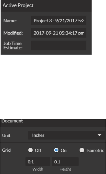
Active Window Info
This window displays information regarding the active project.
Document Window
Active Project Name: Displays name of active project.
Modied:Displayslastdateprojectwasmodied.
Job Time Estimate: Displays estimated time until job is complete.
Unit: Choose unit of measurement from the following -
Pixels: Sets unit of measurement to pixels.
Centimeters: Sets unit of measurement to centimeters.
Millimeters: Sets unit of measurement to millimeters.
Inches: Sets unit of measurement to inches.
Picas: Sets unit of measurement to picas.
Points: Sets unit of measurement to points.
Grid: Toggles grid on/off/isometric.
On: When “on” grid displays in workspace.
Off: When off, grid does not display in workspace.
Isometric: Toggles grid from squares to isometric grid.
Width: Displays width of item according to chosen unit of measurement.
Height: Displays height of item according to chosen unit of measurement.
13

Hide Window: Click to hide vector engraving parameters window.
Show All Parameters: Toggle to show or hide all parameters.
Change Position: Drag with mouse to reorder any color.
Color Indicator: Separates vector cuts with color indicators.
Speed: Input speed settings.
Power: Input power settings.
Current: Input current settings.
Passes: Input the number of passes for the laser.
Window appears when vector le is detected and is used to input vector settings.
Vector Engraving Parameters Window
14
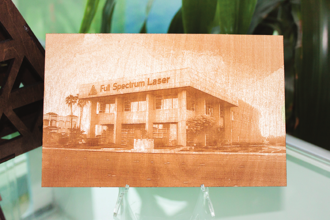
Indicators (Bottom Row)
Position Indicator: Displays current position of the laser on the grid.
Time Remaining Indicator: Displays the time remaining to complete the current job.
Status Indicator: Displays whether laser is ready to initiate a job or is currently executing a job.
Sync Indicator:
Machine Indicators: Displays information on connected devices.
Device Connection Available:
Lid Indicator: Tells operator if lid is open or closed.
Water Flow Indicator:Tellsoperatorifwaterisflowingthroughthelasertubeornot.
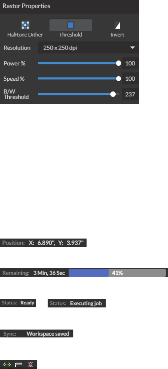
Raster Properties Window
Halftone Dither: Apply Halftone Dither.
Threshold: Apply Threshold.
Blur:Adjustblurlterradiusfrom0to30.
Edge: Adjust edge enhancement threshold from 0 to 30.
Intensity: Adjust intensity from -255 to 255.
Invert: Reverse Black and White elements.
Resolution: Set resolution (250, 500, 1000 dpi).
Poser %: Select power percentage from 1 to 100.
Speed%: Select speed percentage from 1 to 100.
B/W Threshold: Select black and white threshold from 0 to 255.
15

What is Vector Cutting?
Vector cutting is the most common feature of a laser cutter. Vector cutting with a laser means “to cut
a line or shape”. When vector cutting, the laser follows the “vector lines” embedding in the vector
image to cut out the design. The laser starts at a designated location and follows the vector lines
until the shape is cut out. This process is highly accurate and requires no resolution adjustments
because of the properties of a vector image.
Vector Images
In Vector Cut mode, the software receives information from the print stream and interprets it as a
seriesofpathsforthelaserheadtofollow.Fortheprintstreamtohavevectorinformation,thele
beingprintedmustbeavectorimage.Vectorimagesaremoreflexiblethanrasterimages.These
images are created using mathematical equations rather than pixel blocks. PDF’s work great as
vectorlesandareeasytoresizewithoutlosingresolution.Companylogosandbrandedgraphics
are usually vector images.
What is Engraving?
Engraving is the process by which complex designs are etched into a workpiece. Engraving
can range from a simple surface mark all the way through deep material removal. Engraving is
differentiated from cutting in that cutting is the process of burning a closed contour completely
through a workpiece. Engraving is also known as “Raster Engraving” or “Rastering”. For engraving,
a laser has two states: on and off. Every black pixel or “laser dot” is the result of the laser turning on
andringatthatlocation.Thislocationiscontrolledbytheinputimage,whichcanbethoughtofas
a“map”ofonandoffpixels.Thelaserresindividualpulsescorrespondingtopixelsinanimage.
When the laser is operating in raster mode the head moves rapidly from left to right and slowly from
top to bottom, engraving your image pixel by pixel and line by line.
USER OPERATIONS
This section will guide you through using your Muse laser cutter. To get started, it is important to
understandthemeaningsof“VectorCutting”and“RasterEngraving”andtheirassociatedletypes.
RASTER
Project Examples
File Types
Preferred File Type
File Composition
VECTOR
PDF, SVG
Signs, Logos, Parts, Gears
PDF
Geometric Formulas
JPEG, GIF, PNG, TIF
Image Engraving, Surface Marking
JPEG
Pixels
16
Images and Engraving
Engravable images use multiple colored pixels to form an image. JPEGs and PNGs are common
engraving image types. Most of the photos found on the Internet and photo prints are raster images.
Rasterimagesarecreatedusingaxednumberofcoloredpixels,sotheycan’tbedramatically
resized without distorting their resolution. When sized to ft a space they weren’t designed to,
the pixels become visibly grainy and the image becomes distorted. When this happens, altered
photos may appear pixelated or low resolution compared to the original source. Because of this,
itisimportantthatyousaverasterlesatpreciselythedimensionsneededtoeliminatepossible
resolution issues.
PDF Files
Engravingworkswithbothvectorandpixel-basedsourceles,allowingyoutoengraveanything
fromasimpleblocklogoallthewaytohigh-resolutionphotographs.APDFletypeisgenerally
treatedasvectorle,however,RetinaEngrave3.0canreadPDFlesaseitheravectororan
engravinglewhenyouimporttheimage.Thisallowsoperatorgreatfreedominconvertingany
imageletoaPDF.
Direct Printing PDF Files
TheeasiestwaytoimportanyletypetoRetinaEngrave3.0isto“drag‘ndrop”itdirectlyintothe
workspacewindow.Ifthereareeveranyproblemsimportinglesinthismanner,directprinting
aconvertedPDFleisthenextmethodtotry.Mostdesignsoftwarehaveasimplemethodfor
convertinglestoPDFandthendirectlyprintingthemtotheRetinaEngrave3.0software.
Designing in RetinaEngrave 3.0
RetinaEngrave 3.0 includes a robust set of design tools, allowing users to design in the software
without needing outside design software. Third party design software, however, is still an option for
RetinaEngrave 3.0 users. Just about any design software will work (You can choose the software
youaremostcomfortablewith,aslongasyoucanconvertlestoPDF(whichmostcan).Youcan
also “direct print” to the software. Each operating system does this in a slightly different way, so
check the instructions for your particular program.
If you use third party design software and run into a problem with the print interface, we recommend
printingtotheXPSDocumentImageWriterorsavingasaPDF.PDFlessavevectorinformation
and are the best way to carry artwork from a non-compatible operating system (Mac or Linux) onto
your Windows PC.
Compatible design packages include: CorelDraw, Adobe Illustrator, Inkscape and Google’s free
online vector drawing application. Additionally, most CAD packages are able to output drawings in
a vector format for printing; Autodesk 123D is particularly interesting for its cost (free) and built-in 3D
slicing capabilities.
17

USING YOUR LASER CUTTER
Project Workflow
The RetinaEngrave 3.0 software works with your FSL Laser Cutter to create a simple and
intuitivesetofoperationsthatiseasytolearnanduse.Withexperience,youwillndyour
machineachievingamazingresultsfollowingthisprocedure.UsethisProjectWorkflowList
for the “best practice” sequence for any project and follow the step-by-step instructions
fromstarttonish.
Project Workflow Checklist
0. Safety First
Before starting any project, be sure you are aware of all safety issues. Be sure you read
and understand all safety warnings presented in Section I: Safety First and that all safety
requirements are being upheld. This is a good time to check your machine’s power
connections and that the accessories are properly attached and are operating normally.
1. Create Design
Typically, projects are created in design software and then imported to RetinaEngrave 3.0.
Generally,aPDFleisoptimalformostvectorcuts,asPDFlesareeasytoconverttoand
most design software has “convert to PDF” as a standard feature. For rastering (engraving),
aJPEGleisbestasthesearebitmaplesperfectforpixelbasedimages.Itisimportant
to know, at this stage, if you intend to do a vector cut or an engraving and choose the
mostappropriateletype(PDForJPEG).Thiswillgreatlyaidthesoftwaretorunthejob
smoothly and quickly. RetinaEngrave 3.0 includes a robust set of design tools, allowing
users to design in the software without needing outside design software. Third party design
software, however, is still an option for RetinaEngrave 3.0 users. Just about any design
software will work (You can choose the software you are most comfortable with, as long as
youcanconvertlestoPDF(whichmostcan).Youcanalso“directprint”tothesoftware.
Each operating system does this in a slightly different way, so check the instructions for
your particular computer.
Vector File
Geometric based
image. Example: PDF
Raster Image (bitmap)
Pixel based image.
Example: JPEG
18

2. Connect to RetinaEngrave 3.0
Follow the instructions presented in Section III: Installation & Assembly. As a recap, you
willturnonyourcomputerandyourlasercutterandwaitforbothtonishtheirbootcycle.
Then, using the touch screen, touch the “Settings” button and then touch “Network”. Copy
the IP address on the touch screen into your computer’s browser and the program will
appear, ready to use. For best results, we recommend using Google Chrome as this is the
most compatible with
RetinaEngrave 3.0 technology.
3. Import Design
Import your designs by selecting the “Open File” icon, or by dragging and dropping your
leintotheworkspace.Thissoftwaredetectsawidevarietyofletypes,however,forvector
cutsPDFlesworkbestandaresimpletoconvertonmostdesignsoftware.Forraster
engraving,theJPEGleformatiswidelyusedandcaneasilybetakenfromacellphone
photooranimagefoundonline.Itisimportanttoknowwhatlesworkbestwithvectoror
raster images. A raster image is a pixel based image (bitmap) and works well as a JPEG
le.WhenyouimportaJPEGle,thesoftwarewillautomaticallydetectitasarasterleand
will setup the project accordingly by presented raster options in the properties tab menu.
4. Place Material
At this stage you will place your material into the laser bed workspace. The material can be
placed anywhere within the workbed, however, we recommend placing material close to
center. Once the material is placed, close the lid. Your material is what you will be cutting
or engraving. Typical materials include wood, acrylic, cardboard, fabric, etc. Note that is
the user’s responsibility to know the components of any material used and the limitations
of utilizing that material (thickness, chemical residues, etc.) with a 45W laser tube. Always
check with the material manufacturer, or MSDSonline.com, if there are any questions to its
usage. We recommend using a Materials Log to keep track of the different materials you
use.
5. Focus
Follow the focusing instructions given in your machine’s user manual. Note that if your
machine has an auto-focus feature, focusing will be done automatically when the job is run.
6. Align Laser to Material
Alignment of the material ensures the design to be cut is contained within the material in the
workspace. This process also makes sure the design is aligned to the material so the cut is
positioned straight. Typically this can be done with a simple vision check while “jogging
the perimeter”.
By using the directional arrows on the touchscreen or the arrow keys on your computer,
move the laser dot to the top left corner of your material. When placing an engraving
image, leave at least ½” inch of space on the left and right side. When creating engravings,
you must compensate for the left and right overshooting of the laser head. Once the
material looks aligned, click the “Jog Perimeter” button. The laser head will automatically
outline the material with the red beam diode. You can then adjust the material as needed.
Note the laser head will continue to outline the material until stopped manually by clicking
the “Run Perimeter” button a second time. See Positioning below for
more options.
19

7. Adjust Object Properties
Itisagainimportanttoknowifyouintendtoraster,vectorcutorboth.Oncetheleis
imported, and the image is clicked with your mouse, you will have access to the Properties
Tab. Click this tab and select the parameters for your cuts and/or engravings. For details on
setting these parameters,
see below.
8. Run Job
Clicking the “Start Job/Play” button begins the laser cutting process. Before doing so,
double check your safety protocol and that your system accessories are connected
properly.Besuretomonitorthejobwhilethelaserisring.
20

Engraving
Engraving, also called Rastering, is the process of creating a surface image on material without
cutting through the material entirely.
Setting Engraving Properties
Clicking an object (design image) in the workspace will allow you to access that object properties
tab. The software will identify if the object is a vector or an engravable object and present the
appropriate properties window. To show the properties of an engravable object, click the object.
Setting Resolution
The resolution of your engravings can be controlled by the DPI (Dots Per Inch). DPI options include
250, 500, and 1000. The more dots per inch, the higher precision and quality of your images, while a
lower DPI will process and engrave faster.
Remember that with a higher DPI (1000), the laser is in contact with the material for a longer period
of time and may result in deeper engravings than with a lower DPI (250). Speed and power should
be compensated for different DPI settings. The software’s default resolution is set to 250 DPI.
21
Setting Raster Power
The power settings determine the output of the laser tube. A 100% power setting will create
a deeper engraving while lower settings will create more surface level engravings.
Setting Raster Speed
Speed settings determine how quickly the laser head will move. For faster engravings,
100% is ideal. Lowering the speed will allow you to create deeper engravings, as it allows the laser
beam to be in contact with the material for a longer period of time.
Applying B/W Threshold
At this moment, the image is still displayed in black and white. The black and white raster feature is
great for tracing logos, text, or simple high contrast images that only appear in a single color. You
can adjust the threshold of what’s considered black, and what’s considered white by selecting your
image and clicking “Threshold”. This will bring up a B/W Threshold slide bar, from which you can
adjust B/W threshold to your liking.
3D Engraving Options
For images that have shadows and depth, it’s ideal to use 3D engraving “also called dithering”.
Dithering creates a series of dots similar to newsprint. This effectively creates a grayscale that is
ideal for photorealistic engravings. To dither an object, click the dithering button. You can then
adjust the dither with the Blur, Edge and Intensity slide bars.
22

Vector Cutting
Setting Vector Properties
WhenaPDFleisimportedintoRetinaEngrave3.0,theprogramautomaticallydetectsitasbotha
vectorleandarasterle.
Vector Color
Tags allow you to create separate vector layers and keep track of them with a unique color. Each
color will match an object in the workscreen. You can set the order of operations by clicking on the
“three dots” and then dragging the layer up or down. Objects are then processed from top
to bottom.
23

Vector Engraving Parameters Window
Windowappearswhenvectorleisdetectedandisusedtoinputvectorsettings.
Hide Window: Click to hide vector engraving parameters window.
Show All Parameters: Toggle to show or hide all parameters.
Change Position: Drag with mouse to reorder any color.
Color Indicator: Separates vector cuts with color indicators.
Speed: Input speed settings.
Power: Input power settings.
Current: Input current settings.
Passes: Input the number of passes for the laser.
24
Setting Vector Speed
The optimal speed setting varies, depending on the power of the laser tube and properties of the
material itself. Like raster engraving, speed will determine how quickly the laser head moves. You
willneedtoexperimentwithmaterialtestingtondtherightspeedforyourvectorcuts.
Setting Vector Power
Power will determine how much power the laser tube delivers. As with speed, power will vary
depending on the wattage of the laser tube and the material itself. You will need to experiment with
materialtestingtondtherightspeedforyourvectorcuts.
Setting Vector Current
Vectorcurrentisacontroluniquetovectorles.Vectorcurrentcontrolsthepulseofthelaser.100%
will create constant power for smooth cutting, while lower percentages will add increasingly more off
time between pulses. As always, settings will vary with your tube wattage and type of material. It’s
besttotestonaninconspicuouspartofyourmaterialbeforecreatingyournalpiece.Onceoptimal
results are discovered for speed, power and current, through material testing, record the settings for
each in a materials log.
Passes
This allows the operator to assign how many times the laser will complete a full cycle. Adding
passes creates deeper cuts. Note that if you delete a vector line (by clicking “-“), set passes
to“0”rst.
Show All Parameters
This toggle switch displays or hides all possible vector tag as a series of color options. Often when
performing both vector cuts and raster engraving, it is a good idea to change the color of the vector
cut to something other than black. This will avoid the laser detecting the vector cut as part of
the raster.
25

Basic Vector Cutting Example
In the software, the red lines tell the laser what to cut. All red lines will be cut through the material
creatingtheemptyspaceinthenalproject.
Vector Cutting Example
Wecanoutline(asopposedtoll)partsofthepatternforaseconddesignoption.Again,wewill
instruct the laser using our vector properties In this design, the blue lines will not be cut through on
our material, but instead will be marked, as the red outline still cuts.
Combining Vector and Raster
Engravings can be combined with vector cuts to create a variety of outcomes. A simple example
is to engrave an image, and then cut the image out with a vector outline. In this case the laser will
rasterintheblackfllandcuttheredline.
26

DESIGNING WITH RETINAENGRAVE 3
RetinaEngrave 3.0 contains design tools to allow for custom designs within the software itself. Here
you can design and create objects without accessing third-party design software.
Adding Text
Click the “T” icon and then click anywhere in the view window. You can now write your text. To
customize your text, click on the text object you created and a new window will appear with options
to adjust the positioning, size and font of your text.
Full Text Options Window
27

Text Positioning
Text position can be quickly adjusted by clicking on one of the following options.
Text Positioning Coordinates
This window displays the coordinates and other specs of the selected text. Coordinates can be
changedmanuallybyenteringthedesiredspecicsdirectlyintothesoftware.
Distribute Horizontally: Evenly arrange selected Text horizontally.
Distribute Vertically: Evenly arrange selected text vertically.
Align Left: Align text to the left.
Align Center: Align text to center.
Align Right: Align text to right.
Align Top: Align text to top.
Align Middle: Align text to middle.
Align Bottom: Align text to bottom
Position: Displays position of text in X/Y coordinates in the workspace. Click box to directly input
X/Y coordinates.
Size: Displays size of text according to width and height. Click box to directly input desired width
and height of text.
Angle: Displays angle of text as a degree. Click box to directly input angle degree of text.
Transform: Clicking the transform button brings up the Transform Window options.
28

Text Transform Options
Transform options allow the operator to alter the shape and skew of text.
Text Appearance
Move: Set X/Y coordinates.
Scale: Manipulate the scale of text, separately, in width and height.
Rotate: Rotate text a set number of degrees, up or down.
Skew: Skew the angle of text by a set number of degrees on the X and Y axis.
Copies: Create duplicates of the selected text.
Apply: Click to apply all transform changes.
Select Font: Choose or change selected text font.
Weight: Choose bold and italic options for selected text.
Font Size: Choose font size for selected text.
Alignment: Align or justify selected text left, right or center.
Spacing: Set pacing or characters, word blocks and line spacing.
Sizing: Lock all sizing options (Fixed) or allow custom alterations (Auto).
When set to auto, click on text and use mouse to manipulate corner nods to change size.
29
Text Path Options
Attach Text to Path
This function allows the user to attach text to a shape and contour the text to that shape. As an
example, user creates an ellipse design and a text element separately. With the mouse, drag a
square over both. By clicking Attach Text to Path, the text is merged with the ellipse and the text
conforms to the contour of the shape. The user can then drag the text element to the desired
position, using the mouse.
Detach Text from Path
This function reverses the Attach Text to Path option. Select the object and text with the mouse by
dragging a square to highlight both. Then, click Detach Text from Path. The shape and the text will
now be separated.
Convert to Path (Shift+Ctrl+P)
Convert a non path to a layer path. If a layer is composed of elements that are treated like paths,
internally, or the layer is a Text object, the existing paths that make up the object are simply
extractedfromtheobjectastheyarealreadydened.Theresultisacompoundpathcontaining
all of the separate paths. Any transform information from the original layer is not retained in the
individual paths. For all other types of layers a new path is created, preserving any transforms. The
user creates a text layer then converts to a path. Because the text was comprised of more than one
distinct element a compound path is created. The compound path can then be split into separate
paths for each distinct element in the text.
Convert to Raw Path
Convert a path or non path layer to a new path. This is similar to Convert to Path with some important
differences. With Convert to Raw Path new path objects are always created regardless of the type
of the original layer and transforms are preserved. The user creates a text layer then attaches it to
an ellipse path so that it follows the curvature of the ellipse, then converts the text to a raw path. The
text retains its curvature because the transforms of the separate text paths are preserved.
30
Creating Objects in RetinaEngrave 3
The easiest way to create an object is to select a shape from the tools menu. For example, you want
to make a circle. Select the circle tool, then click and drag to create a circular shape. By holding
shift while dragging, you can constrain the proportions so that the circle is perfectly round. Design
view has hundreds of shapes that can be selected and manipulated to endless choices. Click the
“Shape” icon to access shape library.
Click the Square Icon and then click and hold anywhere in the view window. By moving the mouse,
you can expand and manipulate the square you want to create. By clicking the drop down arrow
next to the Square Icon, you can choose other base shapes and expand them just like with a
square. The basic shape library includes line, rectangle, ellipse, polygon, triangle and star. You
can modify any shape by clicking on it and then adjusting the interface data appearing on the right
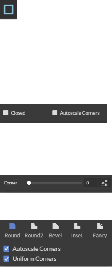
side of the screen. Each shape will have slightly different options as follows:
Closed:
Autoscale Corners:
Corner: Slide bar contorts and manipulates corner styles.
Advanced Settings: Open a window for additional corner options.
Round: Create rounded corners.
Round2: Create inverted rounded corners.
Bevel: Create beveled corners.
Inset: Create inset corners.
Fancy: Create fancy corners
Autoscale Corners: Toggle autoscale corners on and off.
Uniform Corners: Click to ensure all corners have the same parameters.
Creating Shapes
Line (L)
Rectangle (R)
31

Angles: Input custom angles
Shape
Open: Click for open ellipse..
Closed: Click for closed ellipse.
Pie: Click for pie shaped ellipse.
Points: Slide bar to create polygons with multipoints (3 to 25).
Corner: Slide bar to curve corners
Advanced Settings: Clicking the icon opens a new popup window.
Round: Create rounded corners.
Round2: Create inverted rounded corners.
Bevel: Create beveled corners.
Inset: Create inset corners.
Fancy: Create fancy corners
Autoscale Corners: Toggle autoscale corners on and off.
Uniform Corners: Click to ensure all corners have the same parameters.
Plain Edges:Toggle plain edges on and off.
Corners: Input outside and inside corner curvature.
Radius: Input outside and inside corner radius.
Angles: Input outside and inside corner angles.
Ellipse (E)
Triangle, Polygon & Star
Advanced Settings
32
Creating and Manipulating Compound Shapes & Objects
Operators can combine and modify shapes and objects to create unique compound shapes and
objects with these functions (see also Modify):
Split Selection (Shift+Ctrl+G)
Split up a previously created compound shape or object that has been Unioned with other shapes.
Select the compound shape and choose Split Selection. The different objects are split back up into
individual layers that can be moved independently.
Create Compound Shape->Union
Combine multiple layers into a single compound layer. Union will create a compound shape contain-
ing all of the selected layers, retaining their relative positions. Union together several different ob-
ject and create a compound shape so they can all be moved and manipulated as one. To reverse,,
select the compound shape and choose Split Selection. The different objects are split back up into
individual layers so you can move one of them independently.
Create Compound Shape->Intersection
Combine overlapping layers into a single compound layer. Intersection will create a compound
shape containing the areas where the selected layers overlap. Intersect together part of an ellipse
and part of a rectangle to create a new compound shape with curved and straight lines.
Create Compound Shape->Subtract
Remove and combine non-overlapping layers into a single compound layer. Subtract will create a
compound shape containing only the areas of the last selected layer where the other selected layers
do not overlap. For example, users can create an ellipse and subtract a rectangular area so the
ellipse can be placed over another layer and not obstruct part of it. Or use to make a design that is
made up of standard shapes by subtracting certain areas.
Create Compound Shape->Difference
Combine non-overlapping layers into a single compound layer. Difference is the opposite of Inter-
section. It will create a compound shape containing only the areas where the layers do not overlap.
For example, the user can create a large circle ellipse, then create a smaller circle ellipse. Place the
smaller circle ellipse over the large circle ellipse and center it. Select both layers and choose Differ-
ence. A hole is created in the large circle ellipse and a donut design is formed.
Create Nested Compound
Combine compound shapes into a single compound shape. All of the selected compound shapes
will be nested within the compound shape that was selected last. For example, if user has created
compound shapes and created the layout with the desired spacing but would like to move them all
while retaining the existing layout, creating a nested compound shape that includes them all
works best.
Convert to Outline
Createanoutlinepathofaspeciedsizearoundanobject.Iftheoriginalobjectisnotcontinuous,
such as a line, an outline is created around the line and the original line is replaced. If the original
object is continuous, such as a rectangle, an outline is created around the rectangle and the original
rectangle is preserved, resulting in a compound path with two rectangles. The user creates a curved
line then converts it to an outline of size 10. The result is a continuous curved polygon that looks like
a wet noodle.
33
Expand/Shrink
Scaleanobjectupordownbyaspeciedamount.Theusercreatesanobjectandwantstogrow
itafewpixelsbuttryingtoscaleitwithaselectionboxistoodifcult.Hecanexpandtheobjectby
specifying the exact amount.
Creating & Converting Vector Paths
A vector path indicates the line the laser moves along while cutting. For a simple line, the path is a
clear route from Point A to Point B. More complicated paths, and shapes, can be created using the
following options in the Modify drop-down window:
Vectorize Border
Use to create a vector path of the border of an object. For example, the user creates an object, such
as a rectangle, and wants to have a vector path of just the border of the triangle.
Vectorize Image
Usetocreatevectorpathsofeachseparateelementinanimage.Forexample,theuserrst
imports an image. User then wants certain parts of the image to be vectors so they can be cut. User
vectorizes the image and then moves some of the resulting vectors out of the image object. The
vectors can then be edited.
Join Paths (Ctrl+J)
Combine 2 or more selected paths into one compound path. The result is a single layer titled
‘Compound Path’. It does not connect them into one continuous path but rather a single object with
breaks between the individual paths that were joined. The user joins together multiple path objects
so that they can be transformed more easily and change their properties as a single object.
Split Paths (Shift+Ctrl+J)
Split a compound path into its original separate paths.The result is a path layer for each separate
path in the Compound path.
Simplify Path (Ctrl+Alt+S)
Simplify (and smooth) a path to varying degrees of tolerance. The user creates a freehand line or
compound curve but the resulting curve has some sharp turns and jagged edges. Next, select the
pathandsimpliesitwithatolerance(startwith20%).Theresultingpathhasfewerverticesand
smoother turns.
Connect Path Lines
Connect together the ends of 2 or more paths. The user vectorizes an image containing text. Due
to the low quality of the image some, of the text characters have breaks in their paths, so the user
selects the lonely paths and uses the “Connect Paths Lines” feature to connect the paths.
Break Curve
Breakapartapathataspeciednode.Theusercreatesapathbutwouldliketoseparateitand
add space at certain vertices to add another artistic element in between. Or maybe to specify
different engraving parameters for different parts of the path. To do so, the user selects a node and
chooses “Break Curve”. The path is separated into two separate paths.
Reverse Order
Reverse the order of nodes in a path. When the user creates several paths and uses the “Connect
Paths Lines” feature, they are connected but not at the desired ends. This is because the paths are
connectedfromthelastnodeofonepathtotherstnodeofthenext.Undothepreviousactionand
chooses “Reverse Order” on one of the paths. Then connects the paths and they are
connected perfectly.
34
OTHER OPERATIONS
Positioning the Laser Head (Jog)
Operators will want to become accustomed to moving the laser head, in order to position the laser.
This can be done in one of two methods: manual and jog control. Manually moving the laser head
requires that the laser head be in the “Unlocked” position. To unlock the laser head, push the “Lock”
icon, on the touch screen, so that the icon has an open lock icon. The laser head can now be freely
moved to any position in the workspace by hand.
Jogging is when the operator uses the touch screen “jog” buttons, or the arrow keys on your
keyboard, to move the laser head. To use the jog feature, the laser head must be in the “Locked”
position. To lock the laser head, push the “Lock” icon so that the icon has a closed lock icon. Now
you can use the directional arrows to move the laser head to any position in the workspace.
Positioning Material
Relative positioning is relative to the laser head. The red dot from the laser will be considered
the top left corner of an image. This makes positioning easier without the use of the
Muse camera system.
Absolute positioning is the default mode and will directly translate the object’s location on the
computer workspace to the respective location on the laser bed. Absolute positioning is ideal when
using the
camera system.
You can switch from Relative Positioning to Absolute Positioning by going to Settings, within the Edit
drop-down options. Click Settings>Device. Next, choose Absolute Positioning or Relative Positioning
on the slide bar across from Laser Positioning. Click “Save Changes” when you are done
35

Mouse Controls
A. Drag ‘n Drop
Clickandholdadesignleandthendragitintotheworkspace.Youwillbeinvitedto“Drop
anywhere!”. Once uploaded, click and hold the left mouse button and drag the mouse to move the
object in the workspace.
B. Resize / Rotate
Clicking on the object with your mouse will highlight the square adjusters for size and orientation.
Use the mouse to manipulate the object’s size by expanding or constricting the square adjusters or
turning the rotation node to rotate object.
C. Alt + Left Click to Rotate
Hold the Alt button on your keyboard, then left click and hold your mouse over the rotation node. By
moving the mouse, you can resize the object from center rather than the corner.
D. Alt + Left Click to Resize
Hold the Alt button on your keyboard, then left click and hold your mouse over one of the four corner
“resizing” nodes. By moving the mouse, you can to rotate the object from the opposing node.
E. Home to Location
Instantly home the laser to any location in the work bed by simultaneously holding the Ctrl key and
left-clicking the mouse. This allows you to choose where the laser starts the job.
Resize Rotate Home to Location
36

Camera: Capture Workspace
Use the onboard camera to capture your workspace to align your design.
1. Place material in center of laser bed.
2. Position the laser head above the material and use the focus billet to focus the cone above the
material surface. Ensure your material does not impede the movement of the laser head.
3. Initiate Camera Sequence - Press the Camera Icon on your RE2 software, or on the LCD touch
screen (for touch screen controls, see user manual) - Note that you 1) use the camera button, 2)
position the head, and 3) press the camera button again (this initiates sequence with no indication on
software). Follow the steps on the screen. Click “New Height Measurement”. The laser head will shift
back and measure the height of your material using the secondary red beam laser. You can repeat
this step several times for more accurate results. If results don’t improve, it may be that your material
is an uneven surface. Click Continue when focused.
4. After 9 photos are taken and stitched, your workspace should now represent your laser bed.
Position your design as needed (for help importing, see the Work-Flow Section), and adjust setting.
5. You are now ready to run your job! To double check a position on your workspace, CTRL-Click
anywhere on the work space to position the laser head there.
37

Camera:Vector Trace
Use the onboard camera to capture your workspace to align your design.
1. Choose your material, and prep. Flat objects work best, and we suggest you place masking tape
(paper tape) on the surface before marking with a pen (sharpie). Don’t allow the masking to tape to
overlay on the material when applying more than one strip.
2. Using a thick black marker or pen, draw on your material. Thick solid lines will be read the best. If
coloring in a space, ensure completely lled in.
3. Capture the workspace as shown in steps 3 & 4 in the “Capture Workspace” instructions.
4. Click on the “Vectorize” icon in the top menu bar (show with label). This will bring up a sub-menu.
Using your mouse, select the section you want to vectorize and press ok. You can repeat this step
as many times as you like. Place a white piece of paper behind your self-drawn design to help aid if
having trouble capturing the area you want to vectorize.
5. You now have Bitmap and Vector data for your object available.
They should appear in the Object Manager box. Delete data not needed. If just engraving, delete
vector data, if just cutting or marking, delete bitmap data.
6. You are now ready to run your job!
MASKING TAPE OVER WORK AREA
Tape
38
