
final page size: 8.5 x 5.5 in CRAFTSMAN
9" (228 MM) BAND SAW
9" (228 MM) SIERRA DE CINTA PARA BRANCO
CMXEBAR600
IF YOU HAVE QUESTIONS OR COMMENTS, CONTACT US.
SI TIENE DUDAS O COMENTARIOS, CONTÁCTENOS.
1-888-331-4569 WWW.CRAFTSMAN.COM
INSTRUCTION MANUAL | MANUAL DE INSTRUCTIONES

English (original instructions) 1
Español (traducido de las instrucciones originales) 25

3
ENGLISH
COMPONENTS
1
Blade tension knob
2
Upper blade wheel
3
Upper cover lock knob
4
Blade guide height
adjustment knob
5
Blade guard
6
Upper blade guide
7
Miter gauge
8
Table aligning bolt
9
Lower blade guide
10
Lower cover lock knob
11
Lower blade wheel
12
Lower wheel cover
Fig. A
13
Wheel brush
14
ON/OFF switch
15
Upper wheel cover
16
Blade tracking knob
17
Power cord
18
Motor
19
Table lock handle
20
Sawdust port
21
Table tilt adjustment knob
22
Table tilt scale
23
Table
24
Blade
25
Upper guide lock knob
Definitions: Safety Alert Symbols and Words
This instruction manual uses the following safety alert symbols and words to alert you to hazardous situations and your risk
of personal injury or property damage.
DANGER: Indicates an imminently hazardous situation which, if not avoided, will result in death or seriousinjury.
WARNING: Indicates a potentially hazardous situation which, if not avoided, could result in death or seriousinjury.
CAUTION: Indicates a potentially hazardous situation which, if not avoided, may result in minor or moderateinjury.
(Used without word) Indicates a safety related message.
NOTICE: Indicates a practice not related to personal injury which, if not avoided, may result in propertydamage.
WARNING: Read all safety warnings and all
instructions. Failure to follow the warnings and
instructions may result in electric shock, fire and/or
seriousinjury.
WARNING: Never modify the product or any part of it.
Damage or personal injury couldresult.
WARNING: To reduce the risk of injury, read the
instructionmanual.
If you have any questions or comments about this
product, call CRAFTSMAN toll free at: 1-888-331-4569.
1
2
3
4
5
6
7
8
9
10
11
12
13
14
15
16
17
18
19
20
21
22
23
24
25

ENGLISH
4
9" (228 MM) BAND SAW
CMXEBAR600
GENERAL POWER TOOL SAFETY
WARNINGS
WARNING: Read all safety warnings,
instructions, illustrations and specifications
provided with this power tool. Failure to follow all
instructions listed below may result in electric shock,
fire and/or seriousinjury.
SAVE ALL WARNINGS AND
INSTRUCTIONS FOR FUTURE
REFERENCE
The term “power tool” in the warnings refers to your mains-
operated (corded) power tool or battery-operated (cordless)
powertool.
1) Work Area Safety
a ) Keep work area clean and well lit. Cluttered or dark
areas inviteaccidents.
b ) Do not operate power tools in explosive
atmospheres, such as in the presence of
flammable liquids, gases or dust. Power tools
create sparks which may ignite the dust orfumes.
c ) Keep children and bystanders away while
operating a power tool. Distractions can cause you
to losecontrol.
2) Electrical Safety
a ) Power tool plugs must match the outlet. Never
modify the plug in any way. Do not use any
adapter plugs with earthed (grounded) power
tools. Unmodified plugs and matching outlets will
reduce risk of electricshock.
b ) Avoid body contact with earthed or grounded
surfaces such as pipes, radiators, ranges and
refrigerators. There is an increased risk of electric
shock if your body is earthed orgrounded.
c ) Do not expose power tools to rain or wet
conditions. Water entering a power tool will increase
the risk of electricshock.
d ) Do not abuse the cord. Never use the cord for
carrying, pulling or unplugging the power tool.
Keep cord away from heat, oil, sharp edges or
moving parts. Damaged or entangled cords increase
the risk of electricshock.
e ) When operating a power tool outdoors, use an
extension cord suitable for outdoor use. Use of
a cord suitable for outdoor use reduces the risk of
electricshock.
f ) If operating a power tool in a damp location
is unavoidable, use a ground fault circuit
interrupter (GFCI) protected supply. Use of a GFCI
reduces the risk of electricshock.
3) Personal Safety
a ) Stay alert, watch what you are doing and use
common sense when operating a power tool. Do
not use a power tool while you are tired or under
the influence of drugs, alcohol or medication. A
moment of inattention while operating power tools
may result in serious personalinjury.
b ) Use personal protective equipment. Always wear
eye protection. Protective equipment such as dust
mask, non-skid safety shoes, hard hat, or hearing
protection used for appropriate conditions will reduce
personalinjuries.
c ) Prevent unintentional starting. Ensure the
switch is in the off position before connecting to
power source and/or battery pack, picking up or
carrying the tool. Carrying power tools with your
finger on the switch or energizing power tools that
have the switch on invitesaccidents.
d ) Remove any adjusting key or wrench before
turning the power tool on. A wrench or a key left
attached to a rotating part of the power tool may
result in personalinjury.
e ) Do not overreach. Keep proper footing and
balance at all times. This enables better control of
the power tool in unexpectedsituations.
f ) Dress properly. Do not wear loose clothing or
jewelry. Keep your hair, clothing and gloves
away from moving parts. Loose clothes, jewelry or
long hair can be caught in movingparts.
g ) If devices are provided for the connection of dust
extraction and collection facilities, ensure these
are connected and properly used. Use of dust
collection can reduce dust-relatedhazards.
h ) Do not let familiarity gained from frequent use
of tools allow you to become complacent and
ignore tool safety principles. A careless action can
cause severe injury within a fraction of a second.
4) Power Tool Use and Care
a ) Do not force the power tool. Use the correct
power tool for your application. The correct power
tool will do the job better and safer at the rate for
which it wasdesigned.
b ) Do not use the power tool if the switch does not
turn it on and off. Any power tool that cannot be
controlled with the switch is dangerous and must
berepaired.
c ) Disconnect the plug from the power source and/
or remove the battery, pack if detachable, from
the power tool before making any adjustments,
changing accessories, or storing power tools.
Such preventive safety measures reduce the risk of
starting the power toolaccidentally.

5
ENGLISH
d ) Store idle power tools out of the reach of children
and do not allow persons unfamiliar with the
power tool or these instructions to operate the
power tool. Power tools are dangerous in the hands
of untrainedusers.
e ) Maintain power tools and accessories. Check
for misalignment or binding of moving parts,
breakage of parts and any other condition
that may affect the power tool’s operation. If
damaged, have the power tool repaired before
use. Many accidents are caused by poorly maintained
powertools.
f ) Keep cutting tools sharp and clean. Properly
maintained cutting tools with sharp cutting edges are
less likely to bind and are easier tocontrol.
g ) Use the power tool, accessories and tool bits, etc.
in accordance with these instructions, taking
into account the working conditions and the
work to be performed. Use of the power tool for
operations different from those intended could result
in a hazardoussituation.
h ) Keep handles and grasping surfaces dry, clean
and free from oil and grease. Slippery handles and
grasping surfaces do not allow for safe handling and
control of the tool in unexpected situations.
5) Service
a ) Have your power tool serviced by a qualified
repair person using only identical replacement
parts. This will ensure that the safety of the
power tool is maintained.
• Plan intricate and small work carefully to avoid pinching
the blade. Avoid awkward operation and hand positions
to prevent accidental contact with the blade.
• Small pieces should be secured with jigs or fixtures. Do
not hold pieces that are so small your fingers are under the
blade guard.
• Support round work properly (with a V-block or clamped
to the miter gauge) to prevent it from rolling and the blade
from biting.
• Cut only one workpiece at a time. Make sure the table is
clear of everything except the workpiece and guides before
turning the saw on.
• Always watch the saw run before each use. If there is
excessive vibration or unusual noise, stop immediately.
Turn the saw off. Unplug immediately. Do not start the
saw again until the problem has been identified and
corrected.
• To free any jammed material, turn the switch off. Remove
the switch key and unplug the saw. Wait for all moving
parts to stop before removing jammed material.
• Do not leave the work area until all moving parts are
stopped. To childproof the workshop, shut off power to
master switches and remove the switch key from the band
saw. Store it in a safe place, away from children.
WARNING: For your own safety, read the entire
Instruction Manual before using the band saw.
• Wear eye protection.
• Do not wear gloves, neckties or loose clothing.
• Make sure the saw is on a firm level surface and properly
secured.
• Use only the recommended accessories.
• Use extra caution with very large, very small or awkward
workpieces.
• Keep hands away from the blade at all times to prevent
accidental injury.
• Do not remove jammed or cutoff pieces until the blade
has stopped.
• Maintain proper adjustment of blade tension, blade
guides and thrust bearings.
• Hold the workpiece firmly against the table.
• Adjust the upper guide to clear the workpiece.
PROPOSITION 65 WARNING
WARNING: Drilling, sawing, sanding or machining
wood products can expose you to wood dust, a
substance known to the State of California to cause
cancer. Avoid inhaling wood dust or use a dust mask
or other safeguards for personal protection. For more
information go to: www.P65Warnings.ca.gov/wood
Some examples of these chemicals are:
• Lead from lead-based paints,
• Crystalline silica from bricks and cement and other
masonry products, and
• Arsenic and chromium from chemically-treated
lumber.
SAFETY INSTRUCTIONS FOR BAND SAW
• To avoid injury from unexpected movement, make sure
the saw is on a firm, level surface and properly secured
to prevent rocking. Make sure there is adequate space for
operating. Bolt the saw to a support surface to prevent
slipping, walking or sliding during operation.
• Unplug and turn the saw off before moving it.
• Use the correct size and style of blade.
• Use blades rated at 2500 FPM or greater.
• Make sure the blade teeth point down and towards the
table when installed on unit.
• Blade guides, support bearings and blade tension
must be properly adjusted to avoid accidental blade
contact and to minimize blade breakage. To maximize
blade support, always adjust the upper blade guide and
blade guard so that it is 1/8 inch (3.2 mm) above the
workpiece.
• Table lock handle should be tight.
• Use extra caution with large, very small or awkward
workpieces.
• Use extra supports to prevent workpieces from sliding
off the table top. Never use another person to support the
workpiece.
• Workpieces must be secured so they do no twist, rock or
slip while being cut.

ENGLISH
6
Your risk from these exposures varies depending on
how often you do this type of work. To reduce your
exposure to these chemicals: work in a well ventilated
area and work with approved safety equipment, such
as those dust masks that are specially designed to
filter out microscopic particles.
Handling the power cord on this product may expose
you to chemicals known to the state of California to
cause cancer and birth defects or other reproductive
harm. Wash hands after handling.
For more information go to: www.P65Warnings.ca.gov
READ INSTRUCTION MANUAL: To reduce the risk of
injury, user and all bystanders must read instruction
manual before using this product.
• Avoid prolonged contact with dust from power
sanding, sawing, grinding, drilling, and other
construction activities. Wear protective clothing and
wash exposed areas with soap and water. Allowing
dust to get into your mouth, eyes, or lay on the skin may
promote absorption of harmfulchemicals.
WARNING: Use of this tool can generate and/or
disperse dust, which may cause serious and
permanent respiratory or other injury. Always use
NIOSH/OSHA approved respiratory protection
appropriate for the dust exposure. Direct particles
away from face andbody.
WARNING: Always wear proper personal hearing
protection that conforms to ANSI S12.6 (S3.19)
during use. Under some conditions and duration
of use, noise from this product may contribute to
hearingloss.
CAUTION: When not in use, place tool on its side on
a stable surface where it will not cause a tripping or
falling hazard. Some tools will stand upright but may
be easily knocked over.
• Air vents often cover moving parts and should be
avoided. Loose clothes, jewelry or long hair can be
caught in movingparts.
ELECTRICAL SPECIFICATIONS AND SAFETY
Power supply and motor specifications
WARNING: To avoid electrical hazards, fire hazards,
or damage to the tool, use proper circuit protection.
Use a separate electrical circuit for your tool. Your saw
is wired at the factory for 120 V operation. Connect to
a 120 V, minimum 10 Amp circuit and use a 10 Amp
time delay fuse or circuit breaker. To avoid shock or
fire, if power cord is worn, cut, or damaged in any
way, have it replaced immediately.
Grounding instructions
WARNING: This tool must be grounded while in use
to protect the operator from electrical shock.
In the event of a malfunction or breakdown, grounding
provides a path of least resistance for electric currents and
reduces the risk of electric shock. This tool is equipped with an
electrical cord that has an equipment-grounding conductor
and a grounding plug. The plug must be plugged into a
matching receptacle that is properly installed and grounded in
accordance with all local codes and ordinances.
Do not modify the plug provided. If it will not fit the
receptacle, have the proper receptacle installed by a qualified
electrician.
Improper connection of the equipment grounding conductor
can result in risk of electric shock. The conductor with the green
insulation (with or without yellow stripes) is the equipment
grounding conductor. If repair or replacement of the electrical
cord or plug is necessary, do not connect the equipment
grounding conductor to a live terminal.
Check with a qualified electrician or service person if you do
not completely understand the grounding instructions, or if you
are not certain the tool is properly grounded.
USE only 3-wire extension cords that have three-pronged
grounding plugs with three-pole receptacles that accept
the tool’s plug. Repair or replace damaged or worn cords
immediately.
Use a separate electrical circuit for your tool. This circuit must
not be less than #16 wire and should be protected with a
minimum 10 Amp circuit time lag fuse. Before connecting
the motor to the power line, make sure the switch is in the off
position and the electric current is rated the same as the current
stamped on the motor nameplate. Running at a lower voltage
will damage the motor.
Guidelines for extension cords
Use the proper extension cord. Make sure your extension
cord is in good condition. Use an extension cord heavy enough
to carry the current your product will draw. An undersized
cord will cause a drop in line voltage resulting in loss of power,
overheating and burning out of the motor. The table below
shows the correct size to use depending on cord length and
nameplate ampere rating. If in doubt, use the next heavier
gauge. The smaller the gauge number, the heavier the cord.
Make sure your extension cord is properly wired and in good
condition. Always replace a damaged extension cord or have it
repaired by a qualified technician before using it. Protect your
extension cords from sharp objects, excessive heat and damp or
wet areas.

7
ENGLISH
Minimum Gauge for Extension Cords (AWG)
Volts
Total Length of Cord in Feet
(meters)
120 V 25 (7.6) 50 (15.2) 100 (30.5) 150 (45.7)
240 V 50 (15.2) 100 (30.5) 200 (61.0) 300 (91.4)
Ampere Rating
American Wire Gauge
More
Than
Not
More
Than
0 6 18 16 16 14
6 10 18 16 14 12
10 12 16 16 14 12
12 16 14 12 Not Recommended
WARNING: This tool is for indoor use only. Do not
expose to rain or use in damp locations.
This tool is intended for use on a circuit that has a receptacle
like the one illustrated in Fig. B . Fig. B shows a three-pronged
electrical plug and receptacle that has a grounding conductor.
If a properly grounded receptacle is not available, an adapter
(Fig. C) can be used to temporarily connect this plug to a two-
contact grounded receptacle. The adapter (Fig. C) has a rigid
lug extending from it that MUST be connected to a permanent
earth ground, such as a properly grounded receptacle box.
CAUTION: In all cases, make certain the receptacle is
properly grounded. If you are not sure, have a qualified
electrician check the receptacle.
The label on your tool may include the following symbols. The
symbols and their definitions are asfollows:
V ......................... volts
Hz .......................hertz
min ..................... minutes
or DC ......direct current
...................... Class I Construction
(grounded)
…/min ..............per minute
BPM .................... beats per minute
IPM ..................... impacts per minute
RPM .................... revolutions per
minute
sfpm ................... surface feet per
minute
SPM .................... strokes per minute
OPM .................... oscillations per
minute
A ......................... amperes
W ........................watts
or AC ...........alternating current
or AC/DC .... alternating or
direct current
...................... Class II
Construction
(double insulated)
n
o
.......................no load speed
n .........................rated speed
......................earthing terminal
.....................safety alert symbol
.....................visible radiation
..................... avoid staring at
light
..................... wear respiratory
protection
..................... wear eye
protection
..................... wear hearing
protection
..................... read all
documentation
SAVE THESE INSTRUCTIONS FOR
FUTURE USE
Motor
Be sure your power supply agrees with the nameplate
marking. Voltage decrease of more than 10% will cause loss
of power and overheating. These tools are factory tested; if
this tool does not operate, check power supply.
Fig. B
Fig. C
Three-Pronged Plug
Grounding Prong
Properly Grounded
Three-Pronged Receptacle
Grounding Lug
Make sure this is
connected to a
known ground.
Two-Pronged
Receptacle
Adapter

ENGLISH
8
TOOLS NEEDED FOR ASSEMBLY
CARTON CONTENTS
Unpacking And Checking Contents
Carefully unpack the band saw and all its parts, and
compare against the list below and the illustration. With the
help of an assistant, place the saw on a secure surface and
examine it carefully.
WARNING: To avoid injury from unexpected starting
or electrical shock, do not plug the power cord into
a source of power during unpacking and assembly.
The cord must remain unplugged whenever you are
adjusting/assembling the saw.
WARNING: The saw is heavy and should be lifted with
care. If needed, get the assistance of someone to lift
and move the saw.
WARNING: If any part is missing or damaged, do
not attempt to assemble the band saw, or plug in
the power cord until the missing or damaged part is
correctly replaced.
Table of Loose Parts
Supplied Not supplied
Phillips Screwdriver
Adjustable Wrench
Combination Square
UNPACKING YOUR BAND SAW
A
B
C
D E
Feeler gauge
(size 0.02 in.)
2 mm hex wrench
4 mm hex wrench
Open end wrench
ITEM DESCRIPTION Q’TY
A.
Band saw
1
B.
Instruction manual
1
C.
Miter gauge
1
D.
Hardware bag
Table lock handle
1
washer
1
Open end wrench
1
2 mm hex wrench
1
4 mm hex wrench
1
E.
Band saw table assembly
1

9
ENGLISH
Installing And Removing Blade (Fig. G, H)
WARNING: To avoid injury from accidental
starting, always turn the switch OFF and remove
the plug from the power source before moving,
replacing, or adjusting the blade.
Removing (Fig. G, H)
1. Loosen the blade tension by turning the blade tension
knob
1
counterclockwise. (Fig. G)
2. Open the upper wheel cover
15
and lower wheel
cover
12
by rotating the upper cover lock knob
3
and
lower cover lock knob
10
.
3. Remove the table aligning pad from the table.
4. Loosen the upper guide lock knob
25
on the rear side
of the band saw by turning it counterclockwise. (Fig. H)
5. Lower the upper blade guide
6
to its lowest position by
turning the blade guide height adjustment knob
4
.
6. Pull and open the blade guard
5
as shown in Fig. H.
7. Remove the blade
24
from the upper blade guide
6
and lower blade guide
9
.
8. Carefully pull the blade
24
from the table slot
27
and from the upper blade wheel
2
and lower blade
wheel
11
.
9. Hold the blade
24
, slide it out from the left side blade
guard slot
33
.
WARNING: Many illustrations in this manual
show only portions of the Band Saw. This is
international so that points being made in the
illustrations can be highlighted. Never operate
the saw without all guards securely in place and
in good operating condition.
ASSEMBLY AND ADJUSTMENTS
Estimated Assembly Time: 50 - 60 minutes
WARNING: For your safety, never connect plug to
power source receptacle until all assembly and
adjustment steps are complete, and you have
read and understood the safety instructions.
Installing The Band Saw Table
(Fig. D, E, F)
1. Bag "E" - Loosen the table aligning bolt
8
and remove
the table aligning nut
26
from the table. (Fig. D)
2. Guide the table slot
27
over the saw blade
24
. (Fig. E)
3.
Turn the scale pointer
28
down clockwise and
place
the table by aligning the slot
29
of table tilt scale
22
with two pins
30
, then pull the table tilt adjustment
knob
21
out and
the teeth of table tilt
scale
22
engage
with the teeth of the table tilt adjustment knob
21
as
shown on Fig. F.
4. Bag "D" - Insert the table lock handle
19
through the
washer
31
and into the hole
32
, tighten the table lock
handle
19
.
5.
Turn the scale pointer
28
back and tighten it with a hex
wrench. Adjust the table by aligning the zero scale mark
to the scale pointer
28
.
6. Replace the table aligning nut
26
back into the place
and tighten with the table aligning bolt
8
. (Fig. D)
8
26
Fig. D
Fig. E
24
27
Fig. F
22
29
21
32
31
28
19
30
Fig. G
1
15
12
3
10

ENGLISH
10
WARNING: To avoid injury, the blade tension,
tracking, upper and lower guides and bearings must
be properly adjusted before operating the band saw.
(See Adjustment Instructions section)
WARNING: Before operation always make sure the
blade is in center of table insert slot.
Installing A New Belt (Fig. I)
1. Open the lower wheel cover.
2. Loosen the blade tension by turning the blade tension
knob.
3. Remove the blade from the lower blade wheel assembly.
4. Using a snap ring pliers, remove snap ring
34
that
secures lower blade wheel
11
to shaft
35
and
flange
36
on the lower blade wheel.
5. Loosen the belt tension by loosen the hex screw on
the motor with a 6 mm hex wrench. See "Drive Belt
Tension" on page 13.
6. Slide lower blade wheel assembly off the shaft
35
which will dislodge the belt. Remove the old belt.
7. Place the new belt on the saw pulley and the motor
pulley.
8. When the pulley belt is positioned properly, tighten the
hex screw on the motor.
NOTE: The pulley belt is properly tensioned when there
is a 1/2 in. (12.7 mm) deflection if pressed in the center
of the pulleys.
9. Replace the lower blade wheel
11
. Push the wheel in
firmly until it is touching the shaft step. Replace and
tighten the flange
36
and snap ring
34
.
10. Reinstall the blade. See "Installing And Removing
Blade - Installing" section on page 10.
11. Adjust the blade tension, tracking, the upper and lower
blade guides and bearings before operating the band
saw.
WARNING: To avoid injury, the blade tension,
tracking, upper and lower guides and bearings must
be properly adjusted before operating the band saw.
(See Adjustment Instructions section)
Installing (Fig. G, H)
1. Make sure the blade tension knob
1
is turned
counterclockwise enough to get blade over pulleys.
(Fig. G)
2. Remove old blade as explained in "Removing" section.
3. Guide the new blade
24
through the blade guard
slot
33
of the left side blade guard. Make sure the blade
teeth are pointing forward and down. (Fig. H)
NOTE: To avoid lifting the workpiece, the blade teeth
must point downward toward the table.
4. Place the blade
24
on the upper blade wheel
2
and
lower blade wheel
11
.
5. Place the blade carefully between the upper blade
guide
6
and lower blade guide
9
.
6. Slide the blade into the table slot
27
, and make sure
the blade is positioned at the middle of the wheels.
7. Turning the blade tension knob
1
clockwise, tighten
the tension until the blade is tight on the wheels.
(Fig. G)
8. Close the blade guard
5
, and raise the blade guard to
the desired height by turning the blade guide height
adjustment knob
4
. (Fig. H)
9. Tighten the upper blade guide lock knob
25
.
10. Replace the table aligning pad.
11. Adjust the blade tracking and tension properly (See
Adjustment Instructions section) before operating the
band saw.
Fig. H
25
4
5
24
6
27
2
11
33
Fig. I
11
34
35
36
9

11
ENGLISH
Adjustment Instructions
WARNING: To avoid injury, turn the switch OFF and
unplug the band saw from the power source before
making any adjustments.
Table Adjustments (Fig. J)
Tilting the table
The band saw table can be tilted from 0° to 45° right.
1. Loosen the table lock handle
19
on the rear side of the
band saw.
2. Tilt the table to the desired angle on the table tilt
scale
22
.
3. Tighten the table lock handle
19
.
Adjusting the 90° table stop
1. Loosen the table lock handle
19
and tilt the table to the
right.
2. Loosen the nut
37
on the table stop bolt
38
and lower
the table stop bolt
38
as far as possible.
3. Place a combination square
39
on the table with the
heel of the square against the saw blade
24
.
4. Rise or lower the table stop bolt
38
to adjust the table
until it is 90° to the blade. Make sure there is no space
between the square and the blade. Tighten the nut
37
.
5. Check the square again to make sure the table is 90° to
the blade. If not, re-adjust the stop bolt
38
.
6. Lock table lock handle
19
.
7. When the adjustment is accurate at 90°, align the scale
pointer
28
to 0° on the table tilt scale
22
.
Blade Tension (Fig. K)
WARNING: To avoid injury, turn the switch OFF and
disconnect the saw from the power source before
making any adjustments. NEVER make tension
adjustments with the machine running.
WARNING: Blade tension was set at the factory.
When adjustment is needed please follow the
procedure below.
Fig. J
24
39
22
19
28
37
38
1. Turn the blade tension knob
1
clockwise to tighten the
blade, counterclockwise to loosen.
2. As you become familiar with the saw, you may try to
change the tension settings.
NOTE: Changes in blade width and type of material
being cut will have an effect on the blade tension. Too
much or too little tension could break the blade.
Blade Tracking (Fig. L)
WARNING: To avoid injury, turn the switch OFF and
disconnect the saw from the power source before
making any adjustments. NEVER make tracking
adjustments with the machine running.
Blade tracking was set at the factory. When adjustments is
needed please follow the procedure below.
Tracking refers to how the blade is situated upon the
wheels while in motion. The blade should track in the
center of both wheels.
The blade must be slightly tensioned before adjusting
blade tracking. Make sure blade guides and bearings do
not interfere with blade.
1. Open upper and lower doors. Hand rotate upper wheel
slowly and observe the position of blade on the wheel.
Blade should be in the center of the wheel.
2. If adjustment is necessary, loosen the lock handle
40
on the rear of the band saw and make adjustment with
blade tracking knob
16
.
3. If the blade moves toward the front of the wheel, turn
the blade tracking knob
16
clockwise. This tilts the top
of the wheel and moves the blade toward the center.
4. If the blade moves toward the back edge, turn the blade
tracking knob
16
counterclockwise, moving the blade
toward the center.
5. After blade is tracking in the center of the wheel, tighten
the lock handle
40
.
Fig. K
1

ENGLISH
12
4.
Using a feeler gauge, make sure the space between
guide pins and the blade measured is 0.002 in. (0.05 mm
the thickness of a dollar bill).
5. Tighten the front hex socket screws
42
.
6. Loosen the side hex screw
44
by turning
counterclockwise with a 4 mm hex wrench supplied.
(Fig. N)
7. Move the upper blade guide
6
in or out until the guide
pins
43
are just behind the blade teeth.
8. Tighten the side hex screw
44
.
Support bearing (Fig. N)
Support bearing has been set at the factory but should be
checked.
1. Loosen the hex screw
45
, adjust the support
bearing
46
in or out until the bearing is 1/64 in.
(0.4 mm) behind the blade.
NOTE: This blade support bearing prevents the blade
from moving back too far and damaging the saw teeth
setting.
2. Check the position of blade, it should be positioned
within the face of the support bearing
46
.
3. Tighten the hex screw
45
.
Upper Blade Guide Positioning (Fig. L)
WARNING: To avoid injury, turn the switch OFF and
disconnect the saw from the power source before
making any adjustments. NEVER make adjustments
with the machine running.
The upper blade guide assembly
41
should be adjusted to
just above the material being cut. To adjust:
1. Loosen the upper guide lock knob
25
and raise or
lower the upper blade guide assembly
41
by turning
blade guide height adjustment knob
4
.
Upper Blade Guides And Blade Support
Bearing (Fig. M, N)
WARNING: The blade guard has been removed for
clarity of illustration. To avoid injury, never operate the
band saw without all guards in place and in working
order.
WARNING: To avoid injury, turn the switch OFF and
disconnect the saw from the power source before
making any adjustments. NEVER make adjustments
with the machine running.
NOTE: Make sure the blade is tensioned and tracking properly.
Adjust the blade guides and support bearing after each blade
tension and tracking adjustment. When the upper blade guides
and support bearings are adjusted, the lower guides and
bearings should also be adjusted.
Blade guides (Fig. M, N)
Blade guides have been set at the factory but should be
checked.
1. Make sure the blade is tensioned and tracking properly.
2.
Loosen the two front hex socket screws
42
with a 2 mm
hex wrench. (Fig. M)
3. Move the two guide pins
43
as close to the blade
24
as possible without pinching it.
Fig. L
4
16
40
41
25
Fig. M
42
43
24
Fig. N
43
44
45
46
6
42
43

13
ENGLISH
Support bearing (Fig. Q)
1. Loosen the support bearing hex screw
44
on the right
side of the band saw with the hex wrench.
2. Move the support bearing shaft
48
in or out until the
support bearing
49
is 1/64 in. (0.4 mm) behind the saw
blade.
3. Tighten the support bearing hex screw
44
.
4. The back edge of the blade
24
should be positioned
1/16 in. (1.6 mm) to 1/8 in. (3.2 mm) from the surface of
the support bearing
49
.
Drive belt tension (Fig. R)
1. Disconnect the machine from the power source.
2. Loosen the hex socket screw
50
on the motor with a
6 mm wrench. Do not remove the hex socket screw
50
.
3. Push the motor down to add tension to belt. Move the
motor up to loose tension to belt.
4. The belt is properly tensioned when moderate finger
pressure on the belt between the two pulleys causes a
1/2 in. deflection.
5. Tighten the hex socket screw
50
that secures motor.
Lower Blade Guides And Support Bearing
(FIG. O, P, Q)
WARNING: To avoid injury, turn the switch OFF and
disconnect the saw from the power source before
making any adjustments. NEVER make adjustments
with the machine running.
NOTE: Make sure the blade is tensioned and tracking properly.
The lower blade guides and support bearings should always be
adjusted after the blade is tensioned, the tracking is adjusted,
and the upper blade guides and upper support bearings are
properly adjusted.
Blade guides (Fig. O, P)
1. Loosen two front hex socket screws
42
with a hex
wrench. (Fig. O)
2. Move the guide pins
43
as close to the sides of the
blade
24
as possible without pinching it.
3. Using the feeler gauge, measure the spaces
between the guide pins and the blade. Adjust to
0.002 in. (0.05 mm).
4. Tighten two front hex socket screws
42
.
5. Loosen two lock screws
47
, move the lower blade
guide
9
in or out until the guide pins (
43
-Fig. O) are
just behind the saw teeth. Tighten two lock screws
47
.
(Fig. P)
Fig. O
Fig. P
9
47
Fig. Q
Fig. R
tension
loose
50
4948
44
24
42
43
24
43
42
ENGLISH
14
OPERATION
Basic Saw Operations
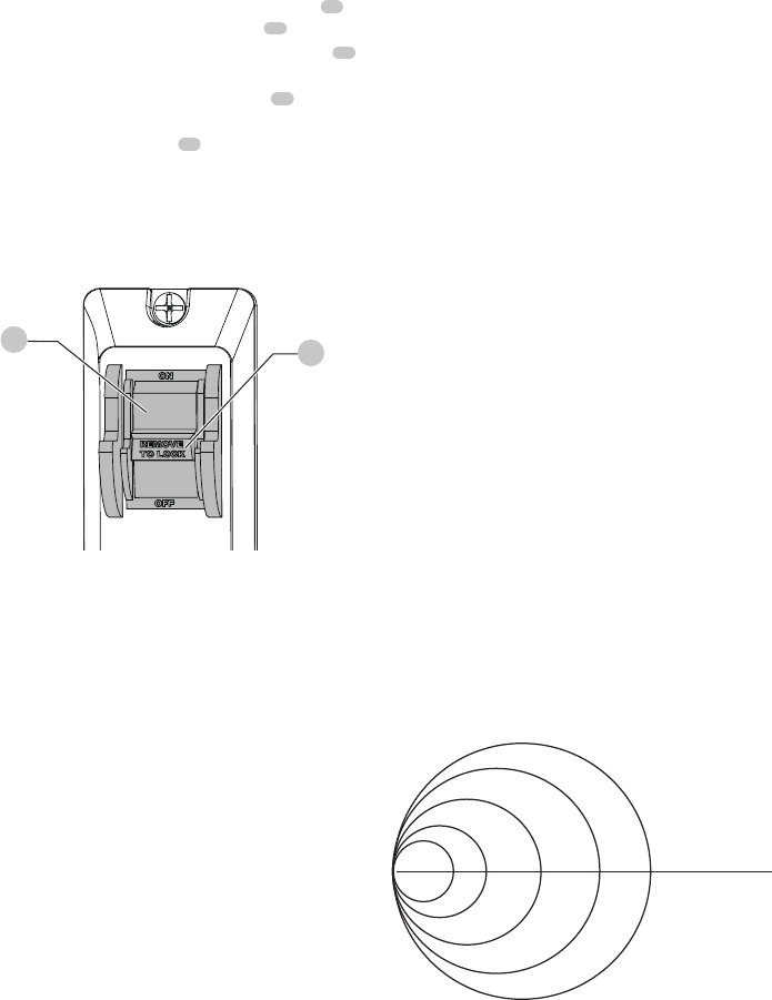
"ON/OFF" Switch (Fig. S)
The switch with safety key is intended to prevent
unauthorized us of the band saw.
1.
To turn the band saw ON, insert the black safety key
51
into the key slot in the center of the switch
14
.
2. Push the key firmly into the slot, then push the switch
14
to the ON position to start the band saw.
3. To turn the band saw OFF, push
the switch
14
to OFF
position.
4. Remove the
black
safety
key
51
by pulling it outward
when the saw is complete stop.
WARNING: Remove the
black
safety
key whenever the
saw is not in use. Place it in a safe place and out of reach
of children.
General Cutting
WARNING: For your safety, read and understand all
SAFETY INSTRUCTIONS on pages 4-7 before using the
band saw.
Operating band saws involves a certain amount of hazard.
Before attempting regular work, use scrap lumber to check
the settings, and to get the feel of operating the band
saw. Read instructions and plan your work before cutting a
workpiece.
Do not turn the power ON until after you have made all
adjustments, checked that the guard is in place, and turned
the wheel by hand to make sure all parts work properly.
Always keep the guide assembly 1/8 in. (3.2 mm) above the
workpiece.
Do not force the workpiece against the blade. Light contact
permits easier cutting and prevents unwanted friction and
heating of the blade.
Sharp saw blades need little pressure for cutting. Steadily
move the workpiece against the blade without forcing it.
Fig. S
51
14
To avoid twisting the blade do not turn sharp corners; saw
around corners.
A band saw is basically a “curve-cutting” saw. It is not
capable of doing intricate inside cutting as can be done
with a scroll saw.
It is also used for straight line operations such as
crosscutting, ripping, mitering, beveling, compound cutting,
and resawing.
WARNING: To avoid blade breakage, fire or other
damage or injury, NEVER use this band saw to cut
metals.
Cutting Curves
When cutting curves, carefully turn the workpiece so the blade
may follow without twisting. If the curve is so sharp that you
repeatedly back up and cut new kerf, use a narrower blade, or
a blade with more set (teeth further apart). When a blade has
more set, the workpiece turns easier but the cut is rougher.
When changing a cut, do not withdraw the workpiece from
the blade. The blade may get drawn off the wheels. To
change a cut, turn the workpiece and saw out through the
scrap material area.
When cutting long curves, make relief cuts as you go along.
Circle Cutting (FIG. T)
1. Adjust the guide assembly to 1/8 in. (3.2 mm) above
the workpiece.
2. Use both hands while feeding the work into the blade.
Hold the workpiece firmly against the table. Do not
force the work and operate with gentle pressure.
3. The smallest diameter circle that can be cut is
determined by the width of the blade. For example,
a 1/4 in. (6.4 mm) wide blade will cut a minimum
diameter of approximately 1-1/2 in. (38.1 mm).
Fig. T
1/2 in. D
1/8 in.
1-1/2 in. D
2-1/2 in. D
3/16 in.
1/4 in.
3/8 in.
1/2 in.
Minimum
Circle Diameter
Blade Width
(3.2 mm)
(4.8 mm)
(6.4 mm)
(9.5 mm)
(12.7 mm)
(12.7 mm)
(38.1 mm)
(50.8 mm)
(63.5 mm)
1 in. D
(25.4 mm)
2 in. D

15
ENGLISH
Blade Selection (Fig. U)
CAUTION:
Blade teeth are sharp. Use care when
handling a saw blade.
CAUTION:
For longest wear and best cutting results,
use the correct blade thickness, width, and temper for
the type of material you will cut.
When sawing small curves and delicate work, use narrow
blades. Otherwise, use the widest blade as possible. (Please
refer Fig. T)
For cutting wood and similar materials with this band saw,
purchase blades in width up to 1/2 in. (12.7 mm), and a
length of 59-1/2 in. (1,511.3 mm).
Do not cut metals with this band saw.
Fig. U
Operation
Recommended Blade Width In Inches (mm)
Cross Cutting
1/8, 1/4, 3/8 in. (3.2, 6.4 ,9.5 mm)
Mitering
1/8, 1/4, 3/8 in. (3.2, 6.4 ,9.5 mm)
Beveling
1/8, 1/4, 3/8 in. (3.2, 6.4 ,9.5 mm)
Compound
Cutting
1/8, 1/4, 3/8 in. (3.2, 6.4 ,9.5 mm)
Circle Cutting
See chart on Fig. T
Curve Cutting
1/8, 1/4 in. (3.2, 6.4 mm)
MAINTENANCE
General Maintenance
WARNING: For you own safety, turn the switch
OFF and remove the plug from power source
before maintaining, cleaning, adjusting or
lubricating your band saw.
WARNING: To avoid fire or toxic reaction, never
use gasoline, naphtha acetone, lacquer thinner
or similar highly volatile solvents to clean the
band saw.
WARNING: To avoid eye injury from blowing
debris, wear safety goggles when blowing out
sawdust.
WARNING: To avoid injury from unexpected
starting or electrical shock, unplug the power
cord before working on the saw.
WARNING: To avoid electrical shock, fire or
injury, use only parts identical to those identified
in the parts list. Reassemble exactly as the original
assembly to avoid electrical shock.
Maintenance
Use only mild soap and damp cloth to clean the tool. Never
let any liquid get inside the tool; never immerse any part of
the tool into a liquid.
Band Saw
Sawdust will accumulate under the table and base. This
could cause difficulty in the movement of the table when
setting up a band saw cut. Frequently blow out or vacuum
up the sawdust. Keep your band saw clean. Remove the
sawdust from the inside. Vacuum or blow out frequently.
Do not allow debris to build up on the table, the guides
or the support bearings. Clean them with gum and pitch
remover.
NOTE: Do not immerse the support bearings in the gum
and pitch remover.
Apply a thin coat of paste wax on the table so that the
wood slides easily while cutting.
Blade Wheel Tires
Pitch and sawdust that build up on the tires should be
removed with a stiff brush or scraped off with a piece of
wood.
NOTE: To avoid damaging the tires do not use a sharp knife
or any kind of solvent.
When the tires are worn, they should be replaced. When
replacing the tires, stretch them around the wheels but do
not glue them on.

ENGLISH
16
Motor
Frequently blow or vacuum out any sawdust from the
motor. Follow lubrication instruction on the motor label.
WARNING: To avoid electrocution or fire, immediately
replace a worn, cut or damaged power cord.
Adjusting The Upper Blade Guide Travel
(Fig. V)
If the upper blade guide assembly is not move up and down
easily or falls when the lock knob is loosened, the following
adjustment should be performed.
1. Loosen the upper guide lock knob
25
by turning it
counterclockwise.
2. Using a Phillips screwdriver, tighten or loosen the
two screws
52
located beside the upper guide lock
knob
25
to adjust the blade guide travel.
3. Move the blade guide assembly
41
up and down to
check for smooth movement and ability to hold in
position.
4. Make further adjustments to the two screws if required.
When blade guide is properly adjusted, it should move
smoothly and able to hold in position when released.
5. Tighten the upper blade lock knob
25
by turning
clockwise.
Lubrication
All of the bearings are packed with grease at the factory.
They require no further lubrication.
CAUTION: Never put lubricant on the blade while it
is spinning.
Fig. V
52
52
25
41
Free Warning Label Replacement
If your warning labels become illegible or are missing, call
1-888-331-4569 for a free replacement.

17
ENGLISH
TROUBLESHOOTING GUIDE
BE SURE TO FOLLOW SAFETY RULES AND INSTRUCTIONS
For assistance with your product, visit our website at www.craftsman.com for a list of service centers, or call CRAFTSMAN
at 1-888-331-4569.
PLEASE READ THE FOLLOWING: The manufacturer and/or distributor is providing the buyer with a parts list and assembly
diagram in this manual as a reference tool only. Neither the manufacturer nor distributor make any representation or
warranty of any kind to the buyer regarding the accuracy of the list or diagram or that buyer is qualified and able to make
any repairs or replace any parts of the product. The manufacturer and/or distributor expressly recommend: that all repairs
and/or part replacements only be undertaken by a certified and licensed technician, and not by the buyer. The buyer
assumes all risk and liability, including injuries to persons and damage to property, associated with and arising out of any
attempt of the buyer at repairs or replacement of parts to the product.
GENERAL
PROBLEM CAUSE CORRECTION
Blade does not run in the
center of upper wheel.
1. Not tracking properly.
2. Defective blade.
1. Adjust tracking. See ASSEMBLY AND ADJUSTMENTS section - "BLADE
TRACKING."
2. Replace blade.
Band saw slows down
when cutting.
1. Belt too loose.
2. Cutting too small a radius.
3. Dull blade.
4. Overloading motor.
1. Adjust belt tension. See ASSEMBLY AND ADJUSTMENTS section-
"BLADE TENSION"
2. Stop feeding, back up the material slightly, until band saw speeds up.
3. Replace blade.
4. Slow down, trying to cut too fast. See "MOTOR TROUBLESHOOTING
GUIDE."
Blades breaking 1. Too much tension on the blade.
2. Kink in the blade caused by cutting too small a radius
or turning the material too fast when cutting.
1. Adjust belt tension. See ASSEMBLY AND ADJUSTMENTS section -
"BLADE TENSION."
2. Use correct cutting technique. See "GENERAL CUTTING" in the
OPERATION section.
Blade dulls too quickly. 1. Blade guides set too close to the teeth.
2. Cutting incorrect material.
1. Adjust upper and lower blade guides.
2. See OPERATION section - "BLADE SECTION."
Band saw vibrates. 1. Too much tension on motor belt. 1. Adjust tracking. See ASSEMBLY AND ADJUSTMENTS section - "DRIVE
BELT TENSION."

ENGLISH
18
PROBLEM CAUSE CORRECTION
Noisy operation. 1. Incorrect belt tension.
2. Loose motor pulley.
3. Loose pulley cover.
1. Adjust tension. See ASSEMBLY AND ADJUSTMENTS section - "DRIVE BELT
TENSION."
2. Readjust and tighten motor pulley set screw.
3. Readjust and tighten pulley cover mounting screws.
Motor will not start. 1. Not plugged into power outlet.
2. Switch and key not in ON position.
3. Motor cord cut or abraded.
4. Plug on cord is faulty.
5. Fuse on circuit breaks open.
6. Faulty motor.
1. Plug it into the power outlet.
2. Insert key and turn the switch ON.
3. Re-set; may be too many machines on line.
4. Contact Service Center or Authorized Service Station.
5. Contact Service Center or Authorized Service Station.
6. Contact Service Center or Authorized Service Station.
Motor will not start and fuse
or circuit breaker opens.
1.
Too many electrical machines.
2. Incorrect fuse.
3. Wheels do not rotate.
4. Undersized extension cord.
5. Short circuit.
1. Turn off other machines and try again.
2.
Try time delay fuse, or go to circuit with higher rated fuse or circuit
breaker.
3. Unplug and turn wheels by hand, move obstruction.
4. Use correct size extension cord, see page 7.
5. Contact Service Center or Authorized Service Station.
Motor fails to develop full
power.
1. Low line voltage.
2. Faulty motor or capacitor.
1. Check power line for proper voltage.
2. Contact Service Center or Authorized Service Station.
Motor overheats. 1. Overload on motor.
2. Poor ventilation of motor.
3. Capacitor failure.
1. Reduce load to motor, feed work slower into blade.
2. Unplug and clean out around motor. Provide better air circulation.
3. Contact Service Center or Authorized Service Station.
Motor stalls or slows. 1. Motor overload.
2. Low line voltage.
3. Loose wire connections.
4. Faulty motor.
1. Reduce load to motor, feed work slower into blade.
2. Check power line for proper voltage.
3. Contact Service Center or Authorized Service Station.
4. Contact Service Center or Authorized Service Station.
Frequent fuse or circuit
breaker failure.
1. Motor overload.
2. Overload of electrical circuit.
3. Incorrect fuse or circuit breaker.
1. Reduce load to motor, feed work slower into blade.
2. Too many electrical appliances on same circuit.
3.
Have electrician upgrade service to outlet.
MOTOR
19
ENGLISH
Register Online
Thank you for your purchase. Register your product now for:
• WARRANTY SERVICE: Registering your product will
help you obtain more efficient warranty service in case
there is a problem with your product.
• CONFIRMATION OF OWNERSHIP: In case of an
insurance loss, such as fire, flood or theft, your
registration of ownership will serve as your proof of
purchase.
• FOR YOUR SAFETY: Registering your product will
allow us to contact you in the unlikely event a safety
notification is required under the Federal Consumer
Safety Act.
Register online at www.craftsman.com/registration
Three Year Limited Warranty
CRAFTSMAN will repair or replace, without charge, any
defects due to faulty materials or workmanship for one year
from the date of purchase. This warranty does not cover
part failure due to normal wear or tool abuse. For further
detail of warranty coverage and warranty repair information,
visit www.craftsman.com or call 1-888-331-4569. This
warranty does not apply to accessories or damage caused
where repairs have been made or attempted by others.
THIS LIMITED WARRANTY IS GIVEN IN LIEU OF ALL OTHERS,
INCLUDING THE IMPLIED WARRANTY OF MERCHANTABILITY
AND FITNESS FOR A PARTICULAR PURPOSE, AND EXCLUDES
ALL INCIDENTAL OR CONSEQUENTIAL DAMAGES. Some
states do not allow limitations on how long an implied
warranty lasts or the exclusion or limitation of incidental
or consequential damages, so these limitations may not
apply to you. This warranty gives you specific legal rights
and you may have other rights which vary in certain states
or provinces.
90 DAY MONEY BACK GUARANTEE
If you are not completely satisfied with the performance of
your CRAFTSMAN Power Tool, Laser, or Nailer for any reason,
you can return it within 90 days from the date of purchase
with a receipt for a full refund – no questions asked.
LATIN AMERICA: This warranty does not apply to products
sold in Latin America. For products sold in Latin America,
see country specific warranty information contained either
in the packaging, call the local company or see website for
warranty information.

ENGLISH
20
I.D.No. Description Size Q’ty I.D.No. Description Size Q’ty
X7BF MOTOR ASS’Y 1 X7CW SHAFT 1
X7BH LOWER BEARING GUIDE ASS’Y 1 X7CX HEX NUT 5
X7BJ LOWER BLADE GUIDE SUPPORT 1 X7CY HEX BOLT M6*20 4
X7BL LOWER BLADE WHEEL ASS’Y 1 X7CZ DUST PORT 1
X7BM UPPER BLADE WHEEL ASS’Y 1 X7D1 ADJUSTING HANDLE BASE 1
X7BQ UPPER BEARING GUIDE ASS’Y 1 X7D2 ADJUSTING GEAR 1
X7BR UPPER BLADE GUIDE SUPPORT 1 X7D3 HEX SCREW M6*25 2
X7BS UPPER GUIDE SLIDE BAR ASS’Y 1 X7D4 FLAT WASHER 2
X7C0 HEX WRENCH 2 MM 1 X7D7 MOTOR 1
X7C1 HEX WRENCH 4 MM 1 X7D8 FLAT WASHER 2
X7C2 OPEN END WRENCH 1 X7D9 HEX SCREW M8*25 2
X7C3 HEX BOLT 1 X7DA POWER CORD 1
X7C4 LOWER BLADE GUIDE SUPPORT BASE 1 X7DB CLIP 2
X7C5 WAVY WASHER φ6 1 X7DD WING LOCKING NUT 1
X7C6 CAPACITOR BOX 1 X7DE HEX NUT 1
X7C7 PHILIPS SCREW & FLAT WASHER M4*6 2 X7DF FLAT WASHER 3
X7C8 CAPACITOR 1 X7DH TENSION SPRING 1
X7C9 SPRING WASHER 1 X7DJ BLOCK 1
X7CA LOWER BLADE GUIDE SUPPORT 1 X7DL BLADE LOWER GUARD 1
X7CB LOWER SUPPORT SHAFT 1 X7DM HEX SCREW M6*8 2
X7CC MITER GAUGE POINTER 1 X7DN HEX NUT 1
X7CD PAN HEAD SCREW WITH FLAT M5*8 1 X7DP GUIDE PLATE 1
& SPRING WASHER X7DQ DRIVEN PULLEY 1
X7CE MITER GAUGE 1 X7DR FLAT WASHER 1
X7CG SLIDE BAR 1 X7DS HEX SCREW M5*10 1
X7CH FLAT WASHER 2 X7DT LOWER WHEEL SHAFT 1
X7CJ WING NUT 1 X7DU SPRING WASHER 1
X7CK HEX SCREW 2 X7DV HEX NUT 1
X7CL HEX BOLT 4 X7DW BELT 1
X7CM ANGLE SUPPORT 1 X7DX PAN HEAD SCREW WITH M4*8 6
X7CN GUIDE BLOCK 2 FLAT & SPRING WASHER
X7CR TABLE INSERT 1 X7DY HEX SCREW M5*15 2
X7CS HEX BOLT 1 X7DZ HEX SCREW M5*10 5
X7CT SCALE POINTER 1 X7E0 BEARING FASTENING SCREW 2
X7CV LOCKING SPRING 2 X7E1 BALL BEARING 2
PARTS LIST
9" (228 mm) Band Saw
Parts list for band saw - A

21
ENGLISH
9" (228 mm) Band Saw
Parts list for band saw - B
I.D.No. Description Size Q’ty I.D.No. Description Size Q’ty
X7E2 FLAT WASHER 4 X7F2 BLADE TRACKING WINDOW 1
X7E3 UPPER SUPPORT SHAFT 1 X7F3 PHILIPS SCREW M4*10 6
X7E4 UPPER BLADE GUIDE SUPPORT 1 X7F4 NUT 4
X7E5 PIN 4 X7F5 SPRING WASHER 3
X7E6 HEX SCREW M4*4 1 X7F6 HEX SCREW M6*10 2
X7E7 UPPER GUIDE SLIDE BAR 1 X7HT SPRING WASHER 1
X7E8 SLIDE BOARD 1 X7HU PHILIPS SCREW M5*16 3
X7E9 PHILIPS SCREW 1 X7HV SPRING WASHER 3
X7EA PLATE SPRING 1 X7HW HEX SCREW M4*8 4
X7EB GUIDE PLATE 1 X89T INSTRUCTION MANUAL 1
X7EC PHILIPS SCREW M5*10 7 X89V ROTATING LABEL 1
X7ED GUIDE BASE 1 X89W MOTOR LABEL 1
X7EE LOCKING PAD 1 X89X TRADEMARK LABEL 1
X7EF SWITCH PLATE 1 X89Y WARNING LABEL 1
X7EG SWITCH 1 X89Z TENSION HANDLE 1
X7EH HEX NUT 2 X8A0 SAW BODY 1
X7EJ CARRIAGE BOLT M8*85 1 X8A1 UPPER DOOR 1
X7EK U TYPE SUPPORT 1 X8A2 LOWER DOOR 1
X7EL BLADE WHEEL 2 X8A3 MITER GAUGE SCALE LABEL 1
X7EM CONNECTION SHAFT 1 X8A9 MITER GAUGE KNOB 1
X7EN WASHER 2 X8AA TABLE LOCKING KNOB 1
X7EP UPPER WHEEL SHAFT BASE 1 X8AB WORK TABLE 1
X7EQ UPPER WHEEL SHAFT 1 X8AC GEAR HANDLE 1
X7ES BRUSH 1 X8AD ADJUSTING HANDLE 1
X7ET CARRIAGE BOLT M8*70 1 X8AE ECCENTRIC LOCKING KNOB 2
X7EU IDLER PULLEY 1 X8AF LOCKING KNOB 1
X7EV TIRE 2 X8AG BLADE WHEEL ADJUSTING KNOB 1
X7EX INTERNAL CIRCLIP φ26 4 X8AH WORK TABLE ASS’Y 1
X7EY BALL BEARING 4 X8AJ MITER GAUGE ASS’Y 1
X7EZ CIRCLIP FOR SHAFT 2 X8AK LOWER DOOR ASS’Y 1
X7F0 BLADE 1 X8AL UPPER DOOR ASS’Y 1
ENGLISH
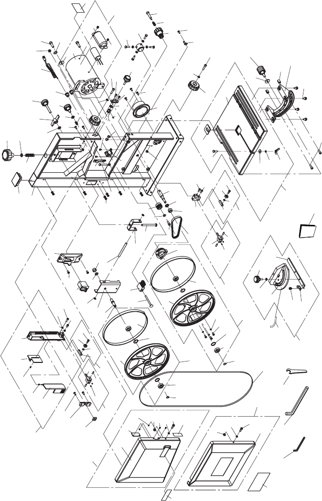
22
9" (228 mm) Band Saw
Schematic for band saw
X7EB
X7BS
X8AL
X89X
X8A1
X7F2
X7F4
X7BJ
X7EY
X7EX
X7HU
X7HV
X7EH
X7F3
X7F5
X7F4
X7F5
X7F6
X8A2
X89Y
X7EZ
X7EY
X7F6
X7BR
X7BQ
X7EC
X7ED
X7HW
X7E5
X7E4
X7E1
X7E0
X7E2
X7E3
X7DY
X7E2
X7EF
X7DJ
X8A0
X7DH
X89Z
X7DD
X8AF
X7DF
X8AG
X7DB
X7DA
X7DE
X7HT
X7D9
X7D8
X7D7
X7C6
X89W
X7C7
X7DF
X7F3
X7DN
X7EK
X7EJ
X7DY
X7DZ
X7BH
X8AH
X89T
X7CK
X7DX
X7EM
X7ES
X7ET
X7EV
X7EX
X7EL
X7EG
X7C9
X7EL
X7EV
X7EU
X7DS
X7DR
X7DQ
X7DW
X7CA
X8A9
X7CG
X7CH
X7CE
X7CD
X8A3
X7CC
X7E5
X7HW
X7DV
X7DU
X7DT
X7C4
X7CB
X7E2
X7E1
X7E0
X7CH
X7F5
X7CJ
X7EN
X7EP
X7EQ
X7DZ
2
2
2
2
2
2
2
2
2
2
6
3
3
2
2
X7EE
X7EA
X7E9
X7E8
X7E7
X8AK
X7C0
X7C1
X7C2
X7F0
X7EZ
X7BM
X7BL
X8AJ
2
2
X7EC
X7F4
X7DP
X7DL
X7F3
X7CX
X7C3
2
2
2
2
X7DM
X7D2
X7DF
X8AE
X7CV
X7D4
X7E6
X7D1
X7C5
X7EC
X7CZ
X7F4
X8AD
X7DZ
X7D3
X7C8
2
X7BF
X7CY
X7CX
X7CW
X7CV
X8AC
X7DZ
X7CT
X7D3
X7D4
X8AE
X8AB
X7CR
X7CS
X8AA
X7CN
X7CM
X7CL
X7D8
4
4
3
4
2
2
2
2
X89V
23
ENGLISH
NOTES
ENGLISH
24
NOTES
