#22
The 1.2 PureTech turbo engine is still causing lots of trouble for its owners. At issue is premature
degradation of the engine oil, which leads to timing belt wear – a problem already discussed in
connection with the naturally aspirated version.
But in the turbo version, when the timing belt disintegrates, the residue gradually contaminates the
engine oil and can potentially plug the vacuum pump, the variable valve timing solenoids, or the
(filter) screen of the oil pump.
There are several adverse impacts: if the vacuum pump plugs up, the power brake system fails,
which is no small problem, as you can imagine. Braking then requires tremendous force on the
brake pedal. These engines have also experienced lubrication issues (loss of oil pressure) or
camshaft and valve fouling.
As a result, a safety recall has been issued.
The recalled vehicles include all Peugeot (recall code JZR), Citroën and DS (recall code HFC)
models equipped with the 1.2 Puretech 110 hp or 130 hp engine and manufactured between
March 2013 and April 2017.
The source of the problem relates to the rapid degradation of engine oil, primarily in vehicles
operated relatively infrequently (less than 15,000 km per year) and where the vast majority of that
usage involves city driving. Under these usage conditions, the 1.2 PureTech is susceptible to oil
dilution, whereby fine droplets of unburnt fuel slide down the cylinder walls and mix with the oil in
the pan below. The resulting mixture turns out to be abrasive for the belt – and this explains the
wear. In the absence of a technical solution that prevents this condition, the only way to protect the
belt on these infrequently used cars is to change their engine oil annually. Which explains why the
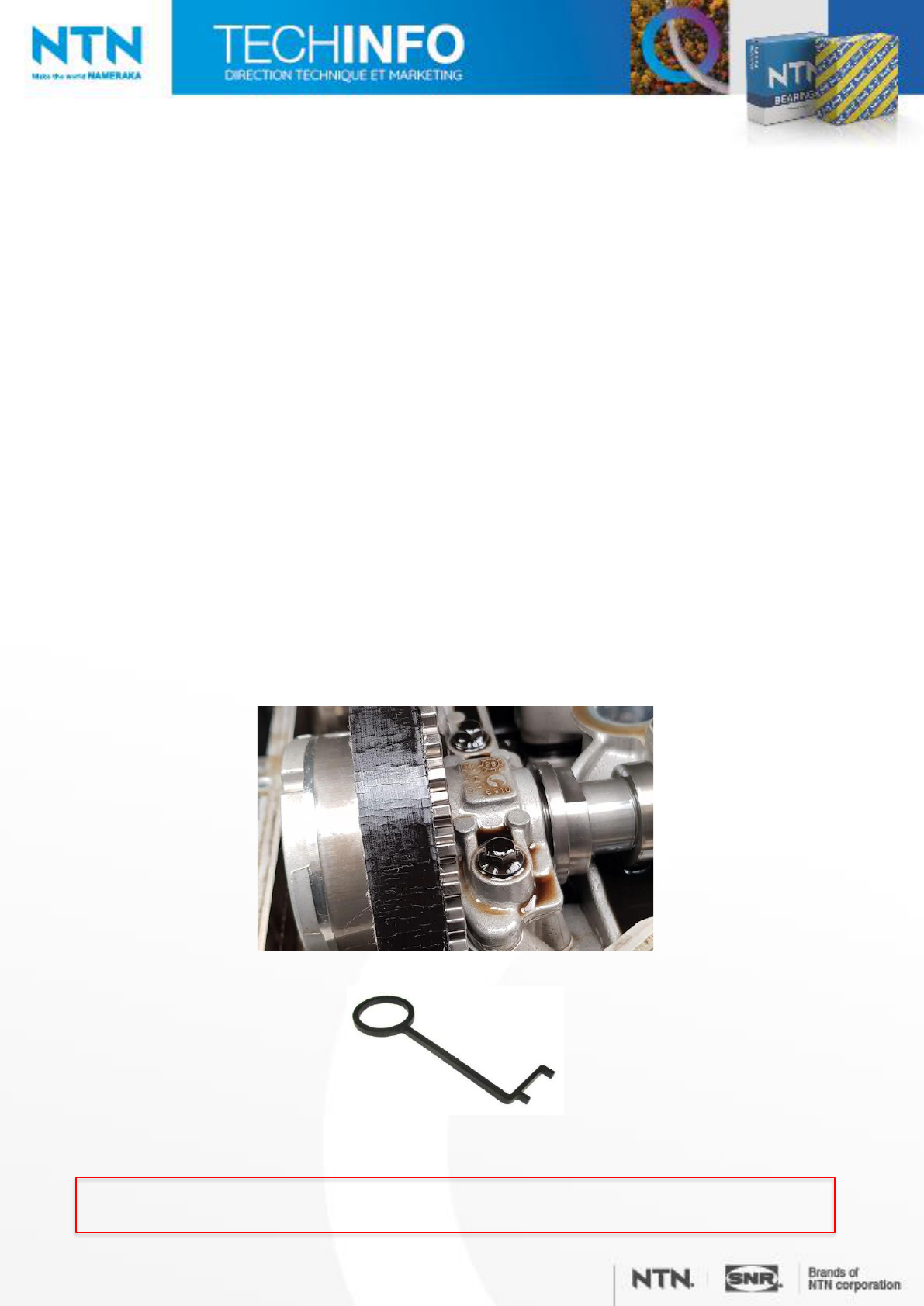
manufacturer recommends verifying the condition of the belt via the oil fill port during every routine
maintenance. Basically, when topping up the oil, you pour it into a hole situated over the timing belt.
Through that same hole, you can see part of the belt and this lets you determine its condition.
The belt should be inspected (belt width check) using a timing belt checking gauge at three
different points (crankshaft rotation).
Timing belt checking gauge
OE (G-0109-6)
NOTE: The replacement interval for the timing belt is now 100,000 km or 6 years.
KD459.70 /06-2022

Belt width must be checked.
If the belt width does not meet the specification, the lower oil pan must be removed to inspect the
oil pump screen.
➢ The belt need not be replaced unless it does not meet the specification. If it does require
replacement, the vacuum pump must also be replaced.
➢ If the oil pump screen is slightly plugged, it must be cleaned; the oil pump solenoid valve must
be replaced; the variable valve timing solenoid valves can either be cleaned or replaced; the
hollow screw of the oil supply line to the turbo must be replaced; and of course the vacuum
pump and the complete engine valve timing system must be replaced.
➢ If the screen is completely plugged, the oil pump must also be replaced.

And in all cases, the engine control unit must be reprogrammed to – as the recall notice
states – "update the engine control unit for the purposes of improving the power brake
system diagnostics and to eliminate any risk of reduction or loss of braking function."
In other words, the car will illuminate the oil pressure loss indicator on the instrument panel
earlier to show that there's a problem.

Vehicles
Peugeot
208 I EB2 DT (HNZ) 1.2 L THP 110 hp
208 II
EB2 ADTD 1.2 L THP 100 hp
EB2 DTS (HNY) 1.2 L THP 130 hp
2008
EB2 DT (HNZ) 1.2 L THP 110 hp
EB2 DTS (HNY) 1.2 L THP 130 hp
2008 II
EB2 ADTD 1.2 L THP 100 hp
EB2 DTS (HNY) 1.2 L THP 130 hp
EB2 ADTX 1.2 L THP 155 hp
308 II
EB2 DT (HNZ) 1.2 L THP 110 hp
EB2 DTS (HNY) 1.2 L THP 130 hp
Partner EB2 DT (HNZ) 1.2 L THP 110 hp
Rifter
EB2 DT (HNZ) 1.2 L THP 110 hp
EB2 DTS (HNY) 1.2 L THP 130 hp
3008 I EB2 DTS (HNY) 1.2 L THP 130 hp
3008 II EB2 DTS (HNY) 1.2 L THP 130 hp
5008 EB2 DTS (HNY) 1.2 L THP 130 hp
5008 II EB2 DTS (HNY) 1.2 L THP 130 hp
Citroën
C4 SpaceTourer EB2 DTS (HNY) 1.2 L THP 130 hp
C3 II EB2 DT (HNZ) 1.2 L THP 110 hp
C3 III EB2 DT (HNZ) 1.2 L THP 110 hp
C4 II
EB2 DT (HNZ) 1.2 L THP 110 hp
EB2 DTS (HNY) 1.2 L THP 130 hp
C4 Cactus
EB2 DT (HNZ) 1.2 L THP 110 hp
EB2 DTS (HNY) 1.2 L THP 130 hp
C4 Picasso II
EB2 DT (HNZ) 1.2 L THP 110 hp
EB2 DTS (HNY) 1.2 L THP 130 hp
C3 Picasso EB2 DT (HNZ) 1.2 L THP 110 hp
C3 Aircross
EB2 DT (HNZ) 1.2 L THP 110 hp
EB2 DTS (HNY) 1.2 L THP 130 hp
Berlingo II EB2 DT (HNZ) 1.2 L THP 110 hp
Berlingo III
EB2 DT (HNZ) 1.2 L THP 110 hp
EB2 DTS (HNY) 1.2 L THP 130 hp
DS4 EB2 DTS (HNY) 1.2 L THP 130 hp
DS3
EB2 DT (HNZ) 1.2 L THP 110 hp
EB2 DTS (HNY) 1.2 L THP 130 hp
DS3 Crossback
EB2 ADTD 1.2 L THP 100 hp
EB2 DTS (HNY) 1.2 L THP 130 hp
EB2 ADTX 1.2 L THP 155 hp
Toyota
ProAce City
EB2 DT (HNZ) 1.2 L THP 110 hp
EB2 DTS (HNY) 1.2 L THP 130 hp
EB2 DTS (HNY) 1.2 L THP 130 hp
Opel
Crossland X
EB2 DT (HNZ) 1.2 L THP 110 hp
EB2 DTS (HNY) 1.2 L THP 130 hp
Corsa VI
EB2 ADTD 1.2 L THP 100 hp
EB2 DTS (HNY) 1.2 L THP 130 hp
Mokka II
EB2 ADTD 1.2 L THP 100 hp
EB2 DTS (HNY) 1.2 L THP 130 hp
EB2 ADTX 1.2 L THP 155 hp
Grandland X
EB2 DT (HNZ) 1.2 L THP 110 hp
EB2 DTS (HNY) 1.2 L THP 130 hp
Recommendations
Turn the engine only by rotating the crankshaft pulley in the direction of operation.
Do not rotate the crankshaft or the camshafts while the timing belt has been removed.
Make timing belt adjustments only while the engine is cold.
It is recommended not to reuse accessory belts after removal: always replace them instead.
Systematic replacement of parts
KD459.70
Name Quantity
Seal, crankshaft 1
Seal, oil separator 1
Seal, vacuum pump 1
Seal, crankcase, timing belt cover 1
Belt, water pump 1
Bolt, crankshaft pulley 1
Bolts, dephaser pulleys 2

Required tools
Outils spéciaux nécessaires
SNR préconise les outillages Clas OM 3747, OM 4141 et OM 4058
Tuyau de purge
OE (4192-T)
Bouchon de fermeture
OE (0189-Q)
Outil de blocage de l'arbre à
cames d'admission
OE (0109-2C)
Outil de blocage
de l'arbre à cames
d'échappement
OE (0109-2D)
Outil de blocage du
volant moteur
OE (0197-N)
Goupille de blocage
du galet tendeur
OE (0188-Q1)
Outil de montage
courroie d’accessoires
OE (0109-1B)
Gabarit de courroie de
distribution
OE (G-0109-6)
Name Figures
Recommendations
Tightening
torque
Vacuum pump bolts (3)
(see Figure 6)
Use a new seal.
8 Nm
Timing belt cover bolt (1)
(see Figure 12)
(see Figure 21)
Crankshaft pulley bolt (3)
(see Figure 25)
Use new bolt.
Step 01
20 Nm
Step 02
25 Nm
Step 03
45°
Tensioner roller bolt
GT359.41
(1)
(see Figure 24)
20 Nm
Idler roller bolt
GE359.32 (3)
(see Figure 23)
20 Nm
Crankshaft gear bolt (6)
(see Figure 23)
Use a new bolt.
Step 01
50 Nm
Step 02
180°
Camshaft dephaser bolts (2)
(see Figure 19)
Use new bolts
Step 01
20 Nm
Step 02
120°
Oil separator bolts
(1) - (16)
(see Figure 28)
Tighten in recommended
order.
Use a new seal.
10 Nm
Tightening torques

Abb
r.
Name
A
Alternator
AC
Air conditioner compressor
CRS
Crankshaft
T
Tensioner roller
WP
Water pump
Removal
Place the vehicle on a lifting platform.
Remove the engine cover.
Raise the vehicle.
Remove the right front wheel.
Remove the right front wheel arch liner.
Disconnect the battery.
Compress the tensioning device by rotating it anticlockwise with a suitable tool. (1)
Insert the blocking tool to fix the tensioner roller in place. (2)
Special tools required
Tensioner roller blocking tool (2) OE (0188-Q1)
Accessory belt routing
1 Accessory belt tensioning system
2 Tensioner roller blocking tool
Figure 1

Remove the accessory belt from the alternator and air conditioner compressor. (1)
Cut the accessory belt from the water pump and remove it. (1)
Figure 2
1 Accessory belt – alternator / air conditioner compressor
Figure 3
1 Accessory belt
– water pump
Attach purge line to the purge screw. (1)
Lower the fuel pressure.
Remove the vent hose.
Special tools required
Purge hose OE (4192-T)
NOTE: Collect any leaking fuel.
1 PCV valve
Figure 4
1 High
-pressure pump cover
2 Cable channel bolt
3 Engine wire harness
Remove the ignition coils.
Unscrew the air filter housing.
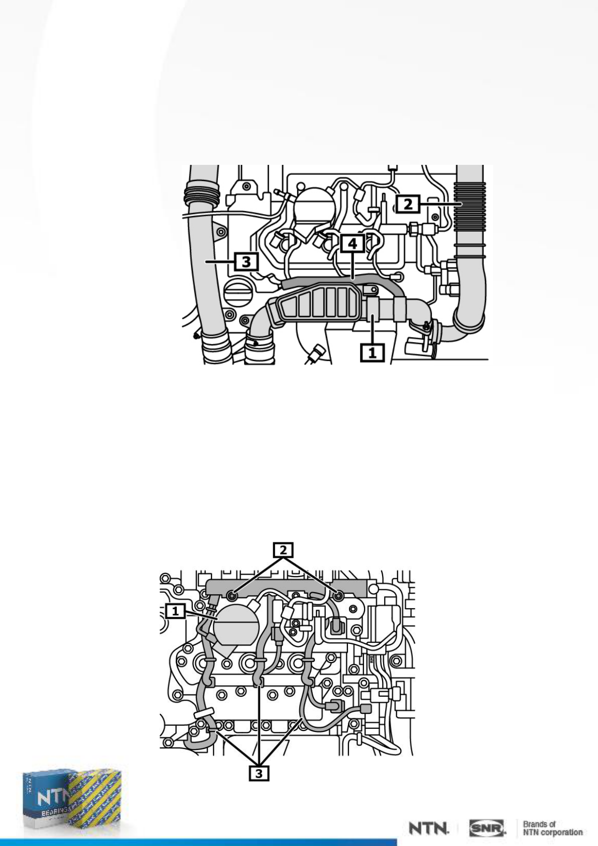
Remove the charge-air hose between the cooler and the turbocharger. (1)
Remove the air intake hose between the turbocharger and the air filter housing. (2)
Remove the charge-air ducts. (3)
Remove the hose from the vent housing on the engine block. (4))
Remove the high-pressure pump cover. (1)
Loosen the fuel line from the high-pressure pump.
Close the openings.
Unscrew the screws of the cable channel. (2)
Disconnect the engine wire harness connector.
Detach the engine lines from the body and set them aside. (3)
Special tools required
Caps OE (0189-Q)
1 Charge
-air duct
2 Inlet air duct
3 Charge
-air duct
4 Crankcase vent hose
Figure 5
Figure 6

Using the crankshaft pulley bolt, turn the crankshaft until the camshaft pulley reaches the
ignition timing position. Unscrew the oil separator bolts. (arrows)
Remove the oil separator. (1)
1 Oil separator
Remove the air intake duct. (1)
1 Air intake duct
Disconnect the vacuum lines from the vacuum pump. (1)
Disconnect the electrical connector(s). (2)
Unscrew the vacuum pump bolts. (3) (arrow)
Remove the vacuum pump. (4)
1 Vacuum line 2 Electrical connector
3 Vacuum pump bolts 4 Vacuum pump
Figure 7
Figure 8
Figure 9

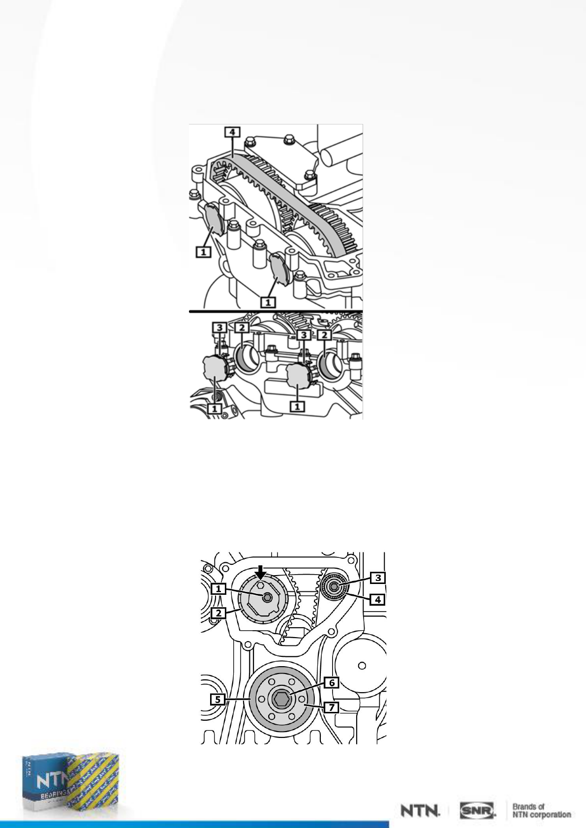
Turn the crankshaft in the direction of operation till the flat side of the positioning cam faces
upward. (1) (arrow)
1 Positioning cam
The notch of the exhaust camshaft should be in the vertical position. (1)
1 Exhaust camshaft actuator (cam)
Install the intake camshaft locking tool. (1)
Tighten the bolts securely. (2)
Special tools required
Intake camshaft locking tool (1) OE (0109-2C)
1 Intake camshaft locking tool 2 Bolts
Figure 10
Figure 11
Figure 12

Install the exhaust camshaft locking tool. (1)
Tighten the bolts securely. (2)
Special tools required
Exhaust camshaft locking tool (1) OE (0109-2D)
1 Exhaust camshaft locking tool 2 Bolts
Turn the crankshaft in the direction of rotation till the locating pin can be inserted into the
borehole of the flywheel through the engine block. (1)(2)
Check to see that the engine is correctly locked by turning the crankshaft gently in the opposite
direction.
Special tools required
Flywheel locking tool (1) OE (0197-N)
1 Flywheel locking tool 2 Flywheel
Figure 13
Figure 14

Unscrew the crankshaft pulley bolts. (3)
Remove the crankshaft pulley. (4)
Unscrew the timing belt cover screws. (1)
Remove the timing belt cover. (2)
1 Timing belt cover bolt 2 Belt cover
3 Crankshaft pulley bolts 4 Crankshaft pulley
Unscrew the tensioner roller bolt. (1)
Remove the tensioner roller. (2)
Remove the idler roller bolt. (3)
Remove the idler roller. (4)
Remove the seal. (5)
Unscrew the crankshaft gear bolt. (6)
Remove the drive pulley hub. (7)
1 Tensioner roller bolt 2 Tensioner roller
3 Idler roller bolt 4 Idler roller
5 Sealing washer 6 Crankshaft gear bolt
7 Drive pulley hub
Figure 15
Figure 16

Remove the caps. (1)
Remove the timing belt from the camshaft gears. (2)
1 Cap 2 Timing belt
Remove the crankshaft gear. (1)
Unscrew the camshaft gear bolts. (2)
Remove the camshaft dephasers. (3)
Extract the timing belt from above. (4)
1 Crankshaft gear 2 Timing belt
Figure 17
Figure 18
Installation
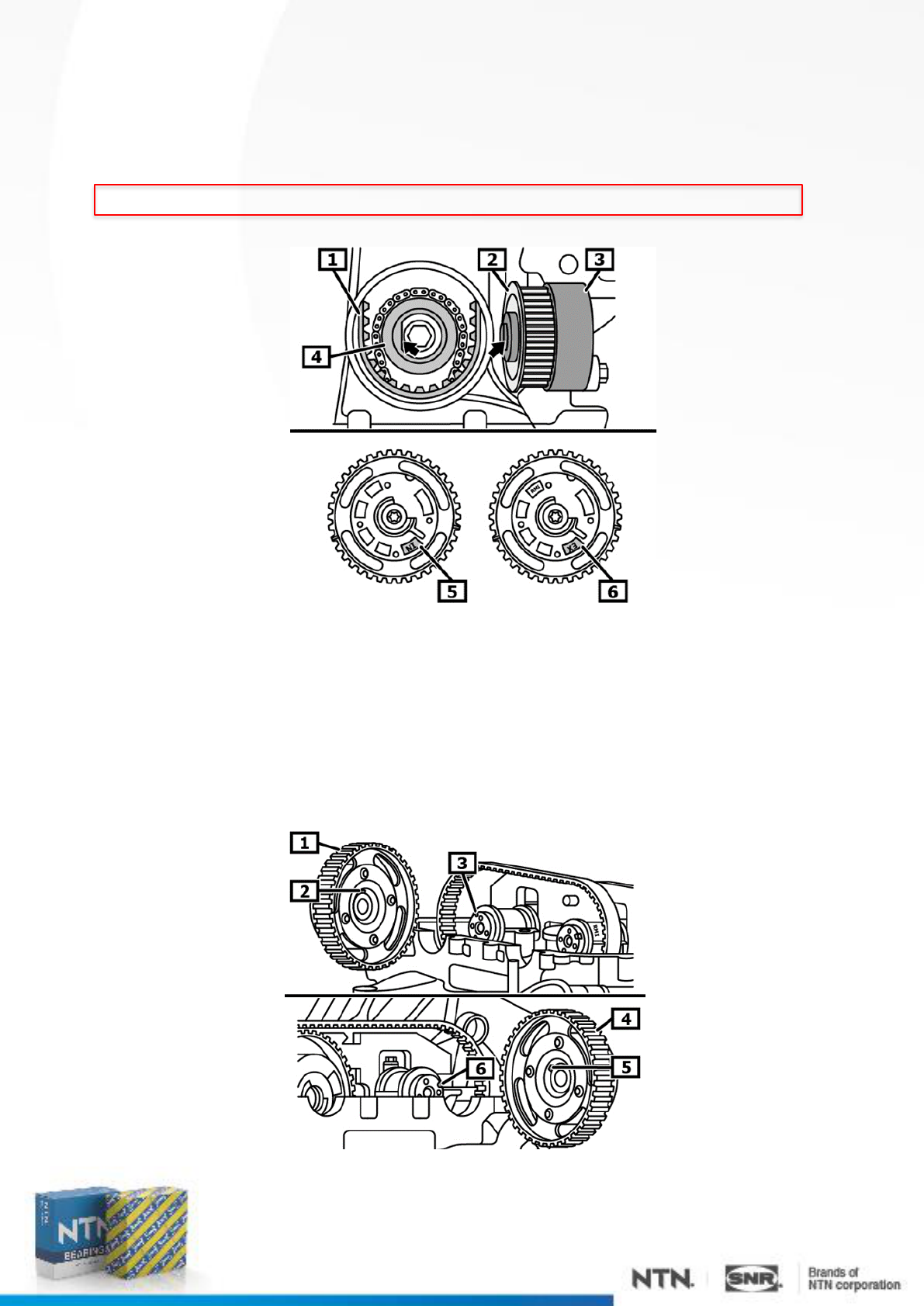
Install the timing belt CD41228. (1)
Install the pulley hub with the crankshaft gear. (2)(3)
Take note of the flat on the crankshaft and the recess of the hub! (3)(4) (arrows)
Check the camshaft gear markings. (5)(6)
1 Timing belt 2 Crankshaft gear
3 Drive pulley hub 4 Crankshaft
5 Intake camshaft gear marking 6 Exhaust camshaft gear marking
Install the exhaust camshaft gear. (1)
Take care to position it correctly. (2)(3)
Tighten the exhaust camshaft gear bolt. (2)
Install the intake camshaft gear.
Take care to position it correctly. (5)(6)
Tighten the intake camshaft gear bolt. (2)
1 Exhaust camshaft gear 2 Key
3 Camshaft keyway 4 Intake camshaft gear
5 Key
6 Camshaft keyway
Figure 19
Figure 20
Position belt CD41228 on the camshaft gears. (4)
Do not remove any excess jointing compound. (2)
Do not grease the seals. (3)
Install the caps. (1)
1 Cap 2 Jointing compound
3 Sealing rings 4 Timing belt CD41228
Tighten the bolt (6) of the crankshaft gear (7) to the specified torque.
Install the idler roller GE359.32 (4)
Remove the idler roller bolt. (3)
Install the idler roller GT359.41 (2)
Screw in the tensioner roller bolt. (1)
Figure 21
Figure 22
1 Tensioner roller bolt
2 Tensioner roller
GT359.41
3 Idler roller bolt
4 Idler roller
GE359.32
5 Seal
6 Crankshaft gear bolt
7 Crankshaft gear hub
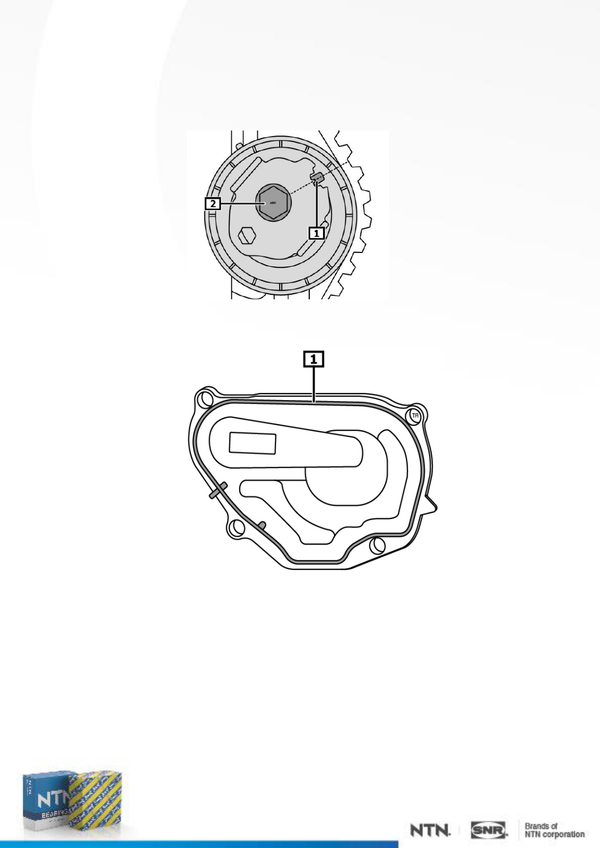
Tension the timing belt.
Turn the eccentric anticlockwise with an Allen wrench till the mark lines up with the reference
mark. (1)
Tighten the tensioner roller bolt to the specified torque. (2)
Replace the rubber seal of the timing belt cover. (1)
1 Seal
Figure 23
1 Reference mark
2 Tensioner roller bolt
Figure 24
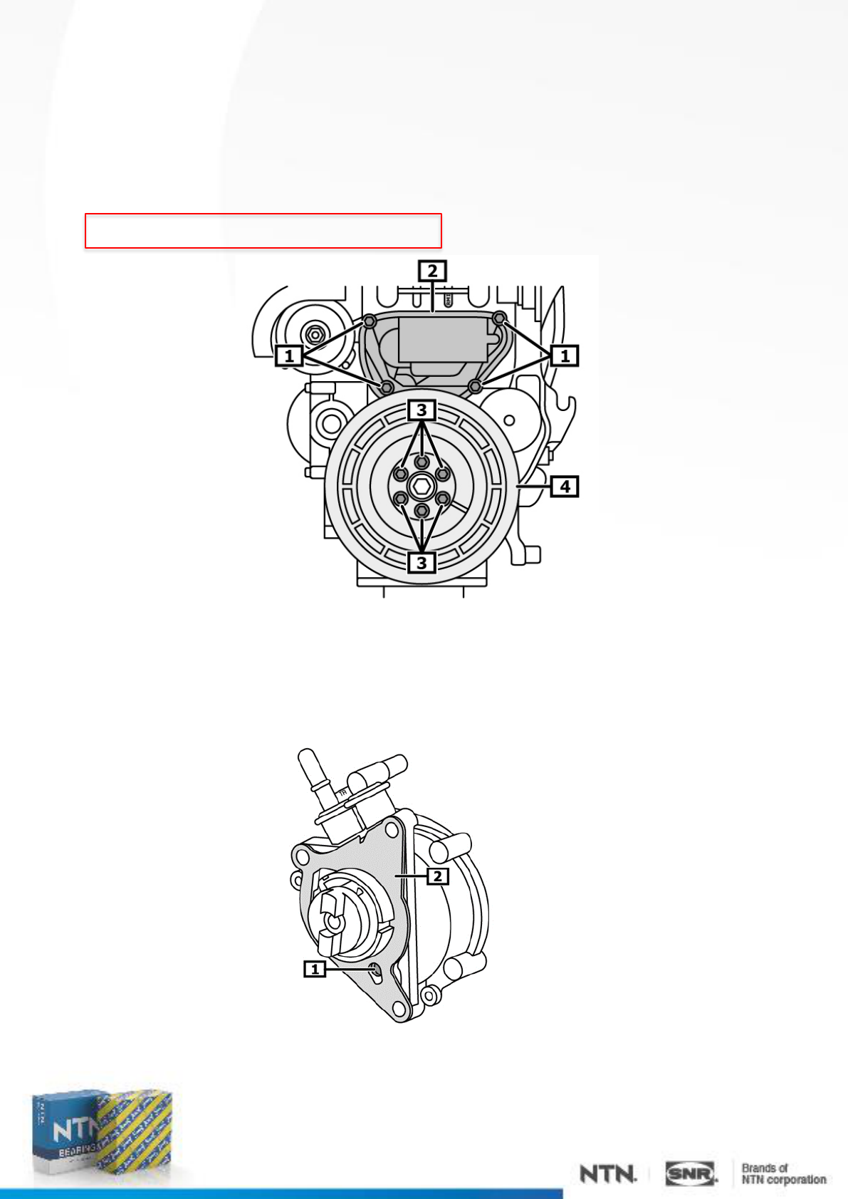
Install the timing belt cover (2) with a new seal.
Tighten the lower timing belt cover screws. (1)
Install the crankshaft pulley. (4)
Use new bolts. (3)
Tighten the crankshaft pulley bolts. (3)
NOTE: Follow all tightening torque specifications.
Check to see that the filter is installed on the vacuum pump. (1)
Clean the sealing surfaces.
Replace the gasket. (2)
Figure 25
1 Timing belt cover bolts
2 Timing belt cover
3 Crankshaft pulley bolts
4 Crankshaft pulley
Figure 26
1 Filter 2 Gasket

Replace the seal on the oil separator. (1)
1 Seal
Tighten the oil separator bolts in the order shown, from 1 to 16. (1) - (16)
Install the ignition coils.
1 - 16 Oil separator bolts
Figure 27
Figure 28

Re-install the accessory belt for the water pump (coolant pump).
Install the accessory belt installation tool. (1)
Position the accessory belt on the hook of the installation tool. (1) - (3)
Turn the crankshaft about 1 to 2 turns in the direction of operation.
Force the accessory belt onto the water pump pulley. (2)(4)
Turn the engine in the direction of operation until the accessory belt is fully seated in the
grooves of the pulley. (2)
Pay attention to the correct positioning of the accessory belt. (2)
If the water pump belt is not correctly positioned, the installation procedure must be repeated
with a new belt. (2) Special tools required
Installation tool (1) OE (0109-1B)
Install the accessory belt of the air-conditioner and alternator. (1)
Pay attention to the correct positioning of the accessory belt.
Figure 29
1 Installation tool 2 Accessory belt, water pump
3 Hook 4 Water pump belt pulley
Figure 30

Rotate the tensioning device anticlockwise with a suitable tool. (1)
Remove the tensioner roller blocking tool. (2)
Loosen the accessory belt tensioning device. (1)
Turn the engine through two rotations of the crankshaft in the direction of operation.
Pay attention to the correct positioning of the accessory belt.
Re-check the tension of the accessory belt. (1)(3)
The mark must correspond to the reference mark. (1)(3)
.
Connect the battery.
Start the engine.
Check to see that the belt tracks smoothly/correctly.
Take a test drive.
Document the timing belt replacement
NOTE: Using a diagnostic tool, read out the fault history.
Figure 31
Figure 32
1 Reference mark
2 Mounting hole
3 Wear mark
1 Accessory belt tensioner
2 Tensioner roller blocking tool
