
SUSE Linux Enterprise Server 15 SP5
Storage Administration
Guide

Storage Administration Guide
SUSE Linux Enterprise Server 15 SP5
This guide provides information about how to manage storage devices on a SUSE
Linux Enterprise Server.
Publication Date: August09,2024
https://documentation.suse.com
Copyright © 2006–2024 SUSE LLC and contributors. All rights reserved.
Permission is granted to copy, distribute and/or modify this document under the terms of the GNU Free Docu-
mentation License, Version 1.2 or (at your option) version 1.3; with the Invariant Section being this copyright
notice and license. A copy of the license version 1.2 is included in the section entitled “GNU Free Documentation
License”.

For SUSE trademarks, see https://www.suse.com/company/legal/ . All third-party trademarks are the property
of their respective owners. Trademark symbols (®, ™ etc.) denote trademarks of SUSE and its affiliates. Asterisks
(*) denote third-party trademarks.
All information found in this book has been compiled with utmost attention to detail. However, this does not
guarantee complete accuracy. Neither SUSE LLC, its affiliates, the authors nor the translators shall be held liable
for possible errors or the consequences thereof.
Contents
Preface xv
1 Available documentation xv
2 Improving the documentation xvi
3 Documentation conventions xvii
4 Support xix
Support statement for SUSE Linux Enterprise Server xix • Technology
previews xx
I FILE SYSTEMS AND MOUNTING 1
1 Overview of file systems in Linux 2
1.1 Terminology 3
1.2 Btrfs 3
Key features 4 • The root file system setup on SUSE Linux
Enterprise Server 4 • Migration from ReiserFS and ext file systems
to Btrfs 8 • Btrfs administration 10 • Btrfs quota support
for subvolumes 10 • Swapping on Btrfs 13 • Btrfs send/
receive 14 • Data deduplication support 17 • Deleting subvolumes
from the root file system 18
1.3 XFS 19
XFS formats 20
1.4 Ext2 21
1.5 Ext3 22
Easy and highly reliable upgrades from ext2 22 • Converting an ext2 file
system into ext3 22
iv Storage Administration Guide
1.6 Ext4 23
Reliability and performance 24 • Ext4 file system inode size and number of
inodes 24 • Upgrading to Ext4 27
1.7 ReiserFS 28
1.8 OpenZFS and ZFS 29
1.9 tmpfs 29
1.10 Other supported file systems 29
1.11 Blocked file systems 31
1.12 Large file support in Linux 32
1.13 Linux kernel storage limitations 33
1.14 Freeing unused file system blocks 34
Periodic TRIM 35 • Online TRIM 35
1.15 Troubleshooting file systems 36
Btrfs error: no space is left on device 36 • Btrfs: balancing data across
devices 38 • No defragmentation on SSDs 39
1.16 More information 39
2 Resizing file systems 41
2.1 Use cases 41
2.2 Guidelines for resizing 41
File systems that support resizing 42 • Increasing the size of a file
system 42 • Decreasing the size of a file system 43
2.3 Changing the size of a Btrfs file system 43
2.4 Changing the size of an XFS file system 44
2.5 Changing the size of an ext2, ext3, or ext4 file system 45
3 Mounting storage devices 46
3.1 Understanding UUIDs 46
v Storage Administration Guide
3.2 Persistent device names with udev 46
3.3 Mounting network storage devices 47
4 Multi-tier caching for block device operations 48
4.1 General terminology 48
4.2 Caching modes 49
4.3 bcache 50
Main features 50 • Setting up a bcache device 50 • bcache
configuration using sysfs 52
4.4 lvmcache 52
Configuring lvmcache 53 • Removing a cache pool 54
II LOGICAL VOLUMES (LVM) 56
5 LVM configuration 57
5.1 Understanding the logical volume manager 57
5.2 Creating volume groups 59
5.3 Creating logical volumes 62
Thinly provisioned logical volumes 65 • Creating mirrored volumes 66
5.4 Automatically activating non-root LVM volume groups 67
5.5 Resizing an existing volume group 68
5.6 Resizing a logical volume 69
5.7 Deleting a volume group or a logical volume 71
5.8 Disabling LVM on boot 71
5.9 Using LVM commands 72
Resizing a logical volume with commands 75 • Using LVM cache
volumes 77
vi Storage Administration Guide
5.10 Tagging LVM2 storage objects 78
Using LVM2 tags 79 • Requirements for creating LVM2
tags 79 • Command line tag syntax 80 • Configuration
file syntax 80 • Using tags for a simple activation control in a
cluster 82 • Using tags to activate on preferred hosts in a cluster 82
6 LVM volume snapshots 86
6.1 Understanding volume snapshots 86
6.2 Creating Linux snapshots with LVM 88
6.3 Monitoring a snapshot 88
6.4 Deleting Linux snapshots 89
6.5 Using snapshots for virtual machines on a virtual host 89
6.6 Merging a snapshot with the source logical volume to revert changes or
roll back to a previous state 91
III SOFTWARE RAID 94
7 Software RAID configuration 95
7.1 Understanding RAID levels 95
RAID0 95 • RAID1 96 • RAID2 and
RAID3 96 • RAID4 96 • RAID5 96 • RAID6 97 • Nested and
complex RAID levels 97
7.2 Soft RAID configuration with YaST 97
RAID names 100
7.3 Configuring stripe size on RAID 5 on AArch64 101
7.4 Monitoring software RAIDs 101
7.5 More information 102
8 Configuring software RAID for the root partition 103
8.1 Prerequisites for using a software RAID device for the root
partition 103
vii Storage Administration Guide
8.2 Setting up the system with a software RAID device for the root (/)
partition 104
9 Creating software RAID10 devices 111
9.1 Creating nested RAID 10 devices with mdadm 111
Creating nested RAID 10 (1+0) with mdadm 112 • Creating nested RAID 10
(0+1) with mdadm 114
9.2 Creating a complex RAID 10 116
Number of devices and replicas in the complex
RAID10 117 • Layout 118 • Creating a complex RAID10 with the YaST
partitioner 120 • Creating a complex RAID 10 with mdadm 123
10 Creating a degraded RAID array 126
11 Resizing software RAID arrays with mdadm 128
11.1 Increasing the size of a software RAID 129
Increasing the size of component partitions 130 • Increasing the size of the
RAID array 131 • Increasing the size of the file system 132
11.2 Decreasing the size of a software RAID 133
Decreasing the size of the file system 133 • Decreasing the size of the RAID
array 133 • Decreasing the size of component partitions 134
12 Storage enclosure LED utilities for MD software
RAIDs 137
12.1 The storage enclosure LED monitor service 138
12.2 The storage enclosure LED control application 139
Pattern names 140 • List of devices 143 • Examples 144
12.3 More information 144
13 Troubleshooting software RAIDs 145
13.1 Recovery after failing disk is back again 145
viii Storage Administration Guide
IV NETWORK STORAGE 147
14 iSNS for Linux 148
14.1 How iSNS works 148
14.2 Installing iSNS server for Linux 150
14.3 Configuring iSNS discovery domains 151
Creating iSNS discovery domains 152 • Adding iSCSI nodes to a discovery
domain 153
14.4 Starting the iSNS service 155
14.5 More information 155
15 Mass storage over IP networks: iSCSI 156
15.1 Installing the iSCSI LIO target server and iSCSI initiator 157
15.2 Setting up an iSCSI LIO target server 158
iSCSI LIO target service start-up and firewall settings 158 • Configuring
authentication for discovery of iSCSI LIO targets and initiators 159 • Preparing
the storage space 161 • Setting up an iSCSI LIO target
group 162 • Modifying an iSCSI LIO target group 166 • Deleting an iSCSI
LIO target group 166
15.3 Configuring iSCSI initiator 167
Using YaST for the iSCSI initiator configuration 167 • Setting up the iSCSI
initiator manually 170 • The iSCSI initiator databases 171
15.4 Setting up software targets using targetcli-fb 173
15.5 Using iSCSI disks when installing 177
15.6 Troubleshooting iSCSI 178
Portal error when setting up target LUNs on an iSCSI LIO target
server 178 • iSCSI LIO targets are not visible from other
computers 179 • Data packets dropped for iSCSI traffic 179 • Using iSCSI
volumes with LVM 179 • iSCSI targets are mounted when the configuration
file is set to manual 180
15.7 iSCSI LIO target terminology 180
ix Storage Administration Guide
15.8 More information 182
16 Fibre Channel storage over Ethernet networks:
FCoE 183
16.1 Configuring FCoE interfaces during the installation 184
16.2 Installing FCoE and the YaST FCoE client 185
16.3 Managing FCoE services with YaST 186
16.4 Configuring FCoE with commands 189
16.5 Managing FCoE instances with the FCoE administration tool 189
16.6 More information 192
17 NVMe-oF 193
17.1 Overview 193
17.2 Setting up an NVMe-oF host 193
Installing command line client 193 • Discovering NVMe-oF
targets 194 • Connecting to NVMe-oF targets 194 • Multipathing 195
17.3 Setting up an NVMe-oF target 196
Installing command line client 196 • Configuration steps 196 • Back up
and restore target configuration 199
17.4 Special hardware configuration 199
Overview 199 • Broadcom 199 • Marvell 200
17.5 Booting from NVMe-oF over TCP 201
System requirements 201 • Installation 201
17.6 More information 202
18 Managing multipath I/O for devices 203
18.1 Understanding multipath I/O 203
Multipath terminology 203
x Storage Administration Guide
18.2 Hardware support 205
Multipath implementations: device mapper and NVMe 205 • Storage array
autodetection for multipathing 205 • Storage arrays that require specific
hardware handlers 206
18.3 Planning for multipathing 206
Prerequisites 206 • Multipath installation types 207 • Disk management
tasks 208 • Software RAID and complex storage stacks 208 • High-
availability solutions 209
18.4 Installing SUSE Linux Enterprise Server on multipath systems 209
Installing without connected multipath devices 209 • Installing with
connected multipath devices 210
18.5 Updating SLE on multipath systems 211
18.6 Multipath management tools 211
Device mapper multipath module 212 • The multipathd
daemon 213 • The multipath command 216 • SCSI persistent
reservations and mpathpersist 217
18.7 Configuring the system for multipathing 218
Enabling, starting, and stopping multipath services 218 • Preparing
SAN devices for multipathing 220 • Partitions on multipath devices and
kpartx 221 • Keeping the initramfs synchronized 221
18.8 Multipath configuration 223
Creating /etc/multipath.conf 223 • multipath.conf
syntax 223 • multipath.conf sections 225 • Applying multipath.conf
modifications 226
18.9 Configuring policies for failover, queuing, and failback 227
Queuing policy on stand-alone servers 230 • Queuing policy on clustered
servers 230
18.10 Configuring path grouping and priorities 231
xi Storage Administration Guide
18.11 Selecting devices for multipathing 234
The blacklist section in multipath.conf 234 • The blacklist
exceptions section in multipath.conf 236 • Other options affecting device
selection 236
18.12 Multipath device names and WWIDs 238
WWIDs and device Identification 238 • Setting aliases for multipath
maps 239 • Using autogenerated user-friendly names 239 • Referring to
multipath maps 240
18.13 Miscellaneous options 242
Handling unreliable (“marginal”) path devices 243
18.14 Best practice 245
Best practices for configuration 245 • Interpreting multipath I/O
status 246 • Using LVM2 on multipath devices 247 • Resolving stalled I/
O 248 • MD RAID on multipath devices 248 • Scanning for new devices
without rebooting 248
18.15 Troubleshooting MPIO 249
Understanding device selection issues 249 • Understanding device
referencing issues 250 • Troubleshooting steps in emergency
mode 251 • Technical information documents 254
19 Sharing file systems with NFS 255
19.1 Overview 255
19.2 Installing NFS server 256
19.3 Configuring NFS server 257
Exporting file systems with YaST 257 • Exporting file systems
manually 259 • NFS with Kerberos 262
19.4 Configuring clients 262
Importing file systems with YaST 263 • Importing file systems
manually 264 • Parallel NFS (pNFS) 266
19.5 Operating an NFS server and clients behind a firewall 267
NFS 4.x 267 • NFS 3 268
xii Storage Administration Guide
19.6 Managing Access Control Lists over NFSv4 270
19.7 More information 271
19.8 Gathering information for NFS troubleshooting 272
Common troubleshooting 272 • Advanced NFS debugging 274
20 Samba 276
20.1 Terminology 276
20.2 Installing a Samba server 278
20.3 Starting and stopping Samba 278
20.4 Configuring a Samba server 279
Configuring a Samba server with YaST 279 • Configuring the server
manually 282
20.5 Configuring clients 286
Configuring a Samba client with YaST 286 • Mounting SMB1/CIFS shares on
clients 286
20.6 Samba as login server 288
20.7 Samba server in the network with Active Directory 289
Using realmd to manage Active Directory 290
20.8 Advanced topics 291
Automounting CIFS file system using systemd 291 • Transparent file
compression on Btrfs 293 • Snapshots 294
20.9 More information 301
21 On-demand mounting with autofs 303
21.1 Installation 303
21.2 Configuration 303
The master map file 303 • Map files 305
21.3 Operation and debugging 306
Controlling the autofs service 306 • Debugging automounter
problems 307
xiii Storage Administration Guide

Preface
1 Available documentation
Online documentation
Our documentation is available online at https://documentation.suse.com . Browse or
download the documentation in various formats.
Note: Latest updates
The latest updates are usually available in the English-language version of this doc-
umentation.
SUSE Knowledgebase
If you have run into an issue, also check out the Technical Information Documents (TIDs)
that are available online at https://www.suse.com/support/kb/ . Search the SUSE Knowl-
edgebase for known solutions driven by customer need.
Release notes
For release notes, see https://www.suse.com/releasenotes/ .
In your system
For offline use, the release notes are also available under /usr/share/doc/re-
lease-notes on your system. The documentation for individual packages is available at
/usr/share/doc/packages .
Many commands are also described in their manual pages. To view them, run man , followed
by a specific command name. If the man command is not installed on your system, install
it with sudo zypper install man .
xv Available documentation SLES 15 SP5

2 Improving the documentation
Your feedback and contributions to this documentation are welcome. The following channels
for giving feedback are available:
Service requests and support
For services and support options available for your product, see https://www.suse.com/
support/ .
To open a service request, you need a SUSE subscription registered at SUSE Customer
Center. Go to https://scc.suse.com/support/requests , log in, and click Create New.
Bug reports
Report issues with the documentation at https://bugzilla.suse.com/ .
To simplify this process, click the Report an issue icon next to a headline in the HTML
version of this document. This preselects the right product and category in Bugzilla and
adds a link to the current section. You can start typing your bug report right away.
A Bugzilla account is required.
Contributions
To contribute to this documentation, click the Edit source document icon next to a headline
in the HTML version of this document. This will take you to the source code on GitHub,
where you can open a pull request.
A GitHub account is required.
Note: Edit source document only available for English
The Edit source document icons are only available for the English version of each
document. For all other languages, use the Report an issue icons instead.
For more information about the documentation environment used for this documentation,
see the repository's README.
Mail
You can also report errors and send feedback concerning the documentation to doc-
of the document. Additionally, include the relevant section number and title (or provide
the URL) and provide a concise description of the problem.
xvi Improving the documentation SLES 15 SP5

3 Documentation conventions
The following notices and typographic conventions are used in this document:
/etc/passwd : Directory names and le names
PLACEHOLDER : Replace PLACEHOLDER with the actual value
PATH : An environment variable
ls , --help : Commands, options, and parameters
user : The name of a user or group
package_name : The name of a software package
Alt
,
Alt
–
F1
: A key to press or a key combination. Keys are shown in uppercase as
on a keyboard.
File, File Save As: menu items, buttons
AMD/Intel
This paragraph is only relevant for the AMD64/Intel64 architectures. The
arrows mark the beginning and the end of the text block.
IBM Z, POWER
This paragraph is only relevant for the architectures IBM Z and POWER .
The arrows mark the beginning and the end of the text block.
Chapter 1, “Example chapter”: A cross-reference to another chapter in this guide.
Commands that must be run with root privileges. You can also prefix these commands
with the sudo command to run them as a non-privileged user:
# command
> sudo command
Commands that can be run by non-privileged users:
> command
Commands can be split into two or multiple lines by a backslash character ( \ ) at the end
of a line. The backslash informs the shell that the command invocation will continue after
the line's end:
> echo a b \
xvii Documentation conventions SLES 15 SP5

c d
A code block that shows both the command (preceded by a prompt) and the respective
output returned by the shell:
> command
output
Notices
Warning: Warning notice
Vital information you must be aware of before proceeding. Warns you about security
issues, potential loss of data, damage to hardware, or physical hazards.
Important: Important notice
Important information you should be aware of before proceeding.
Note: Note notice
Additional information, for example about differences in software versions.
Tip: Tip notice
Helpful information, like a guideline or a piece of practical advice.
Compact Notices
Additional information, for example about differences in software versions.
Helpful information, like a guideline or a piece of practical advice.
xviii Documentation conventions SLES 15 SP5

4 Support
Find the support statement for SUSE Linux Enterprise Server and general information about
technology previews below. For details about the product lifecycle, see https://www.suse.com/
lifecycle .
If you are entitled to support, nd details on how to collect information for a support ticket at
https://documentation.suse.com/sles-15/html/SLES-all/cha-adm-support.html .
4.1 Support statement for SUSE Linux Enterprise Server
To receive support, you need an appropriate subscription with SUSE. To view the specific support
offers available to you, go to https://www.suse.com/support/ and select your product.
The support levels are defined as follows:
L1
Problem determination, which means technical support designed to provide compatibility
information, usage support, ongoing maintenance, information gathering and basic trou-
bleshooting using available documentation.
L2
Problem isolation, which means technical support designed to analyze data, reproduce
customer problems, isolate a problem area and provide a resolution for problems not re-
solved by Level1 or prepare for Level3.
L3
Problem resolution, which means technical support designed to resolve problems by en-
gaging engineering to resolve product defects which have been identified by Level2 Sup-
port.
For contracted customers and partners, SUSE Linux Enterprise Server is delivered with L3 sup-
port for all packages, except for the following:
Technology previews.
Sound, graphics, fonts, and artwork.
Packages that require an additional customer contract.
xix Support SLES 15 SP5

Some packages shipped as part of the module Workstation Extension are L2-supported only.
Packages with names ending in -devel (containing header les and similar developer
resources) will only be supported together with their main packages.
SUSE will only support the usage of original packages. That is, packages that are unchanged
and not recompiled.
4.2 Technology previews
Technology previews are packages, stacks, or features delivered by SUSE to provide glimpses
into upcoming innovations. Technology previews are included for your convenience to give you
a chance to test new technologies within your environment. We would appreciate your feedback.
If you test a technology preview, please contact your SUSE representative and let them know
about your experience and use cases. Your input is helpful for future development.
Technology previews have the following limitations:
Technology previews are still in development. Therefore, they may be functionally incom-
plete, unstable, or otherwise not suitable for production use.
Technology previews are not supported.
Technology previews may only be available for specific hardware architectures.
Details and functionality of technology previews are subject to change. As a result, up-
grading to subsequent releases of a technology preview may be impossible and require a
fresh installation.
SUSE may discover that a preview does not meet customer or market needs, or does not
comply with enterprise standards. Technology previews can be removed from a product
at any time. SUSE does not commit to providing a supported version of such technologies
in the future.
For an overview of technology previews shipped with your product, see the release notes at
https://www.suse.com/releasenotes .
xx Technology previews SLES 15 SP5

1 Overview of file systems in Linux
SUSE Linux Enterprise Server ships with different le systems from which to
choose, including Btrfs, Ext4, Ext3, Ext2 and XFS. Each le system has its own
advantages and disadvantages. For a side-by-side feature comparison of the ma-
jor le systems in SUSE Linux Enterprise Server, see https://www.suse.com/re-
leasenotes/x86_64/SUSE-SLES/15-SP3/#file-system-comparison (Comparison of sup-
ported le systems). This chapter contains an overview of how these le systems
work and what advantages they offer.
Btrfs is the default le system for the operating system and XFS is the default for all other use
cases. SUSE also continues to support the Ext family of le systems and OCFS2. By default, the
Btrfs le system will be set up with subvolumes. Snapshots will be automatically enabled for
the root le system using the snapper infrastructure. For more information about snapper, refer
to Book “Administration Guide”, Chapter10 “System recovery and snapshot management with Snapper”.
Professional high-performance setups might require a highly available storage system. To meet
the requirements of high-performance clustering scenarios, SUSE Linux Enterprise Server in-
cludes OCFS2 (Oracle Cluster File System 2) and the Distributed Replicated Block Device (DRBD)
in the High Availability add-on. These advanced storage systems are not covered in this guide.
For information, see the Administration Guide for SUSE Linux Enterprise High Availability (https://doc-
umentation.suse.com/sle-ha-15/html/SLE-HA-all/book-administration.html) .
It is very important to remember that no le system best suits all kinds of applications. Each
le system has its particular strengths and weaknesses, which must be taken into account. In
addition, even the most sophisticated le system cannot replace a reasonable backup strategy.
The terms data integrity and data consistency, when used in this section, do not refer to the
consistency of the user space data (the data your application writes to its les). Whether this
data is consistent must be controlled by the application itself.
Unless stated otherwise in this section, all the steps required to set up or change partitions and
le systems can be performed by using the YaST Partitioner (which is also strongly recommend-
ed). For information, see Book “Deployment Guide”, Chapter10 “Expert Partitioner”.
2 SLES 15 SP5
1.1 Terminology
metadata
A data structure that is internal to the le system. It ensures that all of the on-disk data
is properly organized and accessible. Almost every le system has its own structure of
metadata, which is one reason the le systems show different performance characteristics.
It is extremely important to maintain metadata intact, because otherwise all data on the
le system could become inaccessible.
inode
A data structure on a le system that contains a variety of information about a le, includ-
ing size, number of links, pointers to the disk blocks where the le contents are actually
stored, and date and time of creation, modification, and access.
journal
In the context of a le system, a journal is an on-disk structure containing a type of log
in which the le system stores what it is about to change in the le system’s metadata.
Journaling greatly reduces the recovery time of a le system because it has no need for
the lengthy search process that checks the entire le system at system start-up. Instead,
only the journal is replayed.
1.2 Btrfs
Btrfs is a copy-on-write (COW) le system developed by Chris Mason. It is based on COW-friendly
B-trees developed by Ohad Rodeh. Btrfs is a logging-style le system. Instead of journaling the
block changes, it writes them in a new location, then links the change in. Until the last write,
the new changes are not committed.
3 Terminology SLES 15 SP5

1.2.1 Key features
Btrfs provides fault tolerance, repair, and easy management features, such as the following:
Writable snapshots that allow you to easily roll back your system if needed after applying
updates, or to back up les.
Subvolume support: Btrfs creates a default subvolume in its assigned pool of space. It allows
you to create additional subvolumes that act as individual le systems within the same
pool of space. The number of subvolumes is limited only by the space allocated to the pool.
The online check and repair functionality scrub is available as part of the Btrfs command
line tools. It verifies the integrity of data and metadata, assuming the tree structure is ne.
You can run scrub periodically on a mounted le system; it runs as a background process
during normal operation.
Different RAID levels for metadata and user data.
Different checksums for metadata and user data to improve error detection.
Integration with Linux Logical Volume Manager (LVM) storage objects.
Integration with the YaST Partitioner and AutoYaST on SUSE Linux Enterprise Server. This
also includes creating a Btrfs le system on Multiple Devices (MD) and Device Mapper
(DM) storage configurations.
Offline migration from existing Ext2, Ext3, and Ext4 le systems.
Boot loader support for /boot , allowing to boot from a Btrfs partition.
Multivolume Btrfs is supported in RAID0, RAID1, and RAID10 profiles in SUSE Linux En-
terprise Server 15 SP5. Higher RAID levels are not supported yet, but might be enabled
with a future service pack.
Use Btrfs commands to set up transparent compression.
1.2.2 The root file system setup on SUSE Linux Enterprise Server
By default, SUSE Linux Enterprise Server is set up using Btrfs and snapshots for the root par-
tition. Snapshots allow you to easily roll back your system if needed after applying updates,
or to back up les. Snapshots can easily be managed with the SUSE Snapper infrastructure as
4 Key features SLES 15 SP5

explained in Book “Administration Guide”, Chapter10 “System recovery and snapshot management with
Snapper”. For general information about the SUSE Snapper project, see the Snapper Portal wiki
at OpenSUSE.org (http://snapper.io ).
When using a snapshot to roll back the system, it must be ensured that data such as user's home
directories, Web and FTP server contents or log les do not get lost or overwritten during a roll
back. This is achieved by using Btrfs subvolumes on the root le system. Subvolumes can be
excluded from snapshots. The default root le system setup on SUSE Linux Enterprise Server as
proposed by YaST during the installation contains the following subvolumes. They are excluded
from snapshots for the reasons given below.
/boot/grub2/i386-pc , /boot/grub2/x86_64-efi , /boot/grub2/powerpc-ieee1275 , /
boot/grub2/s390x-emu
A rollback of the boot loader configuration is not supported. The directories listed above
are architecture-specific. The rst two directories are present on AMD64/Intel 64 ma-
chines, the latter two on IBM POWER and on IBMZ, respectively.
/home
If /home does not reside on a separate partition, it is excluded to avoid data loss on roll-
backs.
/opt
Third-party products usually get installed to /opt . It is excluded to avoid uninstalling
these applications on rollbacks.
/srv
Contains data for Web and FTP servers. It is excluded to avoid data loss on rollbacks.
/tmp
All directories containing temporary les and caches are excluded from snapshots.
/usr/local
This directory is used when manually installing software. It is excluded to avoid unin-
stalling these installations on rollbacks.
/var
This directory contains many variable les, including logs, temporary caches, third party
products in /var/opt , and is the default location for virtual machine images and databas-
es. Therefore this subvolume is created to exclude all of this variable data from snapshots
and has Copy-On-Write disabled.
5 The root file system setup on SUSE Linux Enterprise Server SLES 15 SP5

Warning: Support for rollbacks
Rollbacks are only supported by SUSE if you do not remove any of the preconfigured
subvolumes. You may, however, add subvolumes using the YaST Partitioner.
1.2.2.1 Mounting compressed Btrfs file systems
The Btrfs le system supports transparent compression. While enabled, Btrfs compresses le
data when written and uncompresses le data when read.
Use the compress or compress-force mount option and select the compression algorithm,
zstd , lzo , or zlib (the default). zlib compression has a higher compression ratio while lzo
is faster and takes less CPU load. The zstd algorithm offers a modern compromise, with perfor-
mance close to lzo and compression ratios similar to zlib.
For example:
# mount -o compress=zstd /dev/sdx /mnt
In case you create a le, write to it, and the compressed result is greater or equal to the uncom-
pressed size, Btrfs will skip compression for future write operations forever for this le. If you
do not like this behavior, use the compress-force option. This can be useful for les that have
some initial non-compressible data.
Note, compression takes effect for new les only. Files that were written without compression
are not compressed when the le system is mounted with the compress or compress-force
option. Furthermore, les with the nodatacow attribute never get their extents compressed:
# chattr +C FILE
# mount -o nodatacow /dev/sdx /mnt
In regard to encryption, this is independent from any compression. After you have written some
data to this partition, print the details:
# btrfs filesystem show /mnt
btrfs filesystem show /mnt
Label: 'Test-Btrfs' uuid: 62f0c378-e93e-4aa1-9532-93c6b780749d
Total devices 1 FS bytes used 3.22MiB
devid 1 size 2.00GiB used 240.62MiB path /dev/sdb1
If you want this to be permanent, add the compress or compress-force option into the /
etc/fstab configuration le. For example:
UUID=1a2b3c4d /home btrfs subvol=@/home,compress 0 0
6 The root file system setup on SUSE Linux Enterprise Server SLES 15 SP5

1.2.2.2 Mounting subvolumes
A system rollback from a snapshot on SUSE Linux Enterprise Server is performed by booting
from the snapshot rst. This allows you to check the snapshot while running before doing the
rollback. Being able to boot from snapshots is achieved by mounting the subvolumes (which
would normally not be necessary).
In addition to the subvolumes listed in Section1.2.2, “The root file system setup on SUSE Linux Enter-
prise Server” a volume named @ exists. This is the default subvolume that will be mounted as
the root partition ( / ). The other subvolumes will be mounted into this volume.
When booting from a snapshot, not the @ subvolume will be used, but rather the snapshot. The
parts of the le system included in the snapshot will be mounted read-only as / . The other
subvolumes will be mounted writable into the snapshot. This state is temporary by default: the
previous configuration will be restored with the next reboot. To make it permanent, execute the
snapper rollback command. This will make the snapshot that is currently booted the new
default subvolume, which will be used after a reboot.
1.2.2.3 Checking for free space
File system usage is usually checked by running the df command. On a Btrfs le system, the
output of df can be misleading, because in addition to the space the raw data allocates, a Btrfs
le system also allocates and uses space for metadata.
Consequently a Btrfs le system may report being out of space even though it seems that plenty
of space is still available. In that case, all space allocated for the metadata is used up. Use the
following commands to check for used and available space on a Btrfs le system:
btrfs filesystem show
> sudo btrfs filesystem show /
Label: 'ROOT' uuid: 52011c5e-5711-42d8-8c50-718a005ec4b3
Total devices 1 FS bytes used 10.02GiB
devid 1 size 20.02GiB used 13.78GiB path /dev/sda3
Shows the total size of the le system and its usage. If these two values in the last line
match, all space on the le system has been allocated.
btrfs filesystem df
> sudo btrfs filesystem df /
Data, single: total=13.00GiB, used=9.61GiB
System, single: total=32.00MiB, used=16.00KiB
7 The root file system setup on SUSE Linux Enterprise Server SLES 15 SP5

Metadata, single: total=768.00MiB, used=421.36MiB
GlobalReserve, single: total=144.00MiB, used=0.00B
Shows values for allocated ( total ) and used space of the le system. If the values for
total and used for the metadata are almost equal, all space for metadata has been
allocated.
btrfs filesystem usage
> sudo btrfs filesystem usage /
Overall:
Device size: 20.02GiB
Device allocated: 13.78GiB
Device unallocated: 6.24GiB
Device missing: 0.00B
Used: 10.02GiB
Free (estimated): 9.63GiB (min: 9.63GiB)
Data ratio: 1.00
Metadata ratio: 1.00
Global reserve: 144.00MiB (used: 0.00B)
Data Metadata System
Id Path single single single Unallocated
-- --------- -------- --------- -------- -----------
1 /dev/sda3 13.00GiB 768.00MiB 32.00MiB 6.24GiB
-- --------- -------- --------- -------- -----------
Total 13.00GiB 768.00MiB 32.00MiB 6.24GiB
Used 9.61GiB 421.36MiB 16.00KiB
Shows data similar to that of the two previous commands combined.
For more information refer to man 8 btrfs-filesystem and https://btrfs.wiki.kernel.org/in-
dex.php/FAQ .
1.2.3 Migration from ReiserFS and ext file systems to Btrfs
You can migrate data volumes from existing ReiserFS or Ext (Ext2, Ext3, or Ext4) to the Btrfs
le system using the btrfs-convert tool. This allows you to do an in-place conversion of
unmounted (offline) le systems, which may require a bootable install media with the btrfs-
convert tool. The tool constructs a Btrfs le system within the free space of the original le
system, directly linking to the data contained in it. There must be enough free space on the device
to create the metadata or the conversion will fail. The original le system will be intact and no
free space will be occupied by the Btrfs le system. The amount of space required is dependent
8 Migration from ReiserFS and ext file systems to Btrfs SLES 15 SP5

on the content of the le system and can vary based on the number of le system objects (such
as les, directories, extended attributes) contained in it. Since the data is directly referenced,
the amount of data on the le system does not impact the space required for conversion, except
for les that use tail packing and are larger than about 2 KiB in size.
Warning: Root file system conversion not supported
Converting the root le system to Btrfs is not supported and not recommended. Automat-
ing such a conversion is not possible due to various steps that need to be tailored to your
specific setup—the process requires a complex configuration to provide a correct rollback,
/boot must be on the root le system, and the system must have specific subvolumes,
etc. Either keep the existing le system or re-install the whole system from scratch.
To convert the original le system to the Btrfs le system, run:
# btrfs-convert /path/to/device
Important: Check /etc/fstab
After the conversion, you need to ensure that any references to the original le system in
/etc/fstab have been adjusted to indicate that the device contains a Btrfs le system.
When converted, the contents of the Btrfs le system will reflect the contents of the source le
system. The source le system will be preserved until you remove the related read-only image
created at fs_root/reiserfs_saved/image . The image le is effectively a 'snapshot' of the
ReiserFS le system prior to conversion and will not be modified as the Btrfs le system is
modified. To remove the image le, remove the reiserfs_saved subvolume:
# btrfs subvolume delete fs_root/reiserfs_saved
To revert the le system back to the original one, use the following command:
# btrfs-convert -r /path/to/device
Warning: Lost changes
Any changes you made to the le system while it was mounted as a Btrfs le system will
be lost. A balance operation must not have been performed in the interim, or the le
system will not be restored correctly.
9 Migration from ReiserFS and ext file systems to Btrfs SLES 15 SP5

1.2.4 Btrfs administration
Btrfs is integrated in the YaST Partitioner and AutoYaST. It is available during the installation
to allow you to set up a solution for the root le system. You can use the YaST Partitioner after
the installation to view and manage Btrfs volumes.
Btrfs administration tools are provided in the btrfsprogs package. For information about using
Btrfs commands, see the man 8 btrfs , man 8 btrfsck , and man 8 mkfs.btrfs commands.
For information about Btrfs features, see the Btrfs wiki at https://btrfs.wiki.kernel.org .
1.2.5 Btrfs quota support for subvolumes
The Btrfs root le system subvolumes (for example, /var/log , /var/crash , or /var/cache )
can use all the available disk space during normal operation, and cause a system malfunction. To
help avoid this situation, SUSE Linux Enterprise Server offers quota support for Btrfs subvolumes.
If you set up the root le system from a YaST proposal, you are ready to enable and set subvolume
quotas.
1.2.5.1 Setting Btrfs quotas using YaST
To set a quota for a subvolume of the root le system by using YaST, proceed as follows:
1.
Start YaST and select System Partitioner and confirm the warning with Yes.
2.
In the left pane, click Btrfs.
3.
In the main window, select the device for which you want to enable subvolume quotas
and click Edit at the bottom.
4.
In the Edit Btrfs window, activate the Enable Subvolume Quotas check box and confirm
with Next.
10 Btrfs administration SLES 15 SP5

FIGURE1.1:ENABLING BTRFS QUOTAS
5.
From the list of existing subvolumes, click the subvolume whose size you intend to limit
by quota and click Edit at the bottom.
6.
In the Edit subvolume of Btrfs window, activate Limit size and specify the maximum refer-
enced size. Confirm with Accept.
FIGURE1.2:SETTING QUOTA FOR A SUBVOLUME
11 Btrfs quota support for subvolumes SLES 15 SP5

The new size limit will be displayed next to the subvolume name:
FIGURE1.3:LIST OF SUBVOLUMES FOR A DEVICE
7.
Apply changes with Next.
1.2.5.2 Setting Btrfs quotas on the command line
To set a quota for a subvolume of the root le system on the command line, proceed as follows:
1.
Enable quota support:
> sudo btrfs quota enable /
2.
Get a list of subvolumes:
> sudo btrfs subvolume list /
Quotas can only be set for existing subvolumes.
3.
Set a quota for one of the subvolumes that was listed in the previous step. A subvolume
can either be identified by path (for example /var/tmp ) or by 0/SUBVOLUME ID (for
example 0/272 ). The following example sets a quota of 5GB for /var/tmp .
> sudo btrfs qgroup limit 5G /var/tmp
12 Btrfs quota support for subvolumes SLES 15 SP5

The size can either be specified in bytes (5000000000), kilobytes (5000000K), megabytes
(5000M), or gigabytes (5G). The resulting values in bytes slightly differ, since 1024 Bytes
= 1 KiB, 1024 KiB = 1 MiB, etc.
4.
To list the existing quotas, use the following command. The column max_rfer shows the
quota in bytes.
> sudo btrfs qgroup show -r /
Tip: Nullifying a quota
In case you want to nullify an existing quota, set a quota size of none :
> sudo btrfs qgroup limit none /var/tmp
To disable quota support for a partition and all its subvolumes, use btrfs quota dis-
able :
> sudo btrfs quota disable /
1.2.5.3 More information
See the man 8 btrfs-qgroup and man 8 btrfs-quota for more details. The UseCases page
on the Btrfs wiki (https://btrfs.wiki.kernel.org/index.php/UseCases ) also provides more infor-
mation.
1.2.6 Swapping on Btrfs
Important: Snapshots with swapping
You will not be able to create a snapshot if the source subvolume contains any enabled
swap les.
13 Swapping on Btrfs SLES 15 SP5

SLES supports swapping to a le on the Btrfs le system if the following criteria relating to the
resulting swap le are fulfilled:
The swap le must have the NODATACOW and NODATASUM mount options.
The swap le can not be compressed—you can ensure this by setting the NODATACOW and
NODATASUM mount options. Both options disable swap le compression.
The swap le cannot be activated while exclusive operations are running—such as device
resizing, adding, removing, or replacing, or when a balancing operation is running.
The swap le cannot be sparse.
The swap le can not be an inline le.
The swap le must be on a single allocation profile le system.
1.2.7 Btrfs send/receive
Btrfs allows to make snapshots to capture the state of the le system. Snapper, for example, uses
this feature to create snapshots before and after system changes, allowing a rollback. However,
together with the send/receive feature, snapshots can also be used to create and maintain copies
of a le system in a remote location. This feature can, for example, be used to do incremental
backups.
A btrfs send operation calculates the difference between two read-only snapshots from the
same subvolume and sends it to a le or to STDOUT. A btrfs receive operation takes the
result of the send command and applies it to a snapshot.
1.2.7.1 Prerequisites
To use the send/receive feature, the following requirements need to be met:
A Btrfs le system is required on the source side ( send ) and on the target side ( receive ).
Btrfs send/receive operates on snapshots, therefore the respective data needs to reside in
a Btrfs subvolume.
Snapshots on the source side need to be read-only.
SUSE Linux Enterprise 12 SP2 or better. Earlier versions of SUSE Linux Enterprise do not
support send/receive.
14 Btrfs send/receive SLES 15 SP5

1.2.7.2 Incremental backups
The following procedure shows the basic usage of Btrfs send/receive using the example of cre-
ating incremental backups of /data (source side) in /backup/data (target side). /data needs
to be a subvolume.
PROCEDURE1.1:INITIAL SETUP
1.
Create the initial snapshot (called snapshot_0 in this example) on the source side and
make sure it is written to the disk:
> sudo btrfs subvolume snapshot -r /data /data/bkp_data
sync
A new subvolume /data/bkp_data is created. It will be used as the basis for the next
incremental backup and should be kept as a reference.
2.
Send the initial snapshot to the target side. Since this is the initial send/receive operation,
the complete snapshot needs to be sent:
> sudo bash -c 'btrfs send /data/bkp_data | btrfs receive /backup'
A new subvolume /backup/bkp_data is created on the target side.
When the initial setup has been finished, you can create incremental backups and send the
differences between the current and previous snapshots to the target side. The procedure is
always the same:
1.
Create a new snapshot on the source side.
2.
Send the differences to the target side.
3.
Optional: Rename and/or clean up snapshots on both sides.
PROCEDURE1.2:PERFORMING AN INCREMENTAL BACKUP
1.
Create a new snapshot on the source side and make sure it is written to the disk. In the
following example the snapshot is named bkp_data_ CURRENT_DATE :
> sudo btrfs subvolume snapshot -r /data /data/bkp_data_$(date +%F)
sync
A new subvolume, for example /data/bkp_data_2016-07-07 , is created.
15 Btrfs send/receive SLES 15 SP5

2.
Send the difference between the previous snapshot and the one you have created to
the target side. This is achieved by specifying the previous snapshot with the option -
p SNAPSHOT .
> sudo bash -c 'btrfs send -p /data/bkp_data /data/bkp_data_2016-07-07 \
| btrfs receive /backup'
A new subvolume /backup/bkp_data_2016-07-07 is created.
3.
As a result four snapshots, two on each side, exist:
/data/bkp_data
/data/bkp_data_2016-07-07
/backup/bkp_data
/backup/bkp_data_2016-07-07
Now you have three options for how to proceed:
Keep all snapshots on both sides. With this option you can roll back to any snapshot
on both sides while having all data duplicated at the same time. No further action
is required. When doing the next incremental backup, keep in mind to use the next-
to-last snapshot as parent for the send operation.
Only keep the last snapshot on the source side and all snapshots on the target side.
Also allows to roll back to any snapshot on both sides—to do a rollback to a specific
snapshot on the source side, perform a send/receive operation of a complete snapshot
from the target side to the source side. Do a delete/move operation on the source
side.
Only keep the last snapshot on both sides. This way you have a backup on the target
side that represents the state of the last snapshot made on the source side. It is not
possible to roll back to other snapshots. Do a delete/move operation on the source
and the target side.
a.
To only keep the last snapshot on the source side, perform the following commands:
> sudo btrfs subvolume delete /data/bkp_data
> sudo mv /data/bkp_data_2016-07-07 /data/bkp_data
16 Btrfs send/receive SLES 15 SP5

The rst command will delete the previous snapshot, the second command renames
the current snapshot to /data/bkp_data . This ensures that the last snapshot that
was backed up is always named /data/bkp_data . As a consequence, you can also
always use this subvolume name as a parent for the incremental send operation.
b.
To only keep the last snapshot on the target side, perform the following commands:
> sudo btrfs subvolume delete /backup/bkp_data
> sudo mv /backup/bkp_data_2016-07-07 /backup/bkp_data
The rst command will delete the previous backup snapshot, the second command
renames the current backup snapshot to /backup/bkp_data . This ensures that the
latest backup snapshot is always named /backup/bkp_data .
Tip: Sending to a remote target side
To send the snapshots to a remote machine, use SSH:
> btrfs send /data/bkp_data | ssh [email protected] 'btrfs receive /backup'
1.2.8 Data deduplication support
Btrfs supports data deduplication by replacing identical blocks in the le system with logical
links to a single copy of the block in a common storage location. SUSE Linux Enterprise Server
provides the tool duperemove for scanning the le system for identical blocks. When used on
a Btrfs le system, it can also be used to deduplicate these blocks and thus save space on the
le system. duperemove is not installed by default. To make it available, install the package
duperemove .
Note: Deduplicating large datasets
If you intend to deduplicate a large amount of les, use the --hashfile option:
> sudo duperemove --hashfile HASH_FILE file1 file2 file3
17 Data deduplication support SLES 15 SP5

The --hashfile option stores hashes of all specified les into the HASH_FILE instead of
RAM and prevents it from being exhausted. HASH_FILE is reusable—you can deduplicate
changes to large datasets very quickly after an initial run that generated a baseline hash
le.
duperemove can either operate on a list of les or recursively scan a directory:
> sudo duperemove OPTIONS file1 file2 file3
> sudo duperemove -r OPTIONS directory
It operates in two modes: read-only and de-duping. When run in read-only mode (that is without
the -d switch), it scans the given les or directories for duplicated blocks and prints them. This
works on any le system.
Running duperemove in de-duping mode is only supported on Btrfs le systems. After having
scanned the given les or directories, the duplicated blocks will be submitted for deduplication.
For more information see man 8 duperemove .
1.2.9 Deleting subvolumes from the root file system
You may need to delete one of the default Btrfs subvolumes from the root le system for specific
purposes. One of them is transforming a subvolume—for example @/home or @/srv —into a le
system on a separate device. The following procedure illustrates how to delete a Btrfs subvolume:
1.
Identify the subvolume you need to delete (for example @/opt ). Notice that the root path
has always subvolume ID '5'.
> sudo btrfs subvolume list /
ID 256 gen 30 top level 5 path @
ID 258 gen 887 top level 256 path @/var
ID 259 gen 872 top level 256 path @/usr/local
ID 260 gen 886 top level 256 path @/tmp
ID 261 gen 60 top level 256 path @/srv
ID 262 gen 886 top level 256 path @/root
ID 263 gen 39 top level 256 path @/opt
[...]
2.
Find the device name that hosts the root partition:
> sudo btrfs device usage /
/dev/sda1, ID: 1
18 Deleting subvolumes from the root file system SLES 15 SP5

Device size: 23.00GiB
Device slack: 0.00B
Data,single: 7.01GiB
Metadata,DUP: 1.00GiB
System,DUP: 16.00MiB
Unallocated: 14.98GiB
3.
Mount the root le system (subvolume with ID 5) on a separate mount point (for example
/mnt ):
> sudo mount -o subvolid=5 /dev/sda1 /mnt
4.
Delete the @/opt partition from the mounted root le system:
> sudo btrfs subvolume delete /mnt/@/opt
5.
Unmount the previously mounted root le system:
> sudo umount /mnt
1.3 XFS
Originally intended as the le system for their IRIX OS, SGI started XFS development in the early
1990s. The idea behind XFS was to create a high-performance 64-bit journaling le system to
meet extreme computing challenges. XFS is very good at manipulating large les and performs
well on high-end hardware. XFS is the default le system for data partitions in SUSE Linux
Enterprise Server.
A quick review of XFS’s key features explains why it might prove to be a strong competitor for
other journaling le systems in high-end computing.
High scalability
XFS offers high scalability by using allocation groups
At the creation time of an XFS le system, the block device underlying the le system is
divided into eight or more linear regions of equal size. Those are called allocation groups.
Each allocation group manages its own inodes and free disk space. Practically, allocation
groups can be seen as le systems in a le system. Because allocation groups are rather
independent of each other, more than one of them can be addressed by the kernel simul-
taneously. This feature is the key to XFS’s great scalability. Naturally, the concept of inde-
pendent allocation groups suits the needs of multiprocessor systems.
19 XFS SLES 15 SP5

High performance
XFS offers high performance through efficient management of disk space
Free space and inodes are handled by B
+
trees inside the allocation groups. The use of B
+
trees greatly contributes to XFS’s performance and scalability. XFS uses delayed allocation,
which handles allocation by breaking the process into two pieces. A pending transaction is
stored in RAM and the appropriate amount of space is reserved. XFS still does not decide
where exactly (in le system blocks) the data should be stored. This decision is delayed
until the last possible moment. Some short-lived temporary data might never make its
way to disk, because it is obsolete by the time XFS decides where to save it. In this way,
XFS increases write performance and reduces le system fragmentation. Because delayed
allocation results in less frequent write events than in other le systems, it is likely that
data loss after a crash during a write is more severe.
Preallocation to avoid file system fragmentation
Before writing the data to the le system, XFS reserves (preallocates) the free space needed
for a le. Thus, le system fragmentation is greatly reduced. Performance is increased
because the contents of a le are not distributed all over the le system.
1.3.1 XFS formats
SUSE Linux Enterprise Server supports the “on-disk format” (v5) of the XFS le system. The
main advantages of this format are automatic checksums of all XFS metadata, le type support,
and support for a larger number of access control lists for a le.
Note that this format is not supported by SUSE Linux Enterprise kernels older than version
3.12, by xfsprogs older than version 3.2.0, and GRUB2 versions released before SUSE Linux
Enterprise 12.
Important: V4 is deprecated
XFS is deprecating le systems with the V4 format. This le system format was created
by the command:
mkfs.xfs -m crc=0 DEVICE
20 XFS formats SLES 15 SP5

The format was used in SLE 11 and older releases and currently it creates a warning
message by dmesg :
Deprecated V4 format (crc=0) will not be supported after September 2030
If you see the message above in the output of the dmesg command, it is recommended
that you update your le system to the V5 format:
1.
Back up your data to another device.
2.
Create the le system on the device.
mkfs.xfs -m crc=1 DEVICE
3.
Restore the data from the backup on the updated device.
1.4 Ext2
The origins of Ext2 go back to the early days of Linux history. Its predecessor, the Extended File
System, was implemented in April 1992 and integrated in Linux 0.96c. The Extended File System
underwent several modifications and, as Ext2, became the most popular Linux le system for
years. With the creation of journaling le systems and their short recovery times, Ext2 became
less important.
A brief summary of Ext2’s strengths might help understand why it was—and in some areas still
is—the favorite Linux le system of many Linux users.
Solidity and speed
Being an “old-timer”, Ext2 underwent many improvements and was heavily tested. This
might be the reason people often refer to it as rock-solid. After a system outage when the
le system could not be cleanly unmounted, e2fsck starts to analyze the le system data.
Metadata is brought into a consistent state and pending les or data blocks are written to
a designated directory (called lost+found ). In contrast to journaling le systems, e2fsck
analyzes the entire le system and not only the recently modified bits of metadata. This
takes significantly longer than checking the log data of a journaling le system. Depending
on le system size, this procedure can take half an hour or more. Therefore, it is not
21 Ext2 SLES 15 SP5

desirable to choose Ext2 for any server that needs high availability. However, because
Ext2 does not maintain a journal and uses less memory, it is sometimes faster than other
le systems.
Easy upgradability
Because Ext3 is based on the Ext2 code and shares its on-disk format and its metadata
format, upgrades from Ext2 to Ext3 are very easy.
1.5 Ext3
Ext3 was designed by Stephen Tweedie. Unlike all other next-generation le systems, Ext3 does
not follow a completely new design principle. It is based on Ext2. These two le systems are
very closely related to each other. An Ext3 le system can be easily built on top of an Ext2 le
system. The most important difference between Ext2 and Ext3 is that Ext3 supports journaling.
In summary, Ext3 has three major advantages to offer:
1.5.1 Easy and highly reliable upgrades from ext2
The code for Ext2 is the strong foundation on which Ext3 could become a highly acclaimed
next-generation le system. Its reliability and solidity are elegantly combined in Ext3 with the
advantages of a journaling le system. Unlike transitions to other journaling le systems, such
as XFS, which can be quite tedious (making backups of the entire le system and re-creating it
from scratch), a transition to Ext3 is a matter of minutes. It is also very safe, because re-creating
an entire le system from scratch might not work flawlessly. Considering the number of existing
Ext2 systems that await an upgrade to a journaling le system, you can easily see why Ext3
might be of some importance to many system administrators. Downgrading from Ext3 to Ext2
is as easy as the upgrade. Perform a clean unmount of the Ext3 le system and remount it as
an Ext2 le system.
1.5.2 Converting an ext2 file system into ext3
To convert an Ext2 le system to Ext3:
1.
Create an Ext3 journal by running tune2fs -j as the root user.
This creates an Ext3 journal with the default parameters.
22 Ext3 SLES 15 SP5

To specify how large the journal should be and on which device it should reside, run
tune2fs -J instead together with the desired journal options size= and device= . More
information about the tune2fs program is available in the tune2fs man page.
2.
Edit the le /etc/fstab as the root user to change the le system type specified for the
corresponding partition from ext2 to ext3 , then save the changes.
This ensures that the Ext3 le system is recognized as such. The change takes effect after
the next reboot.
3.
To boot a root le system that is set up as an Ext3 partition, add the modules ext3 and
jbd in the initrd . Do so by
a.
opening or creating /etc/dracut.conf.d/filesystem.conf and adding the fol-
lowing line (mind the leading blank space):
force_drivers+=" ext3 jbd"
b.
and running the dracut -f command.
4.
Reboot the system.
1.6 Ext4
In 2006, Ext4 started as a fork from Ext3. It is the latest le system in the extended le system
version. Ext4 was originally designed to increase storage size by supporting volumes with a
size of up to 1 exbibyte, les with a size of up to 16 tebibytes and an unlimited number of
subdirectories. Ext4 uses extents, instead of the traditional direct and indirect block pointers, to
map the le contents. Usage of extents improves both storage and retrieval of data from disks.
Ext4 also introduces several performance enhancements such as delayed block allocation and
a much faster le system checking routine. Ext4 is also more reliable by supporting journal
checksums and by providing time stamps measured in nanoseconds. Ext4 is fully backward
compatible to Ext2 and Ext3—both le systems can be mounted as Ext4.
Note: Ext3 functionality on Ext4
The Ext3 functionality is fully supported by the Ext4 driver in the Ext4 kernel module.
23 Ext4 SLES 15 SP5

1.6.1 Reliability and performance
Some other journaling le systems follow the “metadata-only” journaling approach. This means
your metadata is always kept in a consistent state, but this cannot be automatically guaranteed
for the le system data itself. Ext4 is designed to take care of both metadata and data. The
degree of “care” can be customized. Mounting Ext4 in the data=journal mode offers maximum
security (data integrity), but can slow down the system because both metadata and data are
journaled. Another approach is to use the data=ordered mode, which ensures both data and
metadata integrity, but uses journaling only for metadata. The le system driver collects all data
blocks that correspond to one metadata update. These data blocks are written to disk before
the metadata is updated. As a result, consistency is achieved for metadata and data without
sacrificing performance. A third mount option to use is data=writeback , which allows data to
be written to the main le system after its metadata has been committed to the journal. This
option is often considered the best in performance. It can, however, allow old data to reappear
in les after crash and recovery while internal le system integrity is maintained. Ext4 uses the
data=ordered option as the default.
1.6.2 Ext4 file system inode size and number of inodes
An inode stores information about the le and its block location in the le system. To allow space
in the inode for extended attributes and ACLs, the default inode size was increased to 256 bytes.
When you create a new Ext4 le system, the space in the inode table is preallocated for the total
number of inodes that can be created. The bytes-per-inode ratio and the size of the le system
determine how many inodes are possible. When the le system is made, an inode is created for
every bytes-per-inode bytes of space:
number of inodes = total size of the file system divided by the number of bytes per inode
The number of inodes controls the number of les you can have in the le system: one inode
for each le.
24 Reliability and performance SLES 15 SP5

Important: Changing the inode size of an existing Ext4 file
system not possible
After the inodes are allocated, you cannot change the settings for the inode size or bytes-
per-inode ratio. No new inodes are possible without re-creating the le system with dif-
ferent settings, or unless the le system gets extended. When you exceed the maximum
number of inodes, no new les can be created on the le system until some les are
deleted.
When you make a new Ext4 le system, you can specify the inode size and bytes-per-inode ratio
to control inode space usage and the number of les possible on the le system. If the blocks
size, inode size, and bytes-per-inode ratio values are not specified, the default values in the /
etc/mked2fs.conf le are applied. For information, see the mke2fs.conf(5) man page.
Use the following guidelines:
Inode size: The default inode size is 256 bytes. Specify a value in bytes that is a power
of 2 and equal to 128 or larger in bytes and up to the block size, such as 128, 256, 512,
and so on. Use 128 bytes only if you do not use extended attributes or ACLs on your Ext4
le systems.
Bytes-per-inode ratio: The default bytes-per-inode ratio is 16384 bytes. Valid bytes-per-
inode ratio values must be a power of 2 equal to 1024 or greater in bytes, such as 1024,
2048, 4096, 8192, 16384, 32768, and so on. This value should not be smaller than the
block size of the le system, because the block size is the smallest chunk of space used to
store data. The default block size for the Ext4 le system is 4 KiB.
In addition, consider the number of les and the size of les you need to store. For example,
if your le system will have many small les, you can specify a smaller bytes-per-inode ra-
tio, which increases the number of inodes. If your le system will have very large les, you
can specify a larger bytes-per-inode ratio, which reduces the number of possible inodes.
Generally, it is better to have too many inodes than to run out of them. If you have too
few inodes and very small les, you could reach the maximum number of les on a disk
that is practically empty. If you have too many inodes and very large les, you might have
free space reported but be unable to use it because you cannot create new les in space
reserved for inodes.
25 Ext4 file system inode size and number of inodes SLES 15 SP5

Use any of the following methods to set the inode size and bytes-per-inode ratio:
Modifying the default settings for all new Ext4 file systems: In a text editor, modify the de-
faults section of the /etc/mke2fs.conf le to set the inode_size and inode_ratio
to the desired default values. The values apply to all new Ext4 le systems. For example:
blocksize = 4096
inode_size = 128
inode_ratio = 8192
At the command line: Pass the inode size ( -I 128 ) and the bytes-per-inode ratio ( -i
8192 ) to the mkfs.ext4(8) command or the mke2fs(8) command when you create a
new Ext4 le system. For example, use either of the following commands:
> sudo mkfs.ext4 -b 4096 -i 8092 -I 128 /dev/sda2
> sudo mke2fs -t ext4 -b 4096 -i 8192 -I 128 /dev/sda2
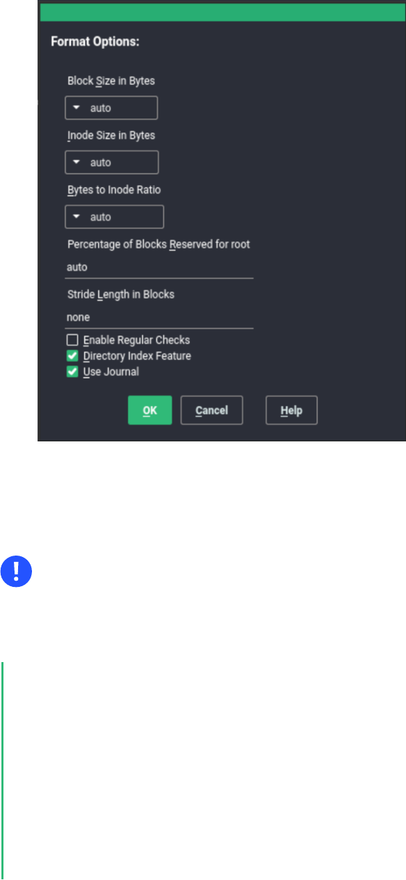
During installation with YaST: Pass the inode size and bytes-per-inode ratio values when
you create a new Ext4 le system during the installation. In the Expert Partitioner, select the
partition, click Edit. Under Formatting Options, select Format deviceExt4, then click Options.
In the Format options dialog, select the desired values from the Block Size in Bytes, Bytes-
per-inode, and Inode Size drop-down box.
For example, select 4096 for the Block Size in Bytes drop-down box, select 8192 from the
Bytes per inode drop-down box, select 128 from the Inode Size drop-down box, then click OK.
26 Ext4 file system inode size and number of inodes SLES 15 SP5
1.6.3 Upgrading to Ext4
Important: Backup of data
Back up all data on the le system before performing any update of your le system.
PROCEDURE1.3:UPGRADING TO EXT4
1.
To upgrade from Ext2 or Ext3, you must enable the following:
FEATURES REQUIRED BY EXT4
extents
contiguous blocks on the hard disk that are used to keep les close together and
prevent fragmentation
unint_bg
lazy inode table initialization
27 Upgrading to Ext4 SLES 15 SP5

dir_index
hashed b-tree lookups for large directories
on Ext2: as_journal
enable journaling on your Ext2 le system.
To enable the features, run:
on Ext3:
# tune2fs -O extents,uninit_bg,dir_index DEVICE_NAME
on Ext2:
# tune2fs -O extents,uninit_bg,dir_index,has_journal DEVICE_NAME
2.
As root edit the /etc/fstab le: change the ext3 or ext2 record to ext4 . The change
takes effect after the next reboot.
3.
To boot a le system that is set up on an ext4 partition, add the modules: ext4 and jbd
in the initramfs . Open or create /etc/dracut.conf.d/filesystem.conf and add the
following line:
force_drivers+=" ext4 jbd"
You need to overwrite the existing dracut initramfs by running:
dracut -f
4.
Reboot your system.
1.7 ReiserFS
ReiserFS support was completely removed with SUSE Linux Enterprise Server 15. To migrate
your existing partitions to Btrfs, refer to Section1.2.3, “Migration from ReiserFS and ext file systems
to Btrfs”.
28 ReiserFS SLES 15 SP5

1.8 OpenZFS and ZFS
Neither the OpenZFS nor ZFS le systems are supported by SUSE. Although ZFS was originally
released by Sun under an open source license, the current Oracle Solaris ZFS is now closed
source, and therefore cannot be used by SUSE. OpenZFS (based on the original ZFS) is under
the CDDL license that is incompatible with the GPL license and therefore cannot be included in
our kernels. However, Btrfs provides an excellent alternative to OpenZFS with a similar design
philosophy and is fully supported by SUSE.
1.9 tmpfs
tmpfs is a RAM-based virtual memory le system. The le system is temporary, which means no
les are stored on the hard disk, and when the le system is unmounted, all data is discarded.```
Data in this le system is stored in the kernel internal cache. The needed kernel cache space
can grow or shrink.
The le system has the following characteristics:
Very fast access to les.
When swap is enabled for the tmpfs mount, unused data is swapped.
You can change the le system size during the mount -o remount operation without
losing data. However, you cannot resize to the value lower than its current usage.
tmpfs supports Transparent HugePage Support (THP).
For more information, you can refer to:
the kernel documentation (https://www.kernel.org/doc/html/latest/filesystems/tmpfs.html)
man tmpfs
1.10 Other supported file systems
Table1.1, “File system types in Linux” summarizes some other le systems supported by Linux. They
are supported mainly to ensure compatibility and interchange of data with different kinds of
media or foreign operating systems.
29 OpenZFS and ZFS SLES 15 SP5

TABLE1.1:FILE SYSTEM TYPES IN LINUX
File System Type Description
iso9660 Standard le system on CD-ROMs.
msdos fat , the le system originally used by DOS, is today used by vari-
ous operating systems.
nfs Network File System: Here, data can be stored on any machine in a
network and access might be granted via a network.
ntfs WindowsNT le system supported only with read-only access. The
FUSE client ntfs-3g provides the access.
OverlayFS File system combines multiple different underlying mount points in-
to one. It is used mainly on transactional-update systems and with
containers.
exfat File system optimized for use with ash memory, such as USB ash
drives and SD cards.
Squashfs A compressed read-only le system. The le system compresses les,
inodes and directories, and supports block sizes from 4 KiB up to 1
MiB for greater compression.
smbfs Server Message Block is used by products such as Windows to enable
le access over a network. Includes support for cifs — a network
le system client for mounting SMB/CIFS shares.
ufs Used by BSD, SunOS and NextStep. Only supported in read-only
mode.
vfat Virtual FAT: Extension of the fat le system (supports long le
names).
30 Other supported file systems SLES 15 SP5

1.11 Blocked file systems
Due to security reasons, some le systems have been blocked from automatic mounting. These
le systems are usually not maintained anymore and are not in common use. However, the
kernel module for this le system can be loaded, because the in-kernel API is still compatible.
A combination of user-mountable le systems and the automatic mounting of le systems on
removable devices could result in the situation where unprivileged users might trigger the au-
tomatic loading of kernel modules, and the removable devices could store potentially malicious
data.
To get a list of le systems that are not allowed to be mounted automatically, run the following
command:
> sudo rpm -ql suse-module-tools | sed -nE 's/.*blacklist_fs-(.*)\.conf/\1/p'
If you try to mount a device with a blocked le system using the mount command, the command
outputs an error message, for example:
mount: /mnt/mx: unknown filesystem type 'minix' (hint: possibly blacklisted, see
mount(8)).
Even though a le system cannot be mounted automatically, you can load the corresponding
kernel module for the le system directly using modprobe :
> sudo modprobe FILESYSTEM
For example, for the cramfs le system, the output looks as follows:
unblacklist: loading cramfs file system module
unblacklist: Do you want to un-blacklist cramfs permanently (<y>es/<n>o/n<e>ver)? y
unblacklist: cramfs un-blacklisted by creating /etc/modprobe.d/60-blacklist_fs-
cramfs.conf
Here you have the following options:
y
es
The module will be loaded and removed from the blacklist. Therefore, the module will be
loaded automatically in future without any other prompt.
The configuration le /etc/modprobe.d/60-blacklist_fs-${MODULE}.conf is created.
Remove the le to undo the changes you performed.
n
o
The module will be loaded, but it is not removed from the blacklist. Therefore, on a next
module loading you will see the prompt above again.
31 Blocked file systems SLES 15 SP5

e
ver
The module will be loaded, but autoloading is disabled even for future use, and the prompt
will no longer be displayed.
The configuration le /etc/modprobe.d/60-blacklist_fs-${MODULE}.conf is created.
Remove the le to undo the changes you performed.
Ctrl
–
c
This option is used to interrupt the module loading.
1.12 Large file support in Linux
Originally, Linux supported a maximum le size of 2GiB (2
31
bytes). Unless a le system comes
with large le support, the maximum le size on a 32-bit system is 2 GiB.
Currently, all our standard le systems have LFS (large le support), which gives a maximum
le size of 2
63
bytes in theory. Table1.2, “Maximum sizes of files and file systems (on-disk format, 4
KiB block size)” offers an overview of the current on-disk format limitations of Linux les and le
systems. The numbers in the table assume that the le systems are using 4 KiB block size, which
is a common standard. When using different block sizes, the results are different. The maximum
le sizes in Table1.2, “Maximum sizes of files and file systems (on-disk format, 4 KiB block size)” can be
larger than the le system's actual size when using sparse blocks.
Note: Binary multiples
In this document: 1024 Bytes = 1 KiB; 1024 KiB = 1 MiB; 1024 MiB = 1 GiB; 1024 GiB
= 1 TiB; 1024 TiB = 1 PiB; 1024 PiB = 1 EiB (see also NIST: Prefixes for Binary Multiples
(https://physics.nist.gov/cuu/Units/binary.html) .
TABLE1.2:MAXIMUM SIZES OF FILES AND FILE SYSTEMS (ON-DISK FORMAT, 4 KIB BLOCK SIZE)
File System (4 KiB Block
Size)
Maximum File System Size Maximum File Size
Btrfs 16 EiB 16 EiB
Ext3 16 TiB 2 TiB
Ext4 1 EiB 16 TiB
32 Large file support in Linux SLES 15 SP5

File System (4 KiB Block
Size)
Maximum File System Size Maximum File Size
OCFS2 (a cluster-aware le
system available in SLEHA)
16 TiB 1 EiB
XFS 16 EiB 8 EiB
NFSv2 (client side) 8 EiB 2 GiB
NFSv3/NFSv4 (client side) 8 EiB 8 EiB
Important: Limitations
Table1.2, “Maximum sizes of files and file systems (on-disk format, 4 KiB block size)” describes
the limitations regarding the on-disk format. The Linux kernel imposes its own limits on
the size of les and le systems handled by it. These are as follows:
File size
On 32-bit systems, les cannot exceed 2 TiB (2
41
bytes).
File system size
File systems can be up to 2
73
bytes in size. However, this limit is still out of reach
for the currently available hardware.
1.13 Linux kernel storage limitations
Table1.3, “Storage limitations” summarizes the kernel limits for storage associated with SUSE Linux
Enterprise Server.
TABLE1.3:STORAGE LIMITATIONS
Storage Feature Limitation
Maximum number of LUNs supported 16384 LUNs per target.
Maximum number of paths per single LUN No limit by default. Each path is treated as a
normal LUN.
33 Linux kernel storage limitations SLES 15 SP5

Storage Feature Limitation
The actual limit is given by the number of
LUNs per target and the number of targets
per HBA (16777215 for a Fibre Channel
HBA).
Maximum number of HBAs Unlimited. The actual limit is determined by
the amount of PCI slots of the system.
Maximum number of paths with de-
vice-mapper-multipath (in total) per operat-
ing system
Approximately 1024. The actual number
depends on the length of the device num-
ber strings for each multipath device. It
is a compile-time variable within multi-
path-tools, which can be raised if this limit
poses a problem.
Maximum size per block device Up to 8 EiB.
1.14 Freeing unused file system blocks
On solid-state drives (SSDs) and thinly provisioned volumes, it is useful to trim blocks that are
not in use by the le system. SUSE Linux Enterprise Server fully supports unmap and TRIM
operations on all le systems supporting them.
There are two types of commonly used TRIM—online TRIM and periodic TRIM . The most suit-
able way of trimming devices depends on your use case. In general, it is recommended to use
periodic TRIM, especially if the device has enough free blocks. If the device is often near its full
capacity, online TRIM is preferable.
Important: TRIM support on devices
Always verify that your device supports the TRIM operation before you attempt to use
it. Otherwise, you might lose your data on that device. To verify the TRIM support, run
the command:
> sudo lsblk --discard
34 Freeing unused file system blocks SLES 15 SP5

The command outputs information about all available block devices. If the values of the
columns DISC-GRAN and DISC-MAX are non-zero, the device supports the TRIM opera-
tion.
1.14.1 Periodic TRIM
Periodic TRIM is handled by the fstrim command invoked by systemd on a regular basis.
You can also run the command manually.
To schedule periodic TRIM, enable the fstrim.timer as follows:
> sudo systemctl enable fstrim.timer
systemd creates a unit le in /usr/lib/systemd/system . By default, the service runs once
a week, which is usually sufficient. However, you can change the frequency by configuring the
OnCalendar option to a required value.
The default behaviour of fstrim is to discard all blocks in the le system. You can use options
when invoking the command to modify this behaviour. For example, you can pass the offset
option to define the place where to start the trimming procedure. For details, see man fstrim .
The fstrim command can perform trimming on all devices stored in the /etc/fstab le,
which support the TRIM operation—use the -A option when invoking the command for this
purpose.
To disable the trimming of a particular device, add the option X-fstrim.notrim to the /etc/
fstab le as follows:
UID=83df497d-bd6d-48a3-9275-37c0e3c8dc74 / btrfs defaults,X-fstrim.notrim
0 0
1.14.2 Online TRIM
Online TRIM of a device is performed each time data is written to the device.
To enable online TRIM on a device, add the discard option to the /etc/fstab le as follows:
UID=83df497d-bd6d-48a3-9275-37c0e3c8dc74 / btrfs defaults,discard
35 Periodic TRIM SLES 15 SP5

Alternatively, on the Ext4 le system you can use the tune2fs command to set the discard
option in /etc/fstab :
> sudo tune2fs -o discard DEVICE
The discard option is also added to /etc/fstab in case the device was mounted by mount
with the discard option:
> sudo mount -o discard DEVICE
Note: Drawbacks of online TRIM
Using the discard option may decrease the lifetime of some lower-quality SSD devices.
Online TRIM can also impact the performance of the device, for example, if a larger
amount of data is deleted. In this situation, an erase block might be reallocated, and
shortly afterwards, the same erase block might be marked as unused again.
1.15 Troubleshooting file systems
This section describes some known issues and possible solutions for le systems.
1.15.1 Btrfs error: no space is left on device
The root ( / ) partition using the Btrfs le system stops accepting data. You receive the error
“ No space left on device ”.
See the following sections for information about possible causes and prevention of this issue.
1.15.1.1 Disk space consumed by Snapper snapshots
If Snapper is running for the Btrfs le system, the “ No space left on device ” problem is
typically caused by having too much data stored as snapshots on your system.
You can remove some snapshots from Snapper, however, the snapshots are not deleted imme-
diately and might not free up as much space as you need.
To delete les from Snapper:
1.
Open a terminal.
36 Troubleshooting file systems SLES 15 SP5

2.
At the command prompt, enter btrfs filesystem show , for example:
> sudo btrfs filesystem show
Label: none uuid: 40123456-cb2c-4678-8b3d-d014d1c78c78
Total devices 1 FS bytes used 20.00GB
devid 1 size 20.00GB used 20.00GB path /dev/sda3
3.
Enter
> sudo btrfs fi balance start MOUNTPOINT -dusage=5
This command attempts to relocate data in empty or near-empty data chunks, allowing
the space to be reclaimed and reassigned to metadata. This can take a while (many hours
for 1TB) although the system is otherwise usable during this time.
4.
List the snapshots in Snapper. Enter
> sudo snapper -c root list
5.
Delete one or more snapshots from Snapper. Enter
> sudo snapper -c root delete SNAPSHOT_NUMBER(S)
Ensure that you delete the oldest snapshots rst. The older a snapshot is, the more disk
space it occupies.
To help prevent this problem, you can change the Snapper cleanup algorithms. See Book “Admin-
istration Guide”, Chapter10 “System recovery and snapshot management with Snapper”, Section10.6.1.2
“Cleanup algorithms” for details. The configuration values controlling snapshot cleanup are EMP-
TY_* , NUMBER_* , and TIMELINE_* .
If you use Snapper with Btrfs on the le system disk, it is advisable to reserve twice the amount
of disk space than the standard storage proposal. The YaST Partitioner automatically proposes
twice the standard disk space in the Btrfs storage proposal for the root le system.
1.15.1.2 Disk space consumed by log, crash, and cache files
If the system disk is filling up with data, you can try deleting les from /var/log , /var/crash ,
/var/lib/systemd/coredump and /var/cache .
37 Btrfs error: no space is left on device SLES 15 SP5

The Btrfs root le system subvolumes /var/log , /var/crash and /var/cache can use all
of the available disk space during normal operation, and cause a system malfunction. To help
avoid this situation, SUSE Linux Enterprise Server offers Btrfs quota support for subvolumes.
See Section1.2.5, “Btrfs quota support for subvolumes” for details.
On test and development machines, especially if you have frequent crashes of applications,
you may also want to have a look at /var/lib/systemd/coredump where the core dumps are
stored.
1.15.2 Btrfs: balancing data across devices
The btrfs balance command is part of the btrfs-progs package. It balances block groups
on Btrfs le systems in the following example situations:
Assume you have a 1TB drive with 600GB used by data and you add another 1TB drive.
The balancing will theoretically result in having 300GB of used space on each drive.
You have a lot of near-empty chunks on a device. Their space will not be available until
the balancing has cleared those chunks.
You need to compact half-empty block group based on the percentage of their usage. The
following command will balance block groups whose usage is 5% or less:
> sudo btrfs balance start -dusage=5 /
Tip
The /usr/lib/systemd/system/btrfs-balance.timer timer takes care of clean-
ing up unused block groups on a monthly basis.
You need to clear out non-full portions of block devices and spread data more evenly.
You need to migrate data between different RAID types. For example, to convert data on
a set of disks from RAID1 to RAID5, run the following command:
> sudo btrfs balance start -dprofiles=raid1,convert=raid5 /
38 Btrfs: balancing data across devices SLES 15 SP5

Tip
To ne-tune the default behavior of balancing data on Btrfs le systems—for example,
how frequently or which mount points to balance— inspect and customize /etc/syscon-
fig/btrfsmaintenance . The relevant options start with BTRFS_BALANCE_ .
For details about the btrfs balance command usage, see its manual pages ( man 8 btrfs-
balance ).
1.15.3 No defragmentation on SSDs
Linux le systems contain mechanisms to avoid data fragmentation and usually it is not neces-
sary to defragment. However, there are use cases, where data fragmentation cannot be avoided
and where defragmenting the hard disk significantly improves the performance.
This only applies to conventional hard disks. On solid state disks (SSDs) which use ash memory
to store data, the rmware provides an algorithm that determines to which chips the data is
written. Data is usually spread all over the device. Therefore defragmenting an SSD does not
have the desired effect and will reduce the lifespan of an SSD by writing unnecessary data.
For the reasons mentioned above, SUSE explicitly recommends not to defragment SSDs. Some
vendors also warn about defragmenting solid state disks. This includes, but it is not limited to
the following:
HPE 3PAR StoreServ All-Flash
HPE 3PAR StoreServ Converged Flash
1.16 More information
Each of the le system projects described above maintains its own home page on which to nd
mailing list information, further documentation, and FAQs:
The Btrfs Wiki on Kernel.org: https://btrfs.wiki.kernel.org/
E2fsprogs: Ext2/3/4 File System Utilities: https://e2fsprogs.sourceforge.net/
The OCFS2 Project: https://oss.oracle.com/projects/ocfs2/
39 No defragmentation on SSDs SLES 15 SP5


2 Resizing file systems
Resizing le systems—not to be confused with resizing partitions or volumes—can be used to
make space available on physical volumes or to use additional space available on a physical
volume.
2.1 Use cases
It is strongly recommended to use the YaST Partitioner to resize partitions or logical volumes.
When doing so, the le system will automatically be adjusted to the new size of the partition
or volume. However, there are some cases where you need to resize the le system manually,
because they are not supported by YaST:
After having resized a virtual disk of a VM Guest.
After having resized a volume from a network-attached storage.
After having manually resized partitions (for example by using fdisk or parted ) or
logical volumes (for example by using lvresize ).
When wanting to shrink Btrfs le systems (as of SUSE Linux Enterprise Server 12, YaST
only supports growing Btrfs le systems).
2.2 Guidelines for resizing
Resizing any le system involves some risks that can potentially result in losing data.
Warning: Back up your data
To avoid data loss, ensure that you back up your data before you begin any resizing task.
Consider the following guidelines when planning to resize a le system.
41 Use cases SLES 15 SP5

2.2.1 File systems that support resizing
The le system must support resizing to take advantage of increases in available space for the
volume. In SUSE Linux Enterprise Server, le system resizing utilities are available for le sys-
tems Ext2, Ext3, and Ext4. The utilities support increasing and decreasing the size as follows:
TABLE2.1:FILE SYSTEM SUPPORT FOR RESIZING
File System Utility Increase Size
(Grow)
Decrease Size
(Shrink)
Btrfs btrfs filesystem
resize
Online Online
XFS xfs_growfs Online Not supported
Ext2 resize2fs Online or offline Offline only
Ext3 resize2fs Online or offline Offline only
Ext4 resize2fs Online or offline Offline only
2.2.2 Increasing the size of a file system
You can grow a le system to the maximum space available on the device, or specify an exact
size. Ensure that you grow the size of the device or logical volume before you attempt to increase
the size of the le system.
When specifying an exact size for the le system, ensure that the new size satisfies the following
conditions:
The new size must be greater than the size of the existing data; otherwise, data loss occurs.
The new size must be equal to or less than the current device size because the le system
size cannot extend beyond the space available.
42 File systems that support resizing SLES 15 SP5

2.2.3 Decreasing the size of a file system
When decreasing the size of the le system on a device, ensure that the new size satisfies the
following conditions:
The new size must be greater than the size of the existing data; otherwise, data loss occurs.
The new size must be equal to or less than the current device size because the le system
size cannot extend beyond the space available.
If you plan to also decrease the size of the logical volume that holds the le system, ensure that
you decrease the size of the le system before you attempt to decrease the size of the device
or logical volume.
Important: XFS
Decreasing the size of a le system formatted with XFS is not possible, since such a feature
is not supported by XFS.
2.3 Changing the size of a Btrfs file system
The size of a Btrfs le system can be changed by using the btrfs filesystem resize command
when the le system is mounted. Increasing and decreasing the size are both supported while
the le system is mounted.
1.
Open a terminal.
2.
Make sure the le system you want to change is mounted.
3.
Change the size of the le system using the btrfs filesystem resize command with
one of the following methods:
To extend the le system size to the maximum available size of the device, enter
> sudo btrfs filesystem resize max /mnt
To extend the le system to a specific size, enter
> sudo btrfs filesystem resize SIZE /mnt
43 Decreasing the size of a file system SLES 15 SP5

Replace SIZE with the desired size in bytes. You can also specify units on the value,
such as 50000K (kilobytes), 250M (megabytes), or 2G (gigabytes). Alternatively, you
can specify an increase or decrease to the current size by prefixing the value with a
plus ( + ) or a minus ( - ) sign, respectively:
> sudo btrfs filesystem resize +SIZE /mnt
sudo btrfs filesystem resize -SIZE /mnt
4.
Check the effect of the resize on the mounted le system by entering
> df -h
The Disk Free ( df ) command shows the total size of the disk, the number of blocks used,
and the number of blocks available on the le system. The -h option prints sizes in hu-
man-readable format, such as 1K, 234M, or 2G.
2.4 Changing the size of an XFS file system
The size of an XFS le system can be increased by using the xfs_growfs command when the
le system is mounted. Reducing the size of an XFS le system is not possible.
1.
Open a terminal.
2.
Make sure the le system you want to change is mounted.
3.
Increase the size of the le system using the xfs_growfs command. The following ex-
ample expands the size of the le system to the maximum value available. See man 8
xfs_growfs for more options.
> sudo xfs_growfs -d /mnt
4.
Check the effect of the resize on the mounted le system by entering
> df -h
The Disk Free ( df ) command shows the total size of the disk, the number of blocks used,
and the number of blocks available on the le system. The -h option prints sizes in hu-
man-readable format, such as 1K, 234M, or 2G.
44 Changing the size of an XFS file system SLES 15 SP5

2.5 Changing the size of an ext2, ext3, or ext4 file
system
The size of Ext2, Ext3, and Ext4 le systems can be increased by using the resize2fs command,
regardless of whether the respective partition is mounted or not. To decrease the size of an Ext
le system it needs to be unmounted.
1.
Open a terminal.
2.
If the le system size should be decreased, unmount it.
3.
Change the size of the le system using one of the following methods:
To extend the le system size to the maximum available size of the device called /
dev/sda1 , enter
> sudo resize2fs /dev/sda1
If a size parameter is not specified, the size defaults to the size of the partition.
To change the le system to a specific size, enter
> sudo resize2fs /dev/sda1 SIZE
The SIZE parameter specifies the requested new size of the le system. If no units are
specified, the unit of the size parameter is the block size of the le system. Optionally,
the size parameter can be suffixed by one of the following unit designations: s for
512 byte sectors; K for kilobytes (1 kilobyte is 1024 bytes); M for megabytes; or
G for gigabytes.
Wait until the resizing is completed before continuing.
4.
If the le system is not mounted, mount it now.
5.
Check the effect of the resize on the mounted le system by entering
> df -h
The Disk Free ( df ) command shows the total size of the disk, the number of blocks used,
and the number of blocks available on the le system. The -h option prints sizes in hu-
man-readable format, such as 1K, 234M, or 2G.
45 Changing the size of an ext2, ext3, or ext4 file system SLES 15 SP5

3 Mounting storage devices
This section gives an overview of which device identificators are used during mounting of de-
vices, and provides details about mounting network storages.
3.1 Understanding UUIDs
A UUID (Universally Unique Identifier) is a 128-bit number for a le system that is unique on
both the local system and across other systems. It is randomly generated with system hardware
information and time stamps as part of its seed. UUIDs are commonly used to uniquely tag
devices.
Using non-persistent “traditional” device names such as /dev/sda1 may render the system
unbootable when adding storage. For example, if root ( / ) is assigned to /dev/sda1 , it might
be reassigned to /dev/sdg1 after a SAN has been attached or additional hard disks have been
applied to the system. In this case the boot loader configuration and the /etc/fstab le need
to be adjusted, otherwise the system will no longer boot.
By default, UUIDs are used in the boot loader and /etc/fstab les for the boot device. The
UUID is a property of the le system and can change if you reformat the drive. Other alternatives
to using UUIDs of device names would be to identify devices by ID or label.
You can also use the UUID as criterion for assembling and activating software RAID devices.
When a RAID is created, the md driver generates a UUID for the device, and stores the value
in the md superblock.
You can nd the UUID for any block device in the /dev/disk/by-uuid directory. For example,
a UUID entry looks like this:
> ls -og /dev/disk/by-uuid/
lrwxrwxrwx 1 10 Dec 5 07:48 e014e482-1c2d-4d09-84ec-61b3aefde77a -> ../../sda1
3.2 Persistent device names with udev
Starting with Linux kernel 2.6, udev provides a user space solution for the dynamic /dev
directory, with persistent device naming. As part of the hotplug system, udev is executed if a
device is added to or removed from the system.
46 Understanding UUIDs SLES 15 SP5

A list of rules is used to match against specific device attributes. The udev rules infrastructure
(defined in the /etc/udev/rules.d directory) provides stable names for all disk devices, re-
gardless of their order of recognition or the connection used for the device. The udev tools
examine every appropriate block device that the kernel creates to apply naming rules based on
certain buses, drive types, or le systems. For information about how to define your own rules
for udev , see Writing udev Rules (https://reactivated.net/writing_udev_rules.html) .
Along with the dynamic kernel-provided device node name, udev maintains classes of persistent
symbolic links pointing to the device in the /dev/disk directory, which is further categorized
by the by-id , by-label , by-path , and by-uuid subdirectories.
Note: UUID generators
Other programs besides udev , such as LVM or md , might also generate UUIDs, but they
are not listed in /dev/disk .
For more information about using udev for managing devices, see Book “Administration Guide”,
Chapter29 “Dynamic kernel device management with udev”.
For more information about udev commands, see man 7 udev .
3.3 Mounting network storage devices
Some types of storage devices require the network to be configured and available before sys-
temd.mount starts to mount the devices. To postpone mounting of these types of devices, add
the _netdev and x-systemd.requires=iscsi.service options to the /etc/fstab le for
each particular network storage device. An example follows:
mars.example.org:/nfsexport /shared nfs defaults,_netdev,x-
systemd.requires=iscsi.service 0 0
Do not use the nofail option as booting of the machine continues without waiting for the
particular storage device to be successfully mounted.
47 Mounting network storage devices SLES 15 SP5

4 Multi-tier caching for block device operations
A multi-tier cache is a replicated/distributed cache that consists of at least two tiers: one is
represented by slower but cheaper rotational block devices (hard disks), while the other is more
expensive but performs faster data operations (for example SSD ash disks).
SUSE Linux Enterprise Server implements two different solutions for caching between ash and
rotational devices: bcache and lvmcache .
4.1 General terminology
This section explains several terms often used when describing cache related features:
Migration
Movement of the primary copy of a logical block from one device to the other.
Promotion
Migration from the slow device to the fast device.
Demotion
Migration from the fast device to the slow device.
Origin device
The big and slower block device. It always contains a copy of the logical block, which may
be out of date or kept in synchronization with the copy on the cache device (depending
on policy).
Cache device
The small and faster block device.
Metadata device
A small device that records which blocks are in the cache, which are dirty, and extra hints
for use by the policy object. This information could be put on the cache device as well,
but having it separate allows the volume manager to configure it differently, for example
as a mirror for extra robustness. The metadata device may only be used by a single cache
device.
48 General terminology SLES 15 SP5
Dirty block
If some process writes to a block of data which is placed in the cache, the cached block
is marked as dirty because it was overwritten in the cache and needs to be written back
to the original device.
Cache miss
A request for I/O operations is pointed to the cached device's cache rst. If it cannot nd
the requested values, it looks in the device itself, which is slow. This is called a cache miss.
Cache hit
When a requested value is found in the cached device's cache, it is served fast. This is
called a cache hit.
Cold cache
Cache that holds no values (is empty) and causes cache misses. As the cached block device
operations progress, it gets lled with data and becomes warm.
Warm cache
Cache that already holds some values and is likely to result in cache hits.
4.2 Caching modes
Following are the basic caching modes that multi-tier caches use: write-back, write-through, write-
around and pass-through.
write-back
Data written to a block that is cached go to the cache only, and the block is marked dirty.
This is the default caching mode.
write-through
Writing to a cached block will not complete until it has hit both the origin and cache
devices. Clean blocks remain clean with write-through cache.
write-around
A similar technique to write-through cache, but write I/O is written directly to a permanent
storage, bypassing the cache. This can prevent the cache being flooded with write I/O that
will not subsequently be re-read, but the disadvantage is that a read request for recently
written data will create a 'cache miss' and needs to be read from slower bulk storage and
experience higher latency.
49 Caching modes SLES 15 SP5

pass-through
To enable the pass-through mode, the cache needs to be clean. Reading is served from the
origin device bypassing the cache. Writing is forwarded to the origin device and 'invali-
dates' the cache block. Pass-through allows a cache device activation without having to
care about data coherency, which is maintained. The cache will gradually become cold as
writing takes place. If you can verify the coherency of the cache later, or establish it by
using the invalidate_cblocks message, you can switch the cache device to write-through
or write-back mode while it is still warm. Otherwise, you can discard the cache contents
before switching to the desired caching mode.
4.3 bcache
bcache is a Linux kernel block layer cache. It allows one or more fast disk drives (such as SSDs)
to act as a cache for one or more slower hard disks. bcache supports write-through and write-
back, and is independent of the le system used. By default it caches random reads and writes
only, which SSDs excel at. It is suitable for desktops, servers, and high end storage arrays as well.
4.3.1 Main features
A single cache device can be used to cache an arbitrary number of backing devices. Backing
devices can be attached and detached at runtime, while mounted and in use.
Recovers from unclean shutdowns—writes are not completed until the cache is consistent
with regard to the backing device.
Throttles traffic to the SSD if it becomes congested.
Highly efficient write-back implementation. Dirty data is always written out in sorted or-
der.
Stable and reliable—in production use.
4.3.2 Setting up a bcache device
This section describes steps to set up and manage a bcache device.
50 bcache SLES 15 SP5

1.
Install the bcache-tools package:
> sudo zypper in bcache-tools
2.
Create a backing device (typically a mechanical drive). The backing device can be a whole
device, a partition, or any other standard block device.
> sudo make-bcache -B /dev/sdb
3.
Create a cache device (typically an SSD disk).
> sudo make-bcache -C /dev/sdc
In this example, the default block and bucket sizes of 512 B and 128 KB are used. The
block size should match the backing device's sector size which will usually be either 512
or 4k. The bucket size should match the erase block size of the caching device with the
intention of reducing write amplification. For example, using a hard disk with 4k sectors
and an SSD with an erase block size of 2 MB this command would look as follows:
sudo make-bcache --block 4k --bucket 2M -C /dev/sdc
Tip: Multi-device support
make-bcache can prepare and register multiple backing devices and a cache device
at the same time. In this case you do not need to manually attach the cache device
to the backing device afterward:
> sudo make-bcache -B /dev/sda /dev/sdb -C /dev/sdc
4.
bcache devices show up as
/dev/bcacheN
and as
/dev/bcache/by-uuid/UUID
/dev/bcache/by-label/LABEL
You can normally format and mount bcache devices as usual:
> sudo mkfs.ext4 /dev/bcache0
51 Setting up a bcache device SLES 15 SP5

> sudo mount /dev/bcache0 /mnt
You can control bcache devices through sysfs at /sys/block/bcacheN/bcache .
5.
After both the cache and backing devices are registered, you need to attach the backing
device to the related cache set to enable caching:
> echo CACHE_SET_UUID > /sys/block/bcache0/bcache/attach
where CACHE_SET_UUID is found in /sys/fs/bcache .
6.
By default bcache uses a pass-through caching mode. To change it to for example write-
back, run
> echo writeback > /sys/block/bcache0/bcache/cache_mode
4.3.3 bcache configuration using sysfs
bcache devices use the sysfs interface to store their runtime configuration values. This way
you can change bcache backing and cache disks' behavior or see their usage statistics.
For the complete list of bcache sysfs parameters, see the contents of the /usr/src/lin-
ux/Documentation/bcache.txt le, mainly the SYSFS - BACKING DEVICE , SYSFS - BACK-
ING DEVICE STATS , and SYSFS - CACHE DEVICE sections.
4.4 lvmcache
lvmcache is a caching mechanism consisting of logical volumes (LVs). It uses the dm-cache
kernel driver and supports write-through (default) and write-back caching modes. lvmcache
improves performance of a large and slow LV by dynamically migrating some of its data to a
faster and smaller LV. For more information on LVM, see PartII, “Logical volumes (LVM)”.
LVM refers to the small, fast LV as a cache pool LV. The large, slow LV is called the origin LV.
Because of requirements from dm-cache, LVM further splits the cache pool LV into two devices:
the cache data LV and cache metadata LV. The cache data LV is where copies of data blocks
are kept from the origin LV to increase speed. The cache metadata LV holds the accounting
information that specifies where data blocks are stored.
52 bcache configuration using sysfs SLES 15 SP5

4.4.1 Configuring lvmcache
This section describes steps to create and configure LVM based caching.
1.
Create the origin LV. Create a new LV or use an existing LV to become the origin LV:
> sudo lvcreate -n ORIGIN_LV -L 100G vg /dev/SLOW_DEV
2.
Create the cache data LV. This LV will hold data blocks from the origin LV. The size of this
LV is the size of the cache and will be reported as the size of the cache pool LV.
> sudo lvcreate -n CACHE_DATA_LV -L 10G vg /dev/FAST
3.
Create the cache metadata LV. This LV will hold cache pool metadata. The size of this LV
should be approximately 1000 times smaller than the cache data LV, with a minimum
size of 8MB.
> sudo lvcreate -n CACHE_METADATA_LV -L 12M vg /dev/FAST
List the volumes you have created so far:
> sudo lvs -a vg
LV VG Attr LSize Pool Origin
cache_data_lv vg -wi-a----- 10.00g
cache_metadata_lv vg -wi-a----- 12.00m
origin_lv vg -wi-a----- 100.00g
4.
Create a cache pool LV. Combine the data and metadata LVs into a cache pool LV. You can
set the cache pool LV's behavior at the same time.
CACHE_POOL_LV takes the name of CACHE_DATA_LV .
CACHE_DATA_LV is renamed to CACHE_DATA_LV _cdata and becomes hidden.
CACHE_META_LV is renamed to CACHE_DATA_LV _cmeta and becomes hidden.
> sudo lvconvert --type cache-pool \
--poolmetadata vg/cache_metadata_lv vg/cache_data_lv
> sudo lvs -a vg
LV VG Attr LSize Pool Origin
cache_data_lv vg Cwi---C--- 10.00g
[cache_data_lv_cdata] vg Cwi------- 10.00g
[cache_data_lv_cmeta] vg ewi------- 12.00m
origin_lv vg -wi-a----- 100.00g
5.
Create a cache LV. Create a cache LV by linking the cache pool LV to the origin LV.
53 Configuring lvmcache SLES 15 SP5

The user accessible cache LV takes the name of the origin LV, while the origin LV becomes
a hidden LV renamed to ORIGIN_LV _corig.
CacheLV takes the name of ORIGIN_LV .
ORIGIN_LV is renamed to ORIGIN_LV _corig and becomes hidden.
> sudo lvconvert --type cache --cachepool vg/cache_data_lv vg/origin_lv
> sudo lvs -a vg
LV VG Attr LSize Pool Origin
cache_data_lv vg Cwi---C--- 10.00g
[cache_data_lv_cdata] vg Cwi-ao---- 10.00g
[cache_data_lv_cmeta] vg ewi-ao---- 12.00m
origin_lv vg Cwi-a-C--- 100.00g cache_data_lv [origin_lv_corig]
[origin_lv_corig] vg -wi-ao---- 100.00g
4.4.2 Removing a cache pool
There are several ways to turn o the LV cache.
4.4.2.1 Detach a cache pool LV from a cache LV
You can disconnect a cache pool LV from a cache LV, leaving an unused cache pool LV and an
uncached origin LV. Data are written back from the cache pool to the origin LV when necessary.
> sudo lvconvert --splitcache vg/origin_lv
4.4.2.2 Removing a cache pool LV without removing its origin LV
This writes back data from the cache pool to the origin LV when necessary, then removes the
cache pool LV, leaving the uncached origin LV.
> sudo lvremove vg/cache_data_lv
An alternative command that also disconnects the cache pool from the cache LV, and deletes
the cache pool:
> sudo lvconvert --uncache vg/origin_lv
54 Removing a cache pool SLES 15 SP5

4.4.2.3 Removing both the origin LV and the cache pool LV
Removing a cache LV removes both the origin LV and the linked cache pool LV.
> sudo lvremove vg/origin_lv
4.4.2.4 More information
You can nd more lvmcache related topics, such as supported cache modes, redundant sub-
logical volumes, cache policy, or converting existing LVs to cache types, in the lvmcache man-
ual page ( man 7 lvmcache ).
55 Removing a cache pool SLES 15 SP5

5 LVM configuration
This chapter describes the principles behind Logical Volume Manager (LVM) and its
basic features that make it useful under many circumstances. The YaST LVM config-
uration can be reached from the YaST Expert Partitioner. This partitioning tool en-
ables you to edit and delete existing partitions and create new ones that should be
used with LVM.
Warning: Risks
Using LVM might be associated with increased risk, such as data loss. Risks also include
application crashes, power failures, and faulty commands. Save your data before imple-
menting LVM or reconfiguring volumes. Never work without a backup.
5.1 Understanding the logical volume manager
LVM enables flexible distribution of hard disk space over several physical volumes (hard disks,
partitions, LUNs). It was developed because the need to change the segmentation of hard disk
space might arise only after the initial partitioning has already been done during installation.
Because it is difficult to modify partitions on a running system, LVM provides a virtual pool
(volume group or VG) of storage space from which logical volumes (LVs) can be created as
needed. The operating system accesses these LVs instead of the physical partitions. Volume
groups can span more than one disk, so that several disks or parts of them can constitute one
single VG. In this way, LVM provides a kind of abstraction from the physical disk space that
allows its segmentation to be changed in a much easier and safer way than through physical
repartitioning.
Figure5.1, “Physical partitioning versus LVM” compares physical partitioning (left) with LVM seg-
mentation (right). On the left side, one single disk has been divided into three physical partitions
(PART), each with a mount point (MP) assigned so that the operating system can access them.
On the right side, two disks have been divided into two and three physical partitions each. Two
LVM volume groups (VG1 and VG2) have been defined. VG1 contains two partitions from
DISK1 and one from DISK2. VG2 contains the remaining two partitions from DISK2.
57 Understanding the logical volume manager SLES 15 SP5

DISK
DISK 1
DISK 2
PART PART PART PART PART
VG 2
VG 1
LV 1
LV 2
LV 3
LV 4
MP MP MP MP MP MP MP
PART PART PART
FIGURE5.1:PHYSICAL PARTITIONING VERSUS LVM
In LVM, the physical disk partitions that are incorporated in a volume group are called physical
volumes (PVs). Within the volume groups in Figure 5.1, “Physical partitioning versus LVM”, four
logical volumes (LV1 through LV4) have been defined, which can be used by the operating
system via the associated mount points (MP). The border between different logical volumes need
not be aligned with any partition border. See the border between LV1 and LV2 in this example.
LVM features:
Several hard disks or partitions can be combined in a large logical volume.
Provided the configuration is suitable, an LV (such as /usr ) can be enlarged when the
free space is exhausted.
Using LVM, it is possible to add hard disks or LVs in a running system. However, this
requires hotpluggable hardware that is capable of such actions.
It is possible to activate a striping mode that distributes the data stream of a logical volume
over several physical volumes. If these physical volumes reside on different disks, this can
improve the reading and writing performance like RAID0.
The snapshot feature enables consistent backups (especially for servers) in the running
system.
Note: LVM and RAID
Even though LVM also supports RAID levels 0, 1, 4, 5 and 6, we recommend using mdraid
(see Chapter7, Software RAID configuration). However, LVM works ne with RAID0 and 1,
as RAID0 is similar to common logical volume management (individual logical blocks are
58 Understanding the logical volume manager SLES 15 SP5

mapped onto blocks on the physical devices). LVM used on top of RAID1 can keep track
of mirror synchronization and is fully able to manage the synchronization process. With
higher RAID levels you need a management daemon that monitors the states of attached
disks and can inform administrators if there is a problem in the disk array. LVM includes
such a daemon, but in exceptional situations such as a device failure, the daemon does
not work properly.
Warning: IBMZ: LVM root file system
If you configure the system with a root le system on LVM or software RAID array, you
must place /boot on a separate, non-LVM or non-RAID partition, otherwise the system
will fail to boot. The recommended size for such a partition is 500MB and the recom-
mended le system is Ext4.
With these features, using LVM already makes sense for heavily-used home PCs or small servers.
If you have a growing data stock, as in the case of databases, music archives, or user directo-
ries, LVM is especially useful. It allows le systems that are larger than the physical hard disk.
However, keep in mind that working with LVM is different from working with conventional
partitions.
You can manage new or existing LVM storage objects by using the YaST Partitioner. Instructions
and further information about configuring LVM are available in the official LVM HOWTO (https://
tldp.org/HOWTO/LVM-HOWTO/) .
5.2 Creating volume groups
An LVM volume group (VG) organizes the Linux LVM partitions into a logical pool of space. You
can carve out logical volumes from the available space in the group. The Linux LVM partitions
in a group can be on the same or different disks. You can add partitions or entire disks to expand
the size of the group.
To use an entire disk, it must not contain any partitions. When using partitions, they must not
be mounted. YaST will automatically change their partition type to 0x8E Linux LVM when
adding them to a VG.
1.
Launch YaST and open the Partitioner.
59 Creating volume groups SLES 15 SP5

2.
In case you need to reconfigure your existing partitioning setup, proceed as follows. Re-
fer to Book “Deployment Guide”, Chapter10 “Expert Partitioner”, Section10.1 “Using the Expert
Partitioner” for details. Skip this step if you only want to use unused disks or partitions
that already exist.
Warning: Physical volumes on unpartitioned disks
You can use an unpartitioned disk as a physical volume (PV) if that disk is not the
one where the operating system is installed and from which it boots.
As unpartitioned disks appear as unused at the system level, they can easily be
overwritten or wrongly accessed.
a.
To use an entire hard disk that already contains partitions, delete all partitions on
that disk.
b.
To use a partition that is currently mounted, unmount it.
3.
In the left panel, select Volume Management.
A list of existing Volume Groups opens in the right panel.
4.
At the lower left of the Volume Management page, click Add Volume Group.
60 Creating volume groups SLES 15 SP5

5.
Define the volume group as follows:
a.
Specify the Volume Group Name.
If you are creating a volume group at install time, the name system is suggested for
a volume group that will contain the SUSE Linux Enterprise Server system les.
b.
Specify the Physical Extent Size.
The Physical Extent Size defines the size of a physical block in the volume group. All
the disk space in a volume group is handled in chunks of this size. Values can be
from 1 KB to 16 GB in powers of 2. This value is normally set to 4MB.
In LVM1, a 4 MB physical extent allowed a maximum LV size of 256 GB because
it supports only up to 65534 extents per LV. LVM2, which is used on SUSE Linux
Enterprise Server, does not restrict the number of physical extents. Having many
extents has no impact on I/O performance to the logical volume, but it slows down
the LVM tools.
Important: Physical extent sizes
Different physical extent sizes should not be mixed in a single VG. The extent
should not be modified after the initial setup.
c.
In the Available Physical Volumes list, select the Linux LVM partitions that you want to
make part of this volume group, then click Add to move them to the Selected Physical
Volumes list.
d.
Click Finish.
The new group appears in the Volume Groups list.
6.
On the Volume Management page, click Next, verify that the new volume group is listed,
then click Finish.
7.
To check which physical devices are part of the volume group, open the YaST Partitioner
at any time in the running system and click Volume Management Edit Physical Devices.
Leave this screen with Abort.
61 Creating volume groups SLES 15 SP5

FIGURE5.2:PHYSICAL VOLUMES IN THE VOLUME GROUP NAMED DATA
5.3 Creating logical volumes
A logical volume provides a pool of space similar to what a hard disk does. To make this space
usable, you need to define logical volumes. A logical volume is similar to a regular partition—
you can format and mount it.
Use the YaST Partitioner to create logical volumes from an existing volume group. Assign at least
one logical volume to each volume group. You can create new logical volumes as needed until
all free space in the volume group has been exhausted. An LVM logical volume can optionally be
thinly provisioned, allowing you to create logical volumes with sizes that overbook the available
free space (see Section5.3.1, “Thinly provisioned logical volumes” for more information).
Normal volume: (Default) The volume’s space is allocated immediately.
Thin pool: The logical volume is a pool of space that is reserved for use with thin volumes.
The thin volumes can allocate their needed space from it on demand.
62 Creating logical volumes SLES 15 SP5

Thin volume: The volume is created as a sparse volume. The volume allocates needed space
on demand from a thin pool.
Mirrored volume: The volume is created with a defined count of mirrors.
PROCEDURE5.1:SETTING UP A LOGICAL VOLUME
1.
Launch YaST and open the Partitioner.
2.
In the left panel, select Volume Management. A list of existing Volume Groups opens in
the right panel.
3.
Select the volume group in which you want to create the volume and choose Logical Vol-
umes Add Logical Volume.
4.
Provide a Name for the volume and choose Normal Volume (refer to Section5.3.1, “Thinly
provisioned logical volumes” for setting up thinly provisioned volumes). Proceed with Next.
5.
Specify the size of the volume and whether to use multiple stripes.
Using a striped volume, the data will be distributed among several physical volumes. If
these physical volumes reside on different hard disks, this generally results in a better
reading and writing performance (like RAID0). The maximum number of available stripes
is equal to the number of physical volumes. The default ( 1 is to not use multiple stripes.
63 Creating logical volumes SLES 15 SP5

6.
Choose a Role for the volume. Your choice here only affects the default values for the
upcoming dialog. They can be changed in the next step. If in doubt, choose Raw Volume
(Unformatted).
64 Creating logical volumes SLES 15 SP5

7.
Under Formatting Options, select Format Partition, then select the File system. The content
of the Options menu depends on the le system. Usually there is no need to change the
defaults.
Under Mounting Options, select Mount partition, then select the mount point. Click Fstab
Options to add special mounting options for the volume.
8.
Click Finish.
9.
Click Next, verify that the changes are listed, then click Finish.
5.3.1 Thinly provisioned logical volumes
An LVM logical volume can optionally be thinly provisioned. Thin provisioning allows you to
create logical volumes with sizes that overbook the available free space. You create a thin pool
that contains unused space reserved for use with an arbitrary number of thin volumes. A thin
volume is created as a sparse volume and space is allocated from a thin pool as needed. The thin
pool can be expanded dynamically when needed for cost-effective allocation of storage space.
Thinly provisioned volumes also support snapshots which can be managed with Snapper—see
Book “Administration Guide”, Chapter10 “System recovery and snapshot management with Snapper” for
more information.
To set up a thinly provisioned logical volume, proceed as described in Procedure5.1, “Setting up
a logical volume”. When it comes to choosing the volume type, do not choose Normal Volume, but
rather Thin Volume or Thin Pool.
Thin pool
The logical volume is a pool of space that is reserved for use with thin volumes. The thin
volumes can allocate their needed space from it on demand.
Thin volume
The volume is created as a sparse volume. The volume allocates needed space on demand
from a thin pool.
Important: Thinly provisioned volumes in a cluster
To use thinly provisioned volumes in a cluster, the thin pool and the thin volumes that
use it must be managed in a single cluster resource. This allows the thin volumes and thin
pool to always be mounted exclusively on the same node.
65 Thinly provisioned logical volumes SLES 15 SP5

5.3.2 Creating mirrored volumes
A logical volume can be created with several mirrors. LVM ensures that data written to an
underlying physical volume is mirrored onto a different physical volume. Thus even though a
physical volume crashes, you can still access the data on the logical volume. LVM also keeps
a log le to manage the synchronization process. The log contains information about which
volume regions are currently undergoing synchronization with mirrors. By default the log is
stored on disk and if possible on a different disk than are the mirrors. But you may specify a
different location for the log, for example volatile memory.
Currently there are two types of mirror implementation available: "normal" (non-raid) mirror
logical volumes and raid1 logical volumes.
After you create mirrored logical volumes, you can perform standard operations with mirrored
logical volumes like activating, extending, and removing.
5.3.2.1 Setting up mirrored non-RAID logical volumes
To create a mirrored volume use the lvcreate command. The following example creates a
500GB logical volume with two mirrors called lv1, which uses a volume group vg1.
> sudo lvcreate -L 500G -m 2 -n lv1 vg1
Such a logical volume is a linear volume (without striping) that provides three copies of the
le system. The m option specifies the count of mirrors. The L option specifies the size of the
logical volumes.
The logical volume is divided into regions of the 512 KB default size. If you need a different
size of regions, use the -R option followed by the desired region size in megabytes. Or you can
configure the preferred region size by editing the mirror_region_size option in the lvm.conf
le.
5.3.2.2 Setting up raid1 logical volumes
As LVM supports RAID you can implement mirroring by using RAID1. Such implementation
provides the following advantages compared to the non-raid mirrors:
LVM maintains a fully redundant bitmap area for each mirror image, which increases its
fault handling capabilities.
Mirror images can be temporarily split from the array and then merged back.
66 Creating mirrored volumes SLES 15 SP5

The array can handle transient failures.
The LVM RAID 1 implementation supports snapshots.
On the other hand, this type of mirroring implementation does not enable to create a logical
volume in a clustered volume group.
To create a mirror volume by using RAID, issue the command
> sudo lvcreate --type raid1 -m 1 -L 1G -n lv1 vg1
where the options/parameters have the following meanings:
--type - you need to specify raid1 , otherwise the command uses the implicit segment
type mirror and creates a non-raid mirror.
-m - specifies the count of mirrors.
-L - specifies the size of the logical volume.
-n - by using this option you specify a name of the logical volume.
vg1 - is a name of the volume group used by the logical volume.
LVM creates a logical volume of one extent size for each data volume in the array. If you have
two mirrored volumes, LVM creates another two volumes that stores metadata.
After you create a RAID logical volume, you can use the volume in the same way as a common
logical volume. You can activate it, extend it, etc.
5.4 Automatically activating non-root LVM volume
groups
Activation behavior for non-root LVM volume groups is controlled in the /etc/lvm/lvm.conf
le and by the auto_activation_volume_list parameter. By default, the parameter is empty
and all volumes are activated. To activate only some volume groups, add the names in quotes
and separate them with commas, for example:
auto_activation_volume_list = [ "vg1", "vg2/lvol1", "@tag1", "@*" ]
67 Automatically activating non-root LVM volume groups SLES 15 SP5

If you have defined a list in the auto_activation_volume_list parameter, the following will
happen:
1.
Each logical volume is rst checked against this list.
2.
If it does not match, the logical volume will not be activated.
By default, non-root LVM volume groups are automatically activated on system restart by dracut.
This parameter allows you to activate all volume groups on system restart, or to activate only
specified non-root LVM volume groups.
5.5 Resizing an existing volume group
The space provided by a volume group can be expanded at any time in the running system
without service interruption by adding physical volumes. This will allow you to add logical
volumes to the group or to expand the size of existing volumes as described in Section5.6, “Resizing
a logical volume”.
It is also possible to reduce the size of the volume group by removing physical volumes. YaST
only allows to remove physical volumes that are currently unused. To nd out which physical
volumes are currently in use, run the following command. The partitions (physical volumes)
listed in the PE Ranges column are the ones in use:
> sudo pvs -o vg_name,lv_name,pv_name,seg_pe_ranges
root's password:
VG LV PV PE Ranges
/dev/sda1
DATA DEVEL /dev/sda5 /dev/sda5:0-3839
DATA /dev/sda5
DATA LOCAL /dev/sda6 /dev/sda6:0-2559
DATA /dev/sda7
DATA /dev/sdb1
DATA /dev/sdc1
1.
Launch YaST and open the Partitioner.
2.
In the left panel, select Volume Management. A list of existing Volume Groups opens in
the right panel.
3.
Select the volume group you want to change, activate the Physical Volumes tab, then click
Change.
68 Resizing an existing volume group SLES 15 SP5

4.
Do one of the following:
Add: Expand the size of the volume group by moving one or more physical volumes
(LVM partitions) from the Available Physical Volumes list to the Selected Physical Vol-
umes list.
Remove: Reduce the size of the volume group by moving one or more physical vol-
umes (LVM partitions) from the Selected Physical Volumes list to the Available Physical
Volumes list.
5.
Click Finish.
6.
Click Next, verify that the changes are listed, then click Finish.
5.6 Resizing a logical volume
In case there is unused free space available in the volume group, you can enlarge a logical
volume to provide more usable space. You may also reduce the size of a volume to free space
in the volume group that can be used by other logical volumes.
69 Resizing a logical volume SLES 15 SP5

Note: “Online” resizing
When reducing the size of a volume, YaST automatically resizes its le system, too.
Whether a volume that is currently mounted can be resized “online” (that is while being
mounted), depends on its le system. Growing the le system online is supported by Btrfs,
XFS, Ext3, and Ext4.
Shrinking the le system online is only supported by Btrfs. To shrink the Ext2/3/4 le
systems, you need to unmount them. Shrinking volumes formatted with XFS is not possi-
ble, since XFS does not support le system shrinking.
1.
Launch YaST and under System, open the Partitioner.
2.
In the left panel, select the LVM volume group.
3.
Select the logical volume you want to change in the right panel.
4.
Click Device and then Resize.
70 Resizing a logical volume SLES 15 SP5

5.
Set the intended size by using one of the following options:
Maximum size. Expand the size of the logical volume to use all space left in the
volume group.
Minimum size. Reduce the size of the logical volume to the size occupied by the
data and the le system metadata.
Custom size. Specify the new size for the volume. The value must be within the range
of the minimum and maximum values listed above. Use K, M, G, T for Kilobytes,
Megabytes, Gigabytes and Terabytes (for example 20G ).
6.
Click Next, verify that the change is listed, then click Finish.
5.7 Deleting a volume group or a logical volume
Warning: Data loss
Deleting a volume group destroys all of the data in each of its member partitions. Deleting
a logical volume destroys all data stored on the volume.
1.
Launch YaST and open the Partitioner.
2.
In the left panel, select Volume Management. A list of existing volume groups opens in the
right panel.
3.
Select the volume group or the logical volume you want to remove and click Delete.
4.
Depending on your choice, warning dialogs are shown. Confirm them with Yes.
5.
Click Next, verify that the deleted volume group is listed—deletion is indicated by a red-
colored font—then click Finish.
5.8 Disabling LVM on boot
If there is an error on the LVM storage, the scanning of LVM volumes may prevent the emer-
gency/rescue shell from being entered. This makes further problem diagnosis impossible. To
disable this scanning in case of an LVM storage failure, you can pass the nolvm option on the
kernel command line.
71 Deleting a volume group or a logical volume SLES 15 SP5

5.9 Using LVM commands
For information about using LVM commands, see the man pages for the commands described in
the following table. All commands need to be executed with root privileges. Either use sudo
COMMAND (recommended), or execute them directly as root .
LVM COMMANDS
pvcreate DEVICE
Initializes a device (such as /dev/sdb1 ) for use by LVM as a physical volume. If there is
any le system on the specified device, a warning appears. Bear in mind that pvcreate
checks for existing le systems only if blkid is installed (which is done by default). If
blkid is not available, pvcreate will not produce any warning and you may lose your
le system without any warning.
pvdisplay DEVICE
Displays information about the LVM physical volume, such as whether it is currently being
used in a logical volume.
vgcreate -c y VG_NAME DEV1 [DEV2...]
Creates a clustered volume group with one or more specified devices.
vgcreate --activationmode ACTIVATION_MODE VG_NAME
Configures the mode of volume group activation. You can specify one of the following
values:
complete - only the logical volumes that are not affected by missing physical vol-
umes can be activated, even though the particular logical volume can tolerate such
a failure.
degraded - is the default activation mode. If there is a sufficient level of redundancy
to activate a logical volume, the logical volume can be activated even though some
physical volumes are missing.
partial - the LVM tries to activate the volume group even though some physical
volumes are missing. If a non-redundant logical volume is missing important physical
volumes, then the logical volume usually cannot be activated and is handled as an
error target.
vgchange -a [ey|n] VG_NAME
Activates ( -a ey ) or deactivates ( -a n ) a volume group and its logical volumes for
input/output.
72 Using LVM commands SLES 15 SP5

When activating a volume in a cluster, ensure that you use the ey option. This option is
used by default in the load script.
vgremove VG_NAME
Removes a volume group. Before using this command, remove the logical volumes, then
deactivate the volume group.
vgdisplay VG_NAME
Displays information about a specified volume group.
To nd the total physical extent of a volume group, enter
> vgdisplay VG_NAME | grep "Total PE"
lvcreate -L SIZE -n LV_NAME VG_NAME
Creates a logical volume of the specified size.
lvcreate -L SIZE --thinpool POOL_NAME VG_NAME
Creates a thin pool named myPool of the specified size from the volume group VG_NAME .
The following example creates a thin pool with a size of 5 GB from the volume group
LOCAL :
> sudo lvcreate -L 5G --thinpool myPool LOCAL
lvcreate -T VG_NAME/POOL_NAME -V SIZE -n LV_NAME
Creates a thin logical volume within the pool POOL_NAME . The following example creates
a 1GB thin volume named myThin1 from the pool myPool on the volume group LOCAL :
> sudo lvcreate -T LOCAL/myPool -V 1G -n myThin1
lvcreate -T VG_NAME/POOL_NAME -V SIZE -L SIZE -n LV_NAME
It is also possible to combine thin pool and thin logical volume creation in one command:
> sudo lvcreate -T LOCAL/myPool -V 1G -L 5G -n myThin1
73 Using LVM commands SLES 15 SP5

lvcreate --activationmode ACTIVATION_MODE LV_NAME
Configures the mode of logical volume activation. You can specify one of the following
values:
complete - the logical volume can be activated only if all its physical volumes are
active.
degraded - is the default activation mode. If there is a sufficient level of redundancy
to activate a logical volume, the logical volume can be activated even though some
physical volumes are missing.
partial - the LVM tries to activate the volume even though some physical volumes
are missing. In this case part of the logical volume may be unavailable and it might
cause data loss. This option is typically not used, but might be useful when restoring
data.
You can specify the activation mode also in /etc/lvm/lvm.conf by specifying one of the
above described values of the activation_mode configuration option.
lvcreate -s [-L SIZE] -n SNAP_VOLUME SOURCE_VOLUME_PATH VG_NAME
Creates a snapshot volume for the specified logical volume. If the size option ( -L or --
size ) is not included, the snapshot is created as a thin snapshot.
lvremove /dev/VG_NAME/LV_NAME
Removes a logical volume.
Before using this command, close the logical volume by unmounting it with the umount
command.
lvremove SNAP_VOLUME_PATH
Removes a snapshot volume.
lvconvert --merge SNAP_VOLUME_PATH
Reverts the logical volume to the version of the snapshot.
vgextend VG_NAME DEVICE
Adds the specified device (physical volume) to an existing volume group.
vgreduce VG_NAME DEVICE
Removes a specified physical volume from an existing volume group.
Ensure that the physical volume is not currently being used by a logical volume. If it is,
you must move the data to another physical volume by using the pvmove command.
74 Using LVM commands SLES 15 SP5

lvextend -L SIZE /dev/VG_NAME/LV_NAME
Extends the size of a specified logical volume. Afterward, you must also expand the le
system to take advantage of the newly available space. See Chapter2, Resizing file systems
for details.
lvreduce -L SIZE /dev/VG_NAME/LV_NAME
Reduces the size of a specified logical volume.
Ensure that you reduce the size of the le system rst before shrinking the volume, other-
wise you risk losing data. See Chapter2, Resizing file systems for details.
lvrename /dev/VG_NAME/LV_NAME /dev/VG_NAME/NEW_LV_NAME
Renames an existing LVM logical volume. It does not change the volume group name.
Tip: Bypassing udev on volume creation
In case you want to manage LV device nodes and symbolic links by using LVM instead
of by using udev rules, you can achieve this by disabling notifications from udev with
one of the following methods:
Configure activation/udev_rules = 0 and activation/udev_sync = 0 in /
etc/lvm/lvm.conf .
Note that specifying --nodevsync with the lvcreate command has the same ef-
fect as activation/udev_sync = 0 ; setting activation/udev_rules = 0 is still
required.
Setting the environment variable DM_DISABLE_UDEV :
export DM_DISABLE_UDEV=1
This will also disable notifications from udev. In addition, all udev related settings
from /etc/lvm/lvm.conf will be ignored.
5.9.1 Resizing a logical volume with commands
The lvresize , lvextend , and lvreduce commands are used to resize logical volumes. See
the man pages for each of these commands for syntax and options information. To extend an LV
there must be enough unallocated space available on the VG.
75 Resizing a logical volume with commands SLES 15 SP5

The recommended way to grow or shrink a logical volume is to use the YaST Partitioner. When
using YaST, the size of the le system in the volume will automatically be adjusted, too.
LVs can be extended or shrunk manually while they are being used, but this may not be true for
a le system on them. Extending or shrinking the LV does not automatically modify the size of
le systems in the volume. You must use a different command to grow the le system afterward.
For information about resizing le systems, see Chapter2, Resizing file systems.
Ensure that you use the right sequence when manually resizing an LV:
If you extend an LV, you must extend the LV before you attempt to grow the le system.
If you shrink an LV, you must shrink the le system before you attempt to shrink the LV.
To extend the size of a logical volume:
1.
Open a terminal.
2.
If the logical volume contains an Ext2 or Ext4 le system, which do not support online
growing, dismount it. In case it contains le systems that are hosted for a virtual machine
(such as a Xen VM), shut down the VM rst.
3.
At the terminal prompt, enter the following command to grow the size of the logical
volume:
> sudo lvextend -L +SIZE /dev/VG_NAME/LV_NAME
For SIZE , specify the amount of space you want to add to the logical volume, such as 10
GB. Replace /dev/VG_NAME/LV_NAME with the Linux path to the logical volume, such as
/dev/LOCAL/DATA . For example:
> sudo lvextend -L +10GB /dev/vg1/v1
4.
Adjust the size of the le system. See Chapter2, Resizing file systems for details.
5.
In case you have dismounted the le system, mount it again.
For example, to extend an LV with a (mounted and active) Btrfs on it by 10 GB:
> sudo lvextend −L +10G /dev/LOCAL/DATA
> sudo btrfs filesystem resize +10G /dev/LOCAL/DATA
To shrink the size of a logical volume:
1.
Open a terminal.
76 Resizing a logical volume with commands SLES 15 SP5

2.
If the logical volume does not contain a Btrfs le system, dismount it. In case it contains
le systems that are hosted for a virtual machine (such as a Xen VM), shut down the VM
rst. Note that volumes with the XFS le system cannot be reduced in size.
3.
Adjust the size of the le system. See Chapter2, Resizing file systems for details.
4.
At the terminal prompt, enter the following command to shrink the size of the logical
volume to the size of the le system:
> sudo lvreduce /dev/VG_NAME/LV_NAME
5.
In case you have unmounted the le system, mount it again.
For example, to shrink an LV with a Btrfs on it by 5 GB:
> sudo btrfs filesystem resize -size 5G /dev/LOCAL/DATA
sudo lvreduce /dev/LOCAL/DATA
Tip: Resizing the Volume and the File System with a Single
Command
Starting with SUSE Linux Enterprise Server 12 SP1, lvextend , lvresize , and lvreduce
support the option --resizefs which will not only change the size of the volume, but
will also resize the le system. Therefore the examples for lvextend and lvreduce
shown above can alternatively be run as follows:
> sudo lvextend --resizefs −L +10G /dev/LOCAL/DATA
> sudo lvreduce --resizefs -L -5G /dev/LOCAL/DATA
Note that the --resizefs is supported for the following le systems: ext2/3/4, Btrfs,
XFS. Resizing Btrfs with this option is currently only available on SUSE Linux Enterprise
Server, since it is not yet accepted upstream.
5.9.2 Using LVM cache volumes
LVM supports the use of fast block devices (such as an SSD device) as write-back or write-
through caches for large slower block devices. The cache logical volume type uses a small and
fast LV to improve the performance of a large and slow LV.
77 Using LVM cache volumes SLES 15 SP5

To set up LVM caching, you need to create two logical volumes on the caching device. A large
one is used for the caching itself, a smaller volume is used to store the caching metadata. These
two volumes need to be part of the same volume group as the original volume. When these
volumes are created, they need to be converted into a cache pool which needs to be attached
to the original volume:
PROCEDURE5.2:SETTING UP A CACHED LOGICAL VOLUME
1.
Create the original volume (on a slow device) if not already existing.
2.
Add the physical volume (from a fast device) to the same volume group the original volume
is part of and create the cache data volume on the physical volume.
3.
Create the cache metadata volume. The size should be 1/1000 of the size of the cache
data volume, with a minimum size of 8 MB.
4.
Combine the cache data volume and metadata volume into a cache pool volume:
> sudo lvconvert --type cache-pool --poolmetadata VOLUME_GROUP/
METADATA_VOLUME VOLUME_GROUP/CACHING_VOLUME
5.
Attach the cache pool to the original volume:
> sudo lvconvert --type cache --cachepool VOLUME_GROUP/CACHING_VOLUME VOLUME_GROUP/
ORIGINAL_VOLUME
For more information on LVM caching, see the lvmcache(7) man page.
5.10 Tagging LVM2 storage objects
A tag is an unordered keyword or term assigned to the metadata of a storage object. Tagging
allows you to classify collections of LVM storage objects in ways that you nd useful by attaching
an unordered list of tags to their metadata.
78 Tagging LVM2 storage objects SLES 15 SP5

5.10.1 Using LVM2 tags
After you tag the LVM2 storage objects, you can use the tags in commands to accomplish the
following tasks:
Select LVM objects for processing according to the presence or absence of specific tags.
Use tags in the configuration le to control which volume groups and logical volumes are
activated on a server.
Override settings in a global configuration le by specifying tags in the command.
A tag can be used in place of any command line LVM object reference that accepts:
a list of objects
a single object as long as the tag expands to a single object
Replacing the object name with a tag is not supported everywhere yet. After the arguments are
expanded, duplicate arguments in a list are resolved by removing the duplicate arguments, and
retaining the rst instance of each argument.
Wherever there might be ambiguity of argument type, you must prefix a tag with the commercial
at sign (@) character, such as @mytag . Elsewhere, using the “@” prefix is optional.
5.10.2 Requirements for creating LVM2 tags
Consider the following requirements when using tags with LVM:
Supported characters
An LVM tag word can contain the ASCII uppercase characters A to Z, lowercase characters
a to z, numbers 0 to 9, underscore (_), plus (+), hyphen (-), and period (.). The word
cannot begin with a hyphen. The maximum length is 128 characters.
Supported storage objects
You can tag LVM2 physical volumes, volume groups, logical volumes, and logical volume
segments. PV tags are stored in its volume group’s metadata. Deleting a volume group also
deletes the tags in the orphaned physical volume. Snapshots cannot be tagged, but their
origin can be tagged.
LVM1 objects cannot be tagged because the disk format does not support it.
79 Using LVM2 tags SLES 15 SP5

5.10.3 Command line tag syntax
--addtag TAG_INFO
Add a tag to (or tag) an LVM2 storage object. Example:
> sudo vgchange --addtag @db1 vg1
--deltag TAG_INFO
Remove a tag from (or untag) an LVM2 storage object. Example:
> sudo vgchange --deltag @db1 vg1
--tag TAG_INFO
Specify the tag to use to narrow the list of volume groups or logical volumes to be activated
or deactivated.
Enter the following to activate the volume if it has a tag that matches the tag provided
(example):
> sudo lvchange -ay --tag @db1 vg1/vol2
5.10.4 Configuration file syntax
The following sections show example configurations for certain use cases.
5.10.4.1 Enabling host name tags in the lvm.conf file
Add the following code to the /etc/lvm/lvm.conf le to enable host tags that are defined
separately on host in a /etc/lvm/lvm_<HOSTNAME>.conf le.
tags {
# Enable hostname tags
hosttags = 1
}
You place the activation code in the /etc/lvm/lvm_<HOSTNAME>.conf le on the host. See
Section5.10.4.3, “Defining activation”.
5.10.4.2 Defining tags for host names in the lvm.conf file
tags {
80 Command line tag syntax SLES 15 SP5

tag1 { }
# Tag does not require a match to be set.
tag2 {
# If no exact match, tag is not set.
host_list = [ "hostname1", "hostname2" ]
}
}
5.10.4.3 Defining activation
You can modify the /etc/lvm/lvm.conf le to activate LVM logical volumes based on tags.
In a text editor, add the following code to the le:
activation {
volume_list = [ "vg1/lvol0", "@database" ]
}
Replace @database with your tag. Use "@*" to match the tag against any tag set on the host.
The activation command matches against VGNAME , VGNAME/LVNAME , or @ TAG set in the meta-
data of volume groups and logical volumes. A volume group or logical volume is activated only
if a metadata tag matches. The default if there is no match, is not to activate.
If volume_list is not present and tags are defined on the host, then it activates the volume
group or logical volumes only if a host tag matches a metadata tag.
If volume_list is defined, but empty, and no tags are defined on the host, then it does not
activate.
If volume_list is undefined, it imposes no limits on LV activation (all are allowed).
5.10.4.4 Defining activation in multiple host name configuration files
You can use the activation code in a host’s configuration le ( /etc/lvm/
lvm_<HOST_TAG>.conf ) when host tags are enabled in the lvm.conf le. For example, a server
has two configuration les in the /etc/lvm/ directory:
lvm.conf
lvm_<HOST_TAG>.conf
At start-up, load the /etc/lvm/lvm.conf le, and process any tag settings in the le. If any host
tags were defined, it loads the related /etc/lvm/lvm_<HOST_TAG>.conf le. When it searches
for a specific configuration le entry, it searches the host tag le rst, then the lvm.conf le,
81 Configuration file syntax SLES 15 SP5

and stops at the rst match. Within the lvm_<HOST_TAG>.conf le, use the reverse order that
tags were set in. This allows the le for the last tag set to be searched rst. New tags set in the
host tag le will trigger additional configuration le loads.
5.10.5 Using tags for a simple activation control in a cluster
You can set up a simple host name activation control by enabling the hostname_tags option
in the /etc/lvm/lvm.conf le. Use the same le on every machine in a cluster so that it is
a global setting.
1.
In a text editor, add the following code to the /etc/lvm/lvm.conf le:
tags {
hostname_tags = 1
}
2.
Replicate the le to all hosts in the cluster.
3.
From any machine in the cluster, add db1 to the list of machines that activate vg1/lvol2 :
> sudo lvchange --addtag @db1 vg1/lvol2
4.
On the db1 server, enter the following to activate it:
> sudo lvchange -ay vg1/vol2
5.10.6 Using tags to activate on preferred hosts in a cluster
The examples in this section demonstrate two methods to accomplish the following:
Activate volume group vg1 only on the database hosts db1 and db2 .
Activate volume group vg2 only on the le server host fs1 .
Activate nothing initially on the le server backup host fsb1 , but be prepared for it to
take over from the le server host fs1 .
5.10.6.1 Option 1: centralized admin and static configuration replicated
between hosts
In the following solution, the single configuration le is replicated among multiple hosts.
82 Using tags for a simple activation control in a cluster SLES 15 SP5

1.
Add the @database tag to the metadata of volume group vg1 . In a terminal, enter
> sudo vgchange --addtag @database vg1
2.
Add the @fileserver tag to the metadata of volume group vg2 . In a terminal, enter
> sudo vgchange --addtag @fileserver vg2
3.
In a text editor, modify the /etc/lvm/lvm.conf le with the following code to define
the @database , @fileserver , @fileserverbackup tags.
tags {
database {
host_list = [ "db1", "db2" ]
}
fileserver {
host_list = [ "fs1" ]
}
fileserverbackup {
host_list = [ "fsb1" ]
}
}
activation {
# Activate only if host has a tag that matches a metadata tag
volume_list = [ "@*" ]
}
4.
Replicate the modified /etc/lvm/lvm.conf le to the four hosts: db1 , db2 , fs1 , and
fsb1 .
5.
If the le server host goes down, vg2 can be brought up on fsb1 by entering the following
commands in a terminal on any node:
> sudo vgchange --addtag @fileserverbackup vg2
> sudo vgchange -ay vg2
5.10.6.2 Option 2: localized admin and configuration
In the following solution, each host holds locally the information about which classes of volume
to activate.
1.
Add the @database tag to the metadata of volume group vg1 . In a terminal, enter
83 Using tags to activate on preferred hosts in a cluster SLES 15 SP5

> sudo vgchange --addtag @database vg1
2.
Add the @fileserver tag to the metadata of volume group vg2 . In a terminal, enter
> sudo vgchange --addtag @fileserver vg2
3.
Enable host tags in the /etc/lvm/lvm.conf le:
a.
In a text editor, modify the /etc/lvm/lvm.conf le with the following code to
enable host tag configuration les.
tags {
hosttags = 1
}
b.
Replicate the modified /etc/lvm/lvm.conf le to the four hosts: db1 , db2 , fs1 ,
and fsb1 .
4.
On host db1 , create an activation configuration le for the database host db1 . In a text
editor, create /etc/lvm/lvm_db1.conf le and add the following code:
activation {
volume_list = [ "@database" ]
}
5.
On host db2 , create an activation configuration le for the database host db2 . In a text
editor, create /etc/lvm/lvm_db2.conf le and add the following code:
activation {
volume_list = [ "@database" ]
}
6.
On host fs1, create an activation configuration le for the le server host fs1 . In a text
editor, create /etc/lvm/lvm_fs1.conf le and add the following code:
activation {
volume_list = [ "@fileserver" ]
}
84 Using tags to activate on preferred hosts in a cluster SLES 15 SP5

7.
If the le server host fs1 goes down, to bring up a spare le server host fsb1 as a le
server:
a.
On host fsb1 , create an activation configuration le for the host fsb1 . In a text
editor, create /etc/lvm/lvm_fsb1.conf le and add the following code:
activation {
volume_list = [ "@fileserver" ]
}
b.
In a terminal, enter one of the following commands:
> sudo vgchange -ay vg2
> sudo vgchange -ay @fileserver
85 Using tags to activate on preferred hosts in a cluster SLES 15 SP5

6 LVM volume snapshots
A Logical Volume Manager (LVM) logical volume snapshot is a copy-on-write technology that
monitors changes to an existing volume’s data blocks so that when a write is made to one of
the blocks, the block’s value at the snapshot time is copied to a snapshot volume. In this way, a
point-in-time copy of the data is preserved until the snapshot volume is deleted.
6.1 Understanding volume snapshots
A le system snapshot contains metadata about itself and data blocks from a source logical
volume that has changed since the snapshot was taken. When you access data via the snapshot,
you see a point-in-time copy of the source logical volume. There is no need to restore data from
backup media or to overwrite the changed data.
Important: Mounting volumes with snapshots
During the snapshot’s lifetime, the snapshot must be mounted before its source logical
volume can be mounted.
LVM volume snapshots allow you to create a backup from a point-in-time view of the le system.
The snapshot is created instantly and persists until you delete it. You can back up the le system
from the snapshot while the volume itself continues to be available for users. The snapshot
initially contains some metadata about the snapshot, but no actual data from the source logical
volume. Snapshot uses copy-on-write technology to detect when data changes in an original
data block. It copies the value it held when the snapshot was taken to a block in the snapshot
volume, then allows the new data to be stored in the source block. As more blocks change from
their original value on the source logical volume, the snapshot size grows.
When you are sizing the snapshot, consider how much data is expected to change on the source
logical volume and how long you plan to keep the snapshot. The amount of space that you
allocate for a snapshot volume can vary, depending on the size of the source logical volume,
how long you plan to keep the snapshot, and the number of data blocks that are expected to
change during the snapshot’s lifetime. The snapshot volume cannot be resized after it is created.
As a guide, create a snapshot volume that is about 10% of the size of the original logical volume.
If you anticipate that every block in the source logical volume will change at least one time
86 Understanding volume snapshots SLES 15 SP5

before you delete the snapshot, then the snapshot volume should be at least as large as the
source logical volume plus some additional space for metadata about the snapshot volume. Less
space is required if the data changes infrequently or if the expected lifetime is sufficiently brief.
In LVM2, snapshots are read/write by default. When you write data directly to the snapshot,
that block is marked in the exception table as used, and never gets copied from the source
logical volume. You can mount the snapshot volume, and test application changes by writing
data directly to the snapshot volume. You can easily discard the changes by dismounting the
snapshot, removing the snapshot, and then remounting the source logical volume.
In a virtual guest environment, you can use the snapshot function for LVM logical volumes you
create on the server’s disks, as you would on a physical server.
In a virtual host environment, you can use the snapshot function to back up the virtual machine’s
storage back-end, or to test changes to a virtual machine image, such as for patches or upgrades,
without modifying the source logical volume. The virtual machine must be using an LVM logical
volume as its storage back-end, as opposed to using a virtual disk le. You can mount the LVM
logical volume and use it to store the virtual machine image as a le-backed disk, or you can
assign the LVM logical volume as a physical disk to write to it as a block device.
An LVM logical volume snapshot can be thinly provisioned. Thin provisioning is assumed if you
create a snapshot without a specified size. The snapshot is created as a thin volume that uses
space as needed from a thin pool. A thin snapshot volume has the same characteristics as any
other thin volume. You can independently activate the volume, extend the volume, rename the
volume, remove the volume, and even snapshot the volume.
Important: Thinly provisioned volumes in a cluster
To use thinly provisioned snapshots in a cluster, the source logical volume and its snap-
shots must be managed in a single cluster resource. This allows the volume and its snap-
shots to always be mounted exclusively on the same node.
When you are done with the snapshot, it is important to remove it from the system. A snapshot
eventually lls up completely as data blocks change on the source logical volume. When the
snapshot is full, it is disabled, which prevents you from remounting the source logical volume.
If you create multiple snapshots for a source logical volume, remove the snapshots in a last
created, rst deleted order.
87 Understanding volume snapshots SLES 15 SP5

6.2 Creating Linux snapshots with LVM
The Logical Volume Manager (LVM) can be used for creating snapshots of your le system.
Open a terminal and enter
> sudo lvcreate -s [-L <size>] -n SNAP_VOLUME SOURCE_VOLUME_PATH
If no size is specified, the snapshot is created as a thin snapshot.
For example:
> sudo lvcreate -s -L 1G -n linux01-snap /dev/lvm/linux01
The snapshot is created as the /dev/lvm/linux01-snap volume.
6.3 Monitoring a snapshot
Open a terminal and enter
> sudo lvdisplay SNAP_VOLUME
For example:
> sudo lvdisplay /dev/vg01/linux01-snap
--- Logical volume ---
LV Name /dev/lvm/linux01
VG Name vg01
LV UUID QHVJYh-PR3s-A4SG-s4Aa-MyWN-Ra7a-HL47KL
LV Write Access read/write
LV snapshot status active destination for /dev/lvm/linux01
LV Status available
# open 0
LV Size 80.00 GB
Current LE 1024
COW-table size 8.00 GB
COW-table LE 512
Allocated to snapshot 30%
Snapshot chunk size 8.00 KB
Segments 1
Allocation inherit
Read ahead sectors 0
Block device 254:5
88 Creating Linux snapshots with LVM SLES 15 SP5

6.4 Deleting Linux snapshots
Open a terminal and enter
> sudo lvremove SNAP_VOLUME_PATH
For example:
> sudo lvremove /dev/lvmvg/linux01-snap
6.5 Using snapshots for virtual machines on a virtual
host
Using an LVM logical volume for a virtual machine’s back-end storage allows flexibility in ad-
ministering the underlying device, such as making it easier to move storage objects, create snap-
shots, and back up data. You can mount the LVM logical volume and use it to store the virtual
machine image as a le-backed disk, or you can assign the LVM logical volume as a physical
disk to write to it as a block device. You can create a virtual disk image on the LVM logical
volume, then snapshot the LVM.
You can leverage the read/write capability of the snapshot to create different instances of a
virtual machine, where the changes are made to the snapshot for a particular virtual machine
instance. You can create a virtual disk image on an LVM logical volume, snapshot the source
logical volume, and modify the snapshot for a particular virtual machine instance. You can create
another snapshot of the source logical volume, and modify it for a different virtual machine
instance. The majority of the data for the different virtual machine instances resides with the
image on the source logical volume.
You can also leverage the read/write capability of the snapshot to preserve the virtual disk
image while testing patches or upgrades in the guest environment. You create a snapshot of the
LVM volume that contains the image, and then run the virtual machine on the snapshot location.
The source logical volume is unchanged, and all changes for that machine are written to the
snapshot. To return to the source logical volume of the virtual machine image, you power o the
virtual machine, then remove the snapshot from the source logical volume. To start over, you re-
create the snapshot, mount the snapshot, and restart the virtual machine on the snapshot image.
89 Deleting Linux snapshots SLES 15 SP5

The following procedure uses a le-backed virtual disk image and the Xen hypervisor. You can
adapt the procedure in this section for other hypervisors that run on the SUSE Linux Enterprise
platform, such as KVM. To run a le-backed virtual machine image from the snapshot volume:
1.
Ensure that the source logical volume that contains the le-backed virtual machine image
is mounted, such as at mount point /var/lib/xen/images/<IMAGE_NAME> .
2.
Create a snapshot of the LVM logical volume with enough space to store the differences
that you expect.
> sudo lvcreate -s -L 20G -n myvm-snap /dev/lvmvg/myvm
If no size is specified, the snapshot is created as a thin snapshot.
3.
Create a mount point where you will mount the snapshot volume.
> sudo mkdir -p /mnt/xen/vm/myvm-snap
4.
Mount the snapshot volume at the mount point you created.
> sudo mount -t auto /dev/lvmvg/myvm-snap /mnt/xen/vm/myvm-snap
5.
In a text editor, copy the configuration le for the source virtual machine, modify the
paths to point to the le-backed image le on the mounted snapshot volume, and save
the le such as /etc/xen/myvm-snap.cfg .
6.
Start the virtual machine using the mounted snapshot volume of the virtual machine.
> sudo xm create -c /etc/xen/myvm-snap.cfg
7.
(Optional) Remove the snapshot, and use the unchanged virtual machine image on the
source logical volume.
> sudo umount /mnt/xenvms/myvm-snap
> sudo lvremove -f /dev/lvmvg/mylvm-snap
8.
(Optional) Repeat this process as desired.
90 Using snapshots for virtual machines on a virtual host SLES 15 SP5

6.6 Merging a snapshot with the source logical
volume to revert changes or roll back to a previous
state
Snapshots can be useful if you need to roll back or restore data on a volume to a previous state.
For example, you might need to revert data changes that resulted from an administrator error
or a failed or undesirable package installation or upgrade.
You can use the lvconvert --merge command to revert the changes made to an LVM logical
volume. The merging begins as follows:
If both the source logical volume and snapshot volume are not open, the merge begins
immediately.
If the source logical volume or snapshot volume are open, the merge starts the rst time
either the source logical volume or snapshot volume are activated and both are closed.
If the source logical volume cannot be closed, such as the root le system, the merge is
deferred until the next time the server reboots and the source logical volume is activated.
If the source logical volume contains a virtual machine image, you must shut down the
virtual machine, deactivate the source logical volume and snapshot volume (by dismount-
ing them in that order), and then issue the merge command. Because the source logical
volume is automatically remounted and the snapshot volume is deleted when the merge
is complete, you should not restart the virtual machine until after the merge is complete.
After the merge is complete, you use the resulting logical volume for the virtual machine.
After a merge begins, the merge continues automatically after server restarts until it is complete.
A new snapshot cannot be created for the source logical volume while a merge is in progress.
While the merge is in progress, reads or writes to the source logical volume are transparently
redirected to the snapshot that is being merged. This allows users to immediately view and
access the data as it was when the snapshot was created. They do not need to wait for the merge
to complete.
When the merge is complete, the source logical volume contains the same data as it did when
the snapshot was taken, plus any data changes made after the merge began. The resulting logical
volume has the source logical volume’s name, minor number, and UUID. The source logical
volume is automatically remounted, and the snapshot volume is removed.
1.
Open a terminal and enter
91
Merging a snapshot with the source logical volume to revert changes or roll back to a previous
state SLES 15 SP5

> sudo lvconvert --merge [-b] [-i SECONDS] [SNAP_VOLUME_PATH[...snapN]|@VOLUME_TAG]
You can specify one or multiple snapshots on the command line. You can alternatively tag
multiple source logical volumes with the same volume tag then specify @<VOLUME_TAG>
on the command line. The snapshots for the tagged volumes are merged to their respective
source logical volumes. For information about tagging logical volumes, see Section5.10,
“Tagging LVM2 storage objects”.
The options include:
-b,
--background
Run the daemon in the background. This allows multiple specified snapshots to be
merged concurrently in parallel.
-i,
--interval < SECONDS >
Report progress as a percentage at regular intervals. Specify the interval in seconds.
For more information about this command, see the lvconvert(8) man page.
For example:
> sudo lvconvert --merge /dev/lvmvg/linux01-snap
This command merges /dev/lvmvg/linux01-snap into its source logical volume.
> sudo lvconvert --merge @mytag
If lvol1 , lvol2 , and lvol3 are all tagged with mytag , each snapshot volume is merged
serially with its respective source logical volume; that is: lvol1 , then lvol2 , then lvol3 .
If the --background option is specified, the snapshots for the respective tagged logical
volume are merged concurrently in parallel.
2.
(Optional) If both the source logical volume and snapshot volume are open and they can
be closed, you can manually deactivate and activate the source logical volume to get the
merge to start immediately.
> sudo umount ORIGINAL_VOLUME
> sudo lvchange -an ORIGINAL_VOLUME
> sudo lvchange -ay ORIGINAL_VOLUME
> sudo mount ORIGINAL_VOLUME MOUNT_POINT
92
Merging a snapshot with the source logical volume to revert changes or roll back to a previous
state SLES 15 SP5

For example:
> sudo umount /dev/lvmvg/lvol01
> sudo lvchange -an /dev/lvmvg/lvol01
> sudo lvchange -ay /dev/lvmvg/lvol01
> sudo mount /dev/lvmvg/lvol01 /mnt/lvol01
3.
(Optional) If both the source logical volume and snapshot volume are open and the source
logical volume cannot be closed, such as the root le system, you can restart the server
and mount the source logical volume to get the merge to start immediately after the restart.
93
Merging a snapshot with the source logical volume to revert changes or roll back to a previous
state SLES 15 SP5
III Software RAID
7
Software RAID configuration 95
8
Configuring software RAID for the root partition 103
9
Creating software RAID10 devices 111
10
Creating a degraded RAID array 126
11
Resizing software RAID arrays with mdadm 128
12
Storage enclosure LED utilities for MD software RAIDs 137
13
Troubleshooting software RAIDs 145

7 Software RAID configuration
The purpose of RAID (redundant array of independent disks) is to combine several hard disk
partitions into one large virtual hard disk to optimize performance, data security, or both. Most
RAID controllers use the SCSI protocol, because it can address a larger number of hard disks
in a more effective way than the IDE protocol and is more suitable for parallel processing of
commands. There are some RAID controllers that support IDE or SATA hard disks. Software
RAID provides the advantages of RAID systems without the additional cost of hardware RAID
controllers. However, this requires some CPU time and has memory requirements that make it
unsuitable for real high performance computers.
Important: RAID on cluster file systems
Software RAID underneath clustered le systems needs to be set up using a clus-
ter multi-device (Cluster MD). Refer to the Administration Guide for SUSE Linux Enter-
prise High Availability (https://documentation.suse.com/sle-ha/15-SP2/html/SLE-HA-all/cha-
ha-cluster-md.html) .
SUSE Linux Enterprise offers the option of combining several hard disks into one soft RAID
system. RAID implies several strategies for combining several hard disks in a RAID system, each
with different goals, advantages, and characteristics. These variations are commonly known as
RAID levels.
7.1 Understanding RAID levels
This section describes common RAID levels 0, 1, 2, 3, 4, 5, and nested RAID levels.
7.1.1 RAID0
This level improves the performance of your data access by spreading out blocks of each le
across multiple disks. Actually, this is not a RAID, because it does not provide data backup, but
the name RAID0 for this type of system has become the norm. With RAID0, two or more hard
disks are pooled together. The performance is very good, but the RAID system is destroyed and
your data lost if even one hard disk fails.
95 Understanding RAID levels SLES 15 SP5
7.1.2 RAID1
This level provides adequate security for your data, because the data is copied to another hard
disk 1:1. This is known as hard disk mirroring. If a disk is destroyed, a copy of its contents is
available on another mirrored disk. All disks except one could be damaged without endangering
your data. However, if damage is not detected, damaged data might be mirrored to the correct
disk and the data is corrupted that way. The writing performance suffers a little in the copying
process compared to when using single disk access (10 to 20 percent slower), but read access
is significantly faster in comparison to any one of the normal physical hard disks, because the
data is duplicated so can be scanned in parallel. RAID 1 generally provides nearly twice the read
transaction rate of single disks and almost the same write transaction rate as single disks.
7.1.3 RAID2 and RAID3
These are not typical RAID implementations. Level2 stripes data at the bit level rather than the
block level. Level3 provides byte-level striping with a dedicated parity disk and cannot service
simultaneous multiple requests. Both levels are rarely used.
7.1.4 RAID4
Level4 provides block-level striping like Level0 combined with a dedicated parity disk. If a
data disk fails, the parity data is used to create a replacement disk. However, the parity disk
might create a bottleneck for write access. Nevertheless, Level4 is sometimes used.
7.1.5 RAID5
RAID 5 is an optimized compromise between Level 0 and Level 1 in terms of performance
and redundancy. The hard disk space equals the number of disks used minus one. The data is
distributed over the hard disks as with RAID0. Parity blocks, created on one of the partitions,
are there for security reasons. They are linked to each other with XOR, enabling the contents
to be reconstructed by the corresponding parity block in case of system failure. With RAID5,
no more than one hard disk can fail at the same time. If one hard disk fails, it must be replaced
when possible to avoid the risk of losing data.
96 RAID1 SLES 15 SP5

7.1.6 RAID6
RAID6 is an extension of RAID5 that allows for additional fault tolerance by using a second
independent distributed parity scheme (dual parity). Even if two of the hard disks fail during
the data recovery process, the system continues to be operational, with no data loss.
RAID6 provides for extremely high data fault tolerance by sustaining multiple simultaneous
drive failures. It handles the loss of any two devices without data loss. Accordingly, it requires
N+2 drives to store N drives worth of data. It requires a minimum of four devices.
The performance for RAID6 is slightly lower but comparable to RAID5 in normal mode and
single disk failure mode. It is very slow in dual disk failure mode. A RAID6 configuration needs
a considerable amount of CPU time and memory for write operations.
TABLE7.1:COMPARISON OF RAID 5 AND RAID 6
Feature RAID 5 RAID 6
Number of devices N+1, minimum of 3 N+2, minimum of 4
Parity Distributed, single Distributed, dual
Performance Medium impact on write and
rebuild
More impact on sequential
write than RAID 5
Fault-tolerance Failure of one component
device
Failure of two component
devices
7.1.7 Nested and complex RAID levels
Other RAID levels have been developed, such as RAIDn, RAID10, RAID0+1, RAID30, and
RAID50. Some are proprietary implementations created by hardware vendors. Examples for
creating RAID10 configurations can be found in Chapter9, Creating software RAID10 devices.
7.2 Soft RAID configuration with YaST
The YaST soft RAID configuration can be reached from the YaST Expert Partitioner. This par-
titioning tool also enables you to edit and delete existing partitions and create new ones that
should be used with soft RAID. These instructions apply on setting up RAID levels 0, 1, 5, and
6. Setting up RAID10 configurations is explained in Chapter9, Creating software RAID10 devices.
97 RAID6 SLES 15 SP5

1.
Launch YaST and open the Partitioner.
2.
If necessary, create partitions that should be used with your RAID configuration. Do not
format them and set the partition type to 0xFD Linux RAID. When using existing partitions
it is not necessary to change their partition type—YaST will automatically do so. Refer
to Book “Deployment Guide”, Chapter10 “Expert Partitioner”, Section10.1 “Using the Expert Parti-
tioner” for details.
It is strongly recommended to use partitions stored on different hard disks to decrease
the risk of losing data if one is defective (RAID1 and 5) and to optimize the performance
of RAID0.
For RAID0 at least two partitions are needed. RAID 1 requires exactly two partitions,
while at least three partitions are required for RAID5. A RAID6 setup requires at least
four partitions. It is recommended to use only partitions of the same size because each
segment can contribute only the same amount of space as the smallest sized partition.
3.
In the left panel, select RAID.
A list of existing RAID configurations opens in the right panel.
4.
At the lower left of the RAID page, click Add RAID.
5.
Select a RAID Type and Add an appropriate number of partitions from the Available Devices
dialog.
You can optionally assign a RAID Name to your RAID. It will make it available as /dev/
md/NAME . See Section7.2.1, “RAID names” for more information.
98 Soft RAID configuration with YaST SLES 15 SP5

FIGURE7.1:EXAMPLE RAID 5 CONFIGURATION
Proceed with Next.
6.
Select the Chunk Size and, if applicable, the Parity Algorithm. The optimal chunk size
depends on the type of data and the type of RAID. See https://raid.wiki.kernel.org/in-
dex.php/RAID_setup#Chunk_sizes for more information. More information on parity al-
gorithms can be found with man 8 mdadm when searching for the --layout option. If
unsure, stick with the defaults.
7.
Choose a Role for the volume. Your choice here only affects the default values for the
upcoming dialog. They can be changed in the next step. If in doubt, choose Raw Volume
(Unformatted).
8.
Under Formatting Options, select Format Partition, then select the File system. The content
of the Options menu depends on the le system. Usually there is no need to change the
defaults.
Under Mounting Options, select Mount partition, then select the mount point. Click Fstab
Options to add special mounting options for the volume.
9.
Click Finish.
10.
Click Next, verify that the changes are listed, then click Finish.
99 Soft RAID configuration with YaST SLES 15 SP5

Important: RAID on disks
While the partitioner makes it possible to create a RAID on top of disks instead of par-
titions, we do not recommend this approach for a number of reasons. Installing a boot-
loader on such RAID is not supported, so you need to use a separate device for booting.
Tools like fdisk and parted do not work properly with such RAIDs, which may lead to
incorrect diagnosis and actions by a person who is unaware of the RAID's particular setup.
7.2.1 RAID names
By default, software RAID devices have numeric names following the pattern mdN , where N is
a number. As such they can be accessed as, for example, /dev/md127 and are listed as md127
in /proc/mdstat and /proc/partitions . Working with these names can be clumsy. SUSE
Linux Enterprise Server offers two ways to work around this problem:
Providing a named link to the device
You can optionally specify a name for the RAID device when creating it with YaST or on
the command line with mdadm --create '/dev/md/ NAME '. The device name will still
be mdN , but a link /dev/md/NAME will be created:
> ls -og /dev/md
total 0
lrwxrwxrwx 1 8 Dec 9 15:11 myRAID -> ../md127
The device will still be listed as md127 under /proc .
Providing a named device
In case a named link to the device is not sufficient for your setup, add the line CREATE
names=yes to /etc/mdadm.conf by running the following command:
> echo "CREATE names=yes" | sudo tee -a /etc/mdadm.conf
This will cause names like myRAID to be used as a “real” device name. The device will not
only be accessible at /dev/myRAID , but also be listed as myRAID under /proc . Note that
this will only apply to RAIDs configured after the change to the configuration le. Active
RAIDs will continue to use the mdN names until they get stopped and re-assembled.
100 RAID names SLES 15 SP5

Warning: Incompatible tools
Not all tools may support named RAID devices. In case a tool expects a RAID device
to be named mdN , it will fail to identify the devices.
7.3 Configuring stripe size on RAID 5 on AArch64
By default, the stripe size is set to 4kB. If you need to change the default stripe size, for example,
to match the typical page size of 64kB on AArch64, you can configure the stripe size manually
using CLI:
> sudo echo 16384 > /sys/block/md1/md/stripe_size
The above command sets the stripe size to 16kB. You can set other values such as 4096, 8192;
but the value must be a power of 2.
7.4 Monitoring software RAIDs
You can run mdadm as a daemon in the monitor mode to monitor your software RAID. In
the monitor mode, mdadm performs regular checks on the array for disk failures. If there is a
failure, mdadm sends an email to the administrator. To define the time interval of the checks,
run the following command:
mdadm --monitor --mail=root@localhost --delay=1800 /dev/md2
The command above turns on monitoring of the /dev/md2 array in intervals of 1800seconds.
In the event of a failure, an email will be sent to root@localhost .
Note: RAID checks are enabled by default
The RAID checks are enabled by default. It may happen that the interval between each
check is not long enough and you may encounter warnings. Thus, you can increase the
interval by setting a higher value with the delay option.
101 Configuring stripe size on RAID 5 on AArch64 SLES 15 SP5

7.5 More information
Configuration instructions and more details for soft RAID can be found in the HOWTOs at:
The Linux RAID wiki: https://raid.wiki.kernel.org/
The Software RAID HOWTO in the /usr/share/doc/packages/mdadm/Soft-
ware-RAID.HOWTO.html le
Linux RAID mailing lists are also available, such as linux-raid at https://marc.info/?l=linux-raid .
102 More information SLES 15 SP5

8 Configuring software RAID for the root partition
In SUSE Linux Enterprise Server, the Device Mapper RAID tool has been integrated into the
YaST Partitioner. You can use the partitioner at install time to create a software RAID for the
system device that contains your root ( / ) partition. The /boot partition cannot be stored on
a RAID partition unless it is RAID1.
Important: /boot/efi on RAID1 might not boot
When creating the /boot/efi partition on RAID, keep in mind that in some cases the
rmware might not recognize the boot partition on RAID. The rmware then refuses to
boot.
8.1 Prerequisites for using a software RAID device for
the root partition
Ensure that your configuration meets the following requirements:
You need two hard disks to create the RAID1 mirror device. The hard disks should be
similarly sized. The RAID assumes the size of the smaller drive. The block storage devices
can be any combination of local (in or directly attached to the machine), Fibre Channel
storage subsystems, or iSCSI storage subsystems.
A separate partition for /boot is not required if you install the boot loader in the MBR. If
installing the boot loader in the MBR is not an option, /boot needs to reside on a separate
partition.
For UEFI machines, you need to set up a dedicated /boot/efi partition. It needs to be
VFAT-formatted, and may reside on the RAID 1 device to prevent booting problems in case
the physical disk with /boot/efi fails.
If you are using hardware RAID devices, do not attempt to run software RAIDs on top of it.
103 Prerequisites for using a software RAID device for the root partition SLES 15 SP5

If you are using iSCSI target devices, you need to enable the iSCSI initiator support before
you create the RAID device.
If your storage subsystem provides multiple I/O paths between the server and its directly
attached local devices, Fibre Channel devices, or iSCSI devices that you want to use in
the software RAID, you need to enable the multipath support before you create the RAID
device.
8.2 Setting up the system with a software RAID device
for the root (/) partition
1.
Start the installation with YaST and proceed as described in Book “Deployment Guide”, Chap-
ter8 “Installation steps” until you reach the Suggested Partitioning step.
2.
Click Expert Partitioner to open the custom partitioning tool. You can use the suggested
proposal, or you can use the existing proposal.
3.
(Optional) If there are iSCSI target devices that you want to use, you need to enable the
iSCSI Initiator software by choosing System Configure Configure iSCSI from the upper-left
section of the screen. Refer to Chapter15, Mass storage over IP networks: iSCSI for further
details.
4.
(Optional) If there are FCoE target devices that you want to use, you need to configure
the interface by clicking System Configure Configure FCoE from the upper left section of
the screen.
5.
(Optional) If you need to discard the partitioning changes, click System Rescan Devices.
6.
Set up the Linux RAID format for each of the devices you want to use for the software
RAID. You should use RAID for / , /boot/efi , or swap partitions.
a.
In the left panel, select Hard Disks and select the device you want to use, then click
Add Partition.
b.
Under New Partition Size, specify the size to use, then click Next.
c.
Under Role, choose Raw Volume (unformatted).
d.
Select Do not format and Do not mount and set the Partition ID to Linux RAID.
104 Setting up the system with a software RAID device for the root (/) partition SLES 15 SP5

e.
Click Next and repeat these instructions for the second partition.
7.
Create the RAID device for the / partition.
a.
In the left panel, select RAID and then Add RAID.
b.
Set the desired RAID Type for the / partition and the RAID name to system .
c.
Select the two RAID devices you prepared in the previous step from the Available
Devices section and Add them.
105 Setting up the system with a software RAID device for the root (/) partition SLES 15 SP5

Proceed with Next.
d.
Select the chunk size from the drop-down box. Sticking with the default is a safe
choice.
e.
In the left panel, click the RAID. In the Device Overview tab, select your new RAID
and click Edit.
106 Setting up the system with a software RAID device for the root (/) partition SLES 15 SP5

f.
Under Role, select Operating System and proceed with Next.
g.
Select the File System and set the mount point to / . Leave the dialog with Next .
8.
The software RAID device is managed by Device Mapper, and creates a device under the
/dev/md/system path.
107 Setting up the system with a software RAID device for the root (/) partition SLES 15 SP5

9.
Optionally, you can create a swap partition in RAID. Use similar steps to those described
above, but under Role, select swap. Select the le system and mount point as shown below.
Click Next.
10.
Optionally, for UEFI machines, use similar steps to create the /boot/efi mounted parti-
tion. Remember that only RAID1 is supported for /boot/efi , and the partition needs to
be formatted with the FAT32 le system.
108 Setting up the system with a software RAID device for the root (/) partition SLES 15 SP5

The partitioning then looks as follows:
11.
Click Accept to leave the partitioner.
The new proposal appears on the Suggested Partitioning page.
109 Setting up the system with a software RAID device for the root (/) partition SLES 15 SP5

12.
Continue with the installation. For UEFI machines with a separate /boot/efi partition,
click Booting on the Installation Settings screen and set GRUB2 for EFI as the Boot Loader.
Check that the Enable Secure Boot Support option is activated.
Whenever you reboot your server, Device Mapper is started at boot time so that the soft-
ware RAID is automatically recognized, and the operating system on the root ( / ) partition
can be started.
110 Setting up the system with a software RAID device for the root (/) partition SLES 15 SP5
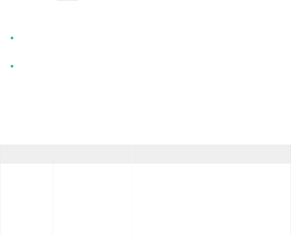
9 Creating software RAID10 devices
This section describes how to set up nested and complex RAID10 devices. A RAID10 device
consists of nested RAID 1 (mirroring) and RAID 0 (striping) arrays. Nested RAIDs can either be
set up as striped mirrors (RAID1+0) or as mirrored stripes (RAID0+1). A complex RAID10
setup also combines mirrors and stripes and additional data security by supporting a higher data
redundancy level.
9.1 Creating nested RAID 10 devices with mdadm
A nested RAID device consists of a RAID array that uses another RAID array as its basic element,
instead of using physical disks. The goal of this configuration is to improve the performance and
fault tolerance of the RAID. Setting up nested RAID levels is not supported by YaST, but can be
done by using the mdadm command line tool.
Based on the order of nesting, two different nested RAIDs can be set up. This document uses
the following terminology:
RAID 1+0: RAID 1 (mirror) arrays are built rst, then combined to form a RAID 0 (stripe)
array.
RAID 0+1: RAID 0 (stripe) arrays are built rst, then combined to form a RAID 1 (mirror)
array.
The following table describes the advantages and disadvantages of RAID 10 nesting as 1+0
versus 0+1. It assumes that the storage objects you use reside on different disks, each with a
dedicated I/O capability.
TABLE9.1:NESTED RAID LEVELS
RAID Level Description Performance and Fault Tolerance
10 (1+0) RAID 0 (stripe) built
with RAID 1 (mirror)
arrays
RAID 1+0 provides high levels of I/O perfor-
mance, data redundancy, and disk fault toler-
ance. Because each member device in the RAID
0 is mirrored individually, multiple disk failures
can be tolerated and data remains available as
long as the disks that fail are in different mirrors.
111 Creating nested RAID 10 devices with mdadm SLES 15 SP5

RAID Level Description Performance and Fault Tolerance
You can optionally configure a spare for each un-
derlying mirrored array, or configure a spare to
serve a spare group that serves all mirrors.
10 (0+1) RAID 1 (mirror) built
with RAID 0 (stripe) ar-
rays
RAID 0+1 provides high levels of I/O perfor-
mance and data redundancy, but slightly less
fault tolerance than a 1+0. If multiple disks fail
on one side of the mirror, then the other mirror
is available. However, if disks are lost concur-
rently on both sides of the mirror, all data is lost.
This solution offers less disk fault tolerance than
a 1+0 solution, but if you need to perform main-
tenance or maintain the mirror on a different
site, you can take an entire side of the mirror of-
fline and still have a fully functional storage de-
vice. Also, if you lose the connection between the
two sites, either site operates independently of
the other. That is not true if you stripe the mir-
rored segments, because the mirrors are managed
at a lower level.
If a device fails, the mirror on that side fails be-
cause RAID 1 is not fault-tolerant. Create a new
RAID 0 to replace the failed side, then resynchro-
nize the mirrors.
9.1.1 Creating nested RAID 10 (1+0) with mdadm
A nested RAID 1+0 is built by creating two or more RAID 1 (mirror) devices, then using them
as component devices in a RAID 0.
112 Creating nested RAID 10 (1+0) with mdadm SLES 15 SP5

Important: Multipathing
If you need to manage multiple connections to the devices, you must configure multipath
I/O before configuring the RAID devices. For information, see Chapter18, Managing mul-
tipath I/O for devices.
The procedure in this section uses the device names shown in the following table. Ensure that
you modify the device names with the names of your own devices.
TABLE9.2:SCENARIO FOR CREATING A RAID 10 (1+0) BY NESTING
Raw Devices RAID 1 (mirror) RAID 1+0 (striped mir-
rors)
/dev/sdb1
/dev/sdc1
/dev/md0
/dev/sdd1
/dev/sde1
/dev/md1
/dev/md2
1.
Open a terminal.
2.
If necessary, create four 0xFD Linux RAID partitions of equal size using a disk partitioner
such as parted.
3.
Create two software RAID1 devices, using two different devices for each device. At the
command prompt, enter these two commands:
> sudo mdadm --create /dev/md0 --run --level=1 --raid-devices=2 /dev/sdb1 /dev/sdc1
sudo mdadm --create /dev/md1 --run --level=1 --raid-devices=2 /dev/sdd1 /dev/sde1
4.
Create the nested RAID 1+0 device. At the command prompt, enter the following com-
mand using the software RAID 1 devices you created in the previous step:
> sudo mdadm --create /dev/md2 --run --level=0 --chunk=64 \
--raid-devices=2 /dev/md0 /dev/md1
The default chunk size is 64 KB.
5.
Create a le system on the RAID 1+0 device /dev/md2 , for example an XFS le system:
> sudo mkfs.xfs /dev/md2
113 Creating nested RAID 10 (1+0) with mdadm SLES 15 SP5

Modify the command to use a different le system.
6.
Edit the /etc/mdadm.conf le or create it, if it does not exist (for example by running
sudo vi /etc/mdadm.conf ). Add the following lines (if the le already exists, the rst
line probably already exists).
DEVICE containers partitions
ARRAY /dev/md0 UUID=UUID
ARRAY /dev/md1 UUID=UUID
ARRAY /dev/md2 UUID=UUID
The UUID of each device can be retrieved with the following command:
> sudo mdadm -D /dev/DEVICE | grep UUID
7.
Edit the /etc/fstab le to add an entry for the RAID 1+0 device /dev/md2 . The fol-
lowing example shows an entry for a RAID device with the XFS le system and /data
as a mount point.
/dev/md2 /data xfs defaults 1 2
8.
Mount the RAID device:
> sudo mount /data
9.1.2 Creating nested RAID 10 (0+1) with mdadm
A nested RAID 0+1 is built by creating two to four RAID 0 (striping) devices, then mirroring
them as component devices in a RAID 1.
Important: Multipathing
If you need to manage multiple connections to the devices, you must configure multipath
I/O before configuring the RAID devices. For information, see Chapter18, Managing mul-
tipath I/O for devices.
In this configuration, spare devices cannot be specified for the underlying RAID0 devices be-
cause RAID0 cannot tolerate a device loss. If a device fails on one side of the mirror, you must
create a replacement RAID0 device, than add it into the mirror.
114 Creating nested RAID 10 (0+1) with mdadm SLES 15 SP5

The procedure in this section uses the device names shown in the following table. Ensure that
you modify the device names with the names of your own devices.
TABLE9.3:SCENARIO FOR CREATING A RAID 10 (0+1) BY NESTING
Raw Devices RAID 0 (stripe) RAID 0+1 (mirrored
stripes)
/dev/sdb1
/dev/sdc1
/dev/md0
/dev/sdd1
/dev/sde1
/dev/md1
/dev/md2
1.
Open a terminal.
2.
If necessary, create four 0xFD Linux RAID partitions of equal size using a disk partitioner
such as parted.
3.
Create two software RAID0 devices, using two different devices for each RAID 0 device.
At the command prompt, enter these two commands:
> sudo mdadm --create /dev/md0 --run --level=0 --chunk=64 \
--raid-devices=2 /dev/sdb1 /dev/sdc1
sudo mdadm --create /dev/md1 --run --level=0 --chunk=64 \
--raid-devices=2 /dev/sdd1 /dev/sde1
The default chunk size is 64 KB.
4.
Create the nested RAID 0+1 device. At the command prompt, enter the following com-
mand using the software RAID0 devices you created in the previous step:
> sudo mdadm --create /dev/md2 --run --level=1 --raid-devices=2 /dev/md0 /dev/md1
5.
Create a le system on the RAID 1+0 device /dev/md2 , for example an XFS le system:
> sudo mkfs.xfs /dev/md2
Modify the command to use a different le system.
6.
Edit the /etc/mdadm.conf le or create it, if it does not exist (for example by running
sudo vi /etc/mdadm.conf ). Add the following lines (if the le exists, the rst line
probably already exists, too).
DEVICE containers partitions
115 Creating nested RAID 10 (0+1) with mdadm SLES 15 SP5

ARRAY /dev/md0 UUID=UUID
ARRAY /dev/md1 UUID=UUID
ARRAY /dev/md2 UUID=UUID
The UUID of each device can be retrieved with the following command:
> sudo mdadm -D /dev/DEVICE | grep UUID
7.
Edit the /etc/fstab le to add an entry for the RAID 1+0 device /dev/md2 . The fol-
lowing example shows an entry for a RAID device with the XFS le system and /data
as a mount point.
/dev/md2 /data xfs defaults 1 2
8.
Mount the RAID device:
> sudo mount /data
9.2 Creating a complex RAID 10
YaST (and mdadm with the --level=10 option) creates a single complex software RAID10
that combines features of both RAID 0 (striping) and RAID 1 (mirroring). Multiple copies of all
data blocks are arranged on multiple drives following a striping discipline. Component devices
should be the same size.
The complex RAID10 is similar in purpose to a nested RAID10 (1+0), but differs in the fol-
lowing ways:
TABLE9.4:COMPLEX RAID 10 COMPARED TO NESTED RAID 10
Feature Complex RAID10 Nested RAID10 (1+0)
Number of devices Allows an even or odd num-
ber of component devices
Requires an even number of
component devices
Component devices Managed as a single RAID
device
Manage as a nested RAID de-
vice
Striping Striping occurs in the near
or far layout on component
devices.
Striping occurs consecutively
across component devices
116 Creating a complex RAID 10 SLES 15 SP5

Feature Complex RAID10 Nested RAID10 (1+0)
The far layout provides se-
quential read throughput
that scales by number of dri-
ves, rather than number of
RAID 1 pairs.
Multiple copies of data Two or more copies, up to
the number of devices in the
array
Copies on each mirrored seg-
ment
Hot spare devices A single spare can service all
component devices
Configure a spare for each
underlying mirrored array,
or configure a spare to serve
a spare group that serves all
mirrors.
9.2.1 Number of devices and replicas in the complex RAID10
When configuring a complex RAID10 array, you must specify the number of replicas of each
data block that are required. The default number of replicas is two, but the value can be two
to the number of devices in the array.
You must use at least as many component devices as the number of replicas you specify. How-
ever, the number of component devices in a RAID10 array does not need to be a multiple of
the number of replicas of each data block. The effective storage size is the number of devices
divided by the number of replicas.
For example, if you specify two replicas for an array created with ve component devices, a
copy of each block is stored on two different devices. The effective storage size for one copy of
all data is 5/2 or 2.5 times the size of a component device.
117 Number of devices and replicas in the complex RAID10 SLES 15 SP5

9.2.2 Layout
The complex RAID10 setup supports three different layouts which define how the data blocks
are arranged on the disks. The available layouts are near (default), far and offset. They have
different performance characteristics, so it is important to choose the right layout for your work-
load.
9.2.2.1 Near layout
With the near layout, copies of a block of data are striped near each other on different component
devices. That is, multiple copies of one data block are at similar offsets in different devices. Near
is the default layout for RAID10. For example, if you use an odd number of component devices
and two copies of data, some copies are perhaps one chunk further into the device.
The near layout for the complex RAID10 yields read and write performance similar to RAID0
over half the number of drives.
Near layout with an even number of disks and two replicas:
sda1 sdb1 sdc1 sde1
0 0 1 1
2 2 3 3
4 4 5 5
6 6 7 7
8 8 9 9
Near layout with an odd number of disks and two replicas:
sda1 sdb1 sdc1 sde1 sdf1
0 0 1 1 2
2 3 3 4 4
5 5 6 6 7
7 8 8 9 9
10 10 11 11 12
9.2.2.2 Far layout
The far layout stripes data over the early part of all drives, then stripes a second copy of the data
over the later part of all drives, making sure that all copies of a block are on different drives.
The second set of values starts halfway through the component drives.
118 Layout SLES 15 SP5

With a far layout, the read performance of the complex RAID10 is similar to a RAID0 over
the full number of drives, but write performance is substantially slower than a RAID0 because
there is more seeking of the drive heads. It is best used for read-intensive operations such as
for read-only le servers.
The speed of the RAID10 for writing is similar to other mirrored RAID types, like RAID1 and
RAID10 using near layout, as the elevator of the le system schedules the writes in a more
optimal way than raw writing. Using RAID10 in the far layout is well suited for mirrored writing
applications.
Far layout with an even number of disks and two replicas:
sda1 sdb1 sdc1 sde1
0 1 2 3
4 5 6 7
. . .
3 0 1 2
7 4 5 6
Far layout with an odd number of disks and two replicas:
sda1 sdb1 sdc1 sde1 sdf1
0 1 2 3 4
5 6 7 8 9
. . .
4 0 1 2 3
9 5 6 7 8
9.2.2.3 Offset layout
The offset layout duplicates stripes so that the multiple copies of a given chunk are laid out
on consecutive drives and at consecutive offsets. Effectively, each stripe is duplicated and the
copies are offset by one device. This should give similar read characteristics to a far layout if a
suitably large chunk size is used, but without as much seeking for writes.
Offset layout with an even number of disks and two replicas:
sda1 sdb1 sdc1 sde1
0 1 2 3
3 0 1 2
4 5 6 7
7 4 5 6
8 9 10 11
119 Layout SLES 15 SP5

11 8 9 10
Offset layout with an odd number of disks and two replicas:
sda1 sdb1 sdc1 sde1 sdf1
0 1 2 3 4
4 0 1 2 3
5 6 7 8 9
9 5 6 7 8
10 11 12 13 14
14 10 11 12 13
9.2.2.4 Specifying the number of replicas and the layout with YaST and
mdadm
The number of replicas and the layout is specified as Parity Algorithm in YaST or with the --
layout parameter for mdadm. The following values are accepted:
nN
Specify n for near layout and replace N with the number of replicas. n2 is the default
that is used when not configuring layout and the number of replicas.
fN
Specify f for far layout and replace N with the number of replicas.
oN
Specify o for offset layout and replace N with the number of replicas.
Note: Number of replicas
YaST automatically offers a selection of all possible values for the Parity Algorithm para-
meter.
9.2.3 Creating a complex RAID10 with the YaST partitioner
1.
Launch YaST and open the Partitioner.
120 Creating a complex RAID10 with the YaST partitioner SLES 15 SP5

2.
If necessary, create partitions that should be used with your RAID configuration. Do not
format them and set the partition type to 0xFD Linux RAID. When using existing partitions
it is not necessary to change their partition type—YaST will automatically do so. Refer
to Book “Deployment Guide”, Chapter10 “Expert Partitioner”, Section10.1 “Using the Expert Parti-
tioner” for details.
For RAID10 at least four partitions are needed. It is strongly recommended to use parti-
tions stored on different hard disks to decrease the risk of losing data if one is defective.
It is recommended to use only partitions of the same size because each segment can con-
tribute only the same amount of space as the smallest sized partition.
3.
In the left panel, select RAID.
A list of existing RAID configurations opens in the right panel.
4.
At the lower left of the RAID page, click Add RAID.
5.
Under RAID Type, select RAID 10 (Mirroring and Striping).
You can optionally assign a RAID Name to your RAID. It will make it available as /dev/
md/NAME . See Section7.2.1, “RAID names” for more information.
6.
In the Available Devices list, select the desired partitions, then click Add to move them to
the Selected Devices list.
7.
(Optional) Click Classify to specify the preferred order of the disks in the RAID array.
121 Creating a complex RAID10 with the YaST partitioner SLES 15 SP5

For RAID types such as RAID10, where the order of added disks matters, you can specify
the order in which the devices will be used. This will ensure that one half of the array
resides on one disk subsystem and the other half of the array resides on a different disk
subsystem. For example, if one disk subsystem fails, the system keeps running from the
second disk subsystem.
a.
Select each disk in turn and click one of the Class X buttons, where X is the letter
you want to assign to the disk. Available classes are A, B, C, D and E but for many
cases fewer classes are needed (only A and B, for example). Assign all available RAID
disks this way.
You can press the
Ctrl
or
Shift
key to select multiple devices. You can also right-
click a selected device and choose the appropriate class from the context menu.
b.
Specify the order of the devices by selecting one of the sorting options:
Sorted: Sorts all devices of class A before all devices of class B and so on. For example:
AABBCC .
Interleaved: Sorts devices by the rst device of class A, then rst device of class B,
then all the following classes with assigned devices. Then the second device of class
A, the second device of class B, and so on follows. All devices without a class are
sorted to the end of the devices list. For example: ABCABC .
Pattern file: Select an existing le that contains multiple lines, where each is a reg-
ular expression and a class name ( "sda.* A" ). All devices that match the regu-
lar expression are assigned to the specified class for that line. The regular expres-
sion is matched against the kernel name ( /dev/sda1 ), the udev path name ( /dev/
disk/by-path/pci-0000:00:1f.2-scsi-0:0:0:0-part1 ) and then the udev ID
( dev/disk/by-id/ata-ST3500418AS_9VMN8X8L-part1 ). The rst match made de-
termines the class if a device’s name matches more than one regular expression.
c.
At the bottom of the dialog, click OK to confirm the order.
122 Creating a complex RAID10 with the YaST partitioner SLES 15 SP5

8.
Click Next.
9.
Under RAID Options, specify the Chunk Size and Parity Algorithm, then click Next.
For a RAID 10, the parity options are n (near), f (far), and o (offset). The number indicates
the number of replicas of each data block that are required. Two is the default. For infor-
mation, see Section9.2.2, “Layout”.
10.
Add a le system and mount options to the RAID device, then click Finish.
11.
Click Next.
12.
Verify the changes to be made, then click Finish to create the RAID.
9.2.4 Creating a complex RAID 10 with mdadm
The procedure in this section uses the device names shown in the following table. Ensure that
you modify the device names with the names of your own devices.
TABLE9.5:SCENARIO FOR CREATING A RAID10 USING MDADM
Raw Devices RAID10
/dev/sdf1 /dev/md3
123 Creating a complex RAID 10 with mdadm SLES 15 SP5

Raw Devices RAID10
/dev/sdg1
/dev/sdh1
/dev/sdi1
1.
Open a terminal.
2.
If necessary, create at least four 0xFD Linux RAID partitions of equal size using a disk
partitioner such as parted.
3.
Create a RAID10 by entering the following command.
> sudo mdadm --create /dev/md3 --run --level=10 --chunk=32 --raid-devices=4 \
/dev/sdf1 /dev/sdg1 /dev/sdh1 /dev/sdi1
Make sure to adjust the value for --raid-devices and the list of partitions according
to your setup.
The command creates an array with near layout and two replicas. To change any of the two
values, use the --layout as described in Section9.2.2.4, “Specifying the number of replicas
and the layout with YaST and mdadm”.
4.
Create a le system on the RAID10 device /dev/md3 , for example an XFS le system:
> sudo mkfs.xfs /dev/md3
Modify the command to use a different le system.
5.
Edit the /etc/mdadm.conf le or create it, if it does not exist (for example by running
sudo vi /etc/mdadm.conf ). Add the following lines (if the le exists, the rst line
probably already exists, too).
DEVICE containers partitions
ARRAY /dev/md3 UUID=UUID
The UUID of the device can be retrieved with the following command:
> sudo mdadm -D /dev/md3 | grep UUID
6.
Edit the /etc/fstab le to add an entry for the RAID10 device /dev/md3 . The following
example shows an entry for a RAID device with the XFS le system and /data as a mount
point.
124 Creating a complex RAID 10 with mdadm SLES 15 SP5

/dev/md3 /data xfs defaults 1 2
7.
Mount the RAID device:
> sudo mount /data
125 Creating a complex RAID 10 with mdadm SLES 15 SP5

10 Creating a degraded RAID array
A degraded array is one in which some devices are missing. Degraded arrays are
supported only for RAID 1, RAID 4, RAID 5, and RAID 6. These RAID types are de-
signed to withstand some missing devices as part of their fault-tolerance features.
Typically, degraded arrays occur when a device fails. It is possible to create a de-
graded array on purpose.
RAID Type Allowable Number of Slots Missing
RAID 1 All but one device
RAID 4 One slot
RAID 5 One slot
RAID 6 One or two slots
To create a degraded array in which some devices are missing, simply give the word missing
in place of a device name. This causes mdadm to leave the corresponding slot in the array empty.
When creating a RAID 5 array, mdadm automatically creates a degraded array with an extra
spare drive. This is because building the spare into a degraded array is generally faster than
resynchronizing the parity on a non-degraded, but not clean, array. You can override this feature
with the --force option.
Creating a degraded array might be useful if you want create a RAID, but one of the devices you
want to use already has data on it. In that case, you create a degraded array with other devices,
copy data from the in-use device to the RAID that is running in degraded mode, add the device
into the RAID, then wait while the RAID is rebuilt so that the data is now across all devices. An
example of this process is given in the following procedure:
1.
To create a degraded RAID 1 device /dev/md0 , using one single drive /dev/sd1 , enter
the following at the command prompt:
> sudo mdadm --create /dev/md0 -l 1 -n 2 /dev/sda1 missing
The device should be the same size or larger than the device you plan to add to it.
126 SLES 15 SP5

2.
If the device you want to add to the mirror contains data that you want to move to the
RAID array, copy it now to the RAID array while it is running in degraded mode.
3.
Add the device you copied the data from to the mirror. For example, to add /dev/sdb1
to the RAID, enter the following at the command prompt:
> sudo mdadm /dev/md0 -a /dev/sdb1
You can add only one device at a time. You must wait for the kernel to build the mirror
and bring it fully online before you add another mirror.
4.
Monitor the build progress by entering the following at the command prompt:
> sudo cat /proc/mdstat
To see the rebuild progress while being refreshed every second, enter
> sudo watch -n 1 cat /proc/mdstat
127 SLES 15 SP5

11 Resizing software RAID arrays with mdadm
This section describes how to increase or reduce the size of a software RAID 1, 4, 5,
or 6 device with the Multiple Device Administration ( mdadm(8) ) tool.
Resizing an existing software RAID device involves increasing or decreasing the space con-
tributed by each component partition. The le system that resides on the RAID must also be able
to be resized to take advantage of the changes in available space on the device. In SUSE Linux
Enterprise Server, le system resizing utilities are available for le systems Btrfs, Ext2, Ext3,
Ext4, and XFS (increase size only). Refer to Chapter2, Resizing file systems for more information.
The mdadm tool supports resizing only for software RAID levels 1, 4, 5, and 6. These RAID
levels provide disk fault tolerance so that one component partition can be removed at a time
for resizing. In principle, it is possible to perform a hot resize for RAID partitions, but you must
take extra care for your data when doing so.
Warning: Back up your data before resizing
Resizing any partition or le system involves some risks that can potentially result in
losing data. To avoid data loss, ensure that you back up your data before you begin any
resizing task.
Resizing the RAID involves the following tasks. The order in which these tasks are performed
depends on whether you are increasing or decreasing its size.
TABLE11.1:TASKS INVOLVED IN RESIZING A RAID
Tasks Description Order If
Increas-
ing Size
Order If
Decreas-
ing Size
Resize each of the
component parti-
tions.
Increase or decrease the active size of each
component partition. You remove only one
component partition at a time, modify its
size, then return it to the RAID.
1 2
128 SLES 15 SP5

Tasks Description Order If
Increas-
ing Size
Order If
Decreas-
ing Size
Resize the software
RAID itself.
The RAID does not automatically know
about the increases or decreases you make
to the underlying component partitions. You
must inform it about the new size.
2 3
Resize the le sys-
tem.
You must resize the le system that resides
on the RAID. This is possible only for le
systems that provide tools for resizing.
3 1
The procedures in the following sections use the device names shown in the following table.
Ensure that you modify the names to use the names of your own devices.
TABLE11.2:SCENARIO FOR INCREASING THE SIZE OF COMPONENT PARTITIONS
RAID Device Component Partitions
/dev/md0 /dev/sda1
/dev/sdb1
/dev/sdc1
11.1 Increasing the size of a software RAID
Increasing the size of a software RAID involves the following tasks in the given order: increase
the size of all partitions the RAID consists of, increase the size of the RAID itself and, finally,
increase the size of the le system.
Warning: Potential data loss
If a RAID does not have disk fault tolerance, or it is simply not consistent, data loss results
if you remove any of its partitions. Be very careful when removing partitions, and ensure
that you have a backup of your data available.
129 Increasing the size of a software RAID SLES 15 SP5

11.1.1 Increasing the size of component partitions
Apply the procedure in this section to increase the size of a RAID 1, 4, 5, or 6. For each compo-
nent partition in the RAID, remove the partition from the RAID, modify its size, return it to the
RAID, then wait until the RAID stabilizes to continue. While a partition is removed, the RAID
operates in degraded mode and has no or reduced disk fault tolerance. Even for RAIDs that can
tolerate multiple concurrent disk failures, do not remove more than one component partition at
a time. To increase the size of the component partitions for the RAID, proceed as follows:
1.
Open a terminal.
2.
Ensure that the RAID array is consistent and synchronized by entering
> cat /proc/mdstat
If your RAID array is still synchronizing according to the output of this command, you
must wait until synchronization is complete before continuing.
3.
Remove one of the component partitions from the RAID array. For example, to remove
/dev/sda1 , enter
> sudo mdadm /dev/md0 --fail /dev/sda1 --remove /dev/sda1
To succeed, both the fail and remove actions must be specified.
4.
Increase the size of the partition that you removed in the previous step by doing one of
the following:
Increase the size of the partition, using a disk partitioner such as the YaST Partitioner
or the command line tool parted. This option is the usual choice.
Replace the disk on which the partition resides with a higher-capacity device. This
option is possible only if no other le systems on the original disk are accessed by
the system. When the replacement device is added back into the RAID, it takes much
longer to synchronize the data because all of the data that was on the original device
must be rebuilt.
5.
Re-add the partition to the RAID array. For example, to add /dev/sda1 , enter
> sudo mdadm -a /dev/md0 /dev/sda1
Wait until the RAID is synchronized and consistent before continuing with the next par-
tition.
130 Increasing the size of component partitions SLES 15 SP5

6.
Repeat these steps for each of the remaining component devices in the array. Ensure that
you modify the commands for the correct component partition.
7.
If you get a message that tells you that the kernel could not re-read the partition table
for the RAID, you must reboot the computer after all partitions have been resized to force
an update of the partition table.
8.
Continue with Section11.1.2, “Increasing the size of the RAID array”.
11.1.2 Increasing the size of the RAID array
After you have resized each of the component partitions in the RAID (see Section11.1.1, “Increasing
the size of component partitions”), the RAID array configuration continues to use the original array
size until you force it to be aware of the newly available space. You can specify a size for the
RAID or use the maximum available space.
The procedure in this section uses the device name /dev/md0 for the RAID device. Ensure that
you modify the name to use the name of your own device.
1.
Open a terminal.
2.
Ensure that the RAID array is consistent and synchronized by entering
> cat /proc/mdstat
If your RAID array is still synchronizing according to the output of this command, you
must wait until synchronization is complete before continuing.
3.
Check the size of the array and the device size known to the array by entering
> sudo mdadm -D /dev/md0 | grep -e "Array Size" -e "Dev Size"
4.
Do one of the following:
Increase the size of the array to the maximum available size by entering
> sudo mdadm --grow /dev/md0 -z max
Increase the size of the array to the maximum available size by entering
> sudo mdadm --grow /dev/md0 -z max --assume-clean
131 Increasing the size of the RAID array SLES 15 SP5

The array uses any space that has been added to the devices, but this space will not
be synchronized. This is recommended for RAID1 because the synchronization is
not needed. It can be useful for other RAID levels if the space that was added to the
member devices was pre-zeroed.
Increase the size of the array to a specified value by entering
> sudo mdadm --grow /dev/md0 -z SIZE
Replace SIZE with an integer value in kilobytes (a kilobyte is 1024 bytes) for the
desired size.
5.
Recheck the size of your array and the device size known to the array by entering
> sudo mdadm -D /dev/md0 | grep -e "Array Size" -e "Dev Size"
6.
Do one of the following:
If your array was successfully resized, continue with Section11.1.3, “Increasing the size
of the file system”.
If your array was not resized as you expected, you must reboot, then try this proce-
dure again.
11.1.3 Increasing the size of the file system
After you increase the size of the array (see Section11.1.2, “Increasing the size of the RAID array”),
you are ready to resize the le system.
You can increase the size of the le system to the maximum space available or specify an exact
size. When specifying an exact size for the le system, ensure that the new size satisfies the
following conditions:
The new size must be greater than the size of the existing data; otherwise, data loss occurs.
The new size must be equal to or less than the current RAID size because the le system
size cannot extend beyond the space available.
Refer to Chapter2, Resizing file systems for detailed instructions.
132 Increasing the size of the file system SLES 15 SP5

11.2 Decreasing the size of a software RAID
Decreasing the Size of a Software RAID involves the following tasks in the given order: decrease
the size of the le system, decrease the size of all partitions the RAID consists of, and finally
decrease the size of the RAID itself.
Warning: Potential data loss
If a RAID does not have disk fault tolerance, or it is simply not consistent, data loss results
if you remove any of its partitions. Be very careful when removing partitions, and ensure
that you have a backup of your data available.
Important: XFS
Decreasing the size of a le system formatted with XFS is not possible, since such a feature
is not supported by XFS. As a consequence, the size of a RAID that uses the XFS le system
cannot be decreased.
11.2.1 Decreasing the size of the file system
When decreasing the size of the le system on a RAID device, ensure that the new size satisfies
the following conditions:
The new size must be greater than the size of the existing data; otherwise, data loss occurs.
The new size must be equal to or less than the current RAID size because the le system
size cannot extend beyond the space available.
Refer to Chapter2, Resizing file systems for detailed instructions.
11.2.2 Decreasing the size of the RAID array
After you have resized the le system (see Section11.2.1, “Decreasing the size of the file system”),
the RAID array configuration continues to use the original array size until you force it to reduce
the available space. Use the mdadm --grow mode to force the RAID to use a smaller segment
133 Decreasing the size of a software RAID SLES 15 SP5

size. To do this, you must use the -z option to specify the amount of space in kilobytes to use
from each device in the RAID. This size must be a multiple of the chunk size, and it must leave
about 128 KB of space for the RAID superblock to be written to the device.
The procedure in this section uses the device name /dev/md0 for the RAID device. Ensure that
you modify commands to use the name of your own device.
1.
Open a terminal.
2.
Check the size of the array and the device size known to the array by entering
> sudo mdadm -D /dev/md0 | grep -e "Array Size" -e "Dev Size"
3.
Decrease the array’s device size to a specified value by entering
> sudo mdadm --grow /dev/md0 -z SIZE
Replace SIZE with an integer value in kilobytes for the desired size. (A kilobyte is 1024
bytes.)
For example, the following command sets the segment size for each RAID device to about
40 GB where the chunk size is 64 KB. It includes 128 KB for the RAID superblock.
> sudo mdadm --grow /dev/md2 -z 41943168
4.
Recheck the size of your array and the device size known to the array by entering
> sudo mdadm -D /dev/md0 | grep -e "Array Size" -e "Device Size"
5.
Do one of the following:
If your array was successfully resized, continue with Section11.2.3, “Decreasing the size
of component partitions”.
If your array was not resized as you expected, you must reboot, then try this proce-
dure again.
11.2.3 Decreasing the size of component partitions
After you decrease the segment size that is used on each device in the RAID (see Section11.2.2,
“Decreasing the size of the RAID array”), the remaining space in each component partition is not
used by the RAID. You can leave partitions at their current size to allow for the RAID to grow
at a future time, or you can reclaim this now unused space.
134 Decreasing the size of component partitions SLES 15 SP5

To reclaim the space, you decrease the component partitions one at a time. For each component
partition, you remove it from the RAID, reduce its partition size, return the partition to the RAID,
then wait until the RAID stabilizes. To allow for metadata, you should specify a slightly larger
size than the size you specified for the RAID in Section11.2.2, “Decreasing the size of the RAID array”.
While a partition is removed, the RAID operates in degraded mode and has no or reduced disk
fault tolerance. Even for RAIDs that can tolerate multiple concurrent disk failures, you should
never remove more than one component partition at a time. To decrease the size of the compo-
nent partitions for the RAID, proceed as follows:
1.
Open a terminal.
2.
Ensure that the RAID array is consistent and synchronized by entering
> cat /proc/mdstat
If your RAID array is still synchronizing according to the output of this command, you
must wait until synchronization is complete before continuing.
3.
Remove one of the component partitions from the RAID array. For example, to remove
/dev/sda1 , enter
> sudo mdadm /dev/md0 --fail /dev/sda1 --remove /dev/sda1
To succeed, both the fail and remove actions must be specified.
4.
Decrease the size of the partition that you removed in the previous step to a size that is
slightly larger than the size you set for the segment size. The size should be a multiple of
the chunk size and allow 128 KB for the RAID superblock. Use a disk partitioner such as
the YaST partitioner or the command line tool parted to decrease the size of the partition.
5.
Re-add the partition to the RAID array. For example, to add /dev/sda1 , enter
> sudo mdadm -a /dev/md0 /dev/sda1
Wait until the RAID is synchronized and consistent before continuing with the next par-
tition.
6.
Repeat these steps for each of the remaining component devices in the array. Ensure that
you modify the commands for the correct component partition.
7.
If you get a message that tells you that the kernel could not re-read the partition table for
the RAID, you must reboot the computer after resizing all of its component partitions.
135 Decreasing the size of component partitions SLES 15 SP5

8.
(Optional) Expand the size of the RAID and le system to use the maximum amount of
space in the now smaller component partitions and increase the size of the le system
afterward. Refer to Section11.1.2, “Increasing the size of the RAID array” for instructions.
136 Decreasing the size of component partitions SLES 15 SP5

12 Storage enclosure LED utilities for MD software
RAIDs
Storage enclosure LED Monitoring utility ( ledmon ) and LED Control ( ledctl ) util-
ity are Linux user space applications that use a broad range of interfaces and pro-
tocols to control storage enclosure LEDs. The primary usage is to visualize the sta-
tus of Linux MD software RAID devices created with the mdadm utility. The led-
mon daemon monitors the status of the drive array and updates the status of the dri-
ve LEDs. The ledctl utility allows you to set LED patterns for specified devices.
These LED utilities use the SGPIO (Serial General Purpose Input/Output) specification (Small
Form Factor (SFF) 8485) and the SCSI Enclosure Services (SES) 2 protocol to control LEDs. They
implement the International Blinking Pattern Interpretation (IBPI) patterns of the SFF-8489
specification for SGPIO. The IBPI defines how the SGPIO standards are interpreted as states for
drives and slots on a backplane and how the backplane should visualize the states with LEDs.
Some storage enclosures do not adhere strictly to the SFF-8489 specification. An enclosure
processor might accept an IBPI pattern but not blink the LEDs according to the SFF-8489 spec-
ification, or the processor might support only a limited number of the IBPI patterns.
LED management (AHCI) and SAF-TE protocols are not supported by the ledmon and ledctl
utilities.
The ledmon and ledctl applications have been verified to work with Intel storage controllers
such as the Intel AHCI controller and Intel SAS controller. They also support PCIe-SSD (sol-
id-state drive) enclosure LEDs to control the storage enclosure status (OK, Fail, Rebuilding) LEDs
of PCIe-SSD devices that are part of an MD software RAID volume. The applications might al-
so work with the IBPI-compliant storage controllers of other vendors (especially SAS/SCSI con-
trollers); however, other vendors’ controllers have not been tested.
ledmon and ledctl are part of the ledmon package, which is not installed by default. Run
sudo zypper in ledmon to install it.
137 SLES 15 SP5

12.1 The storage enclosure LED monitor service
The ledmon application is a daemon process that constantly monitors the state of MD software
RAID devices or the state of block devices in a storage enclosure or drive bay. Only a single
instance of the daemon should be running at a time. The ledmon daemon is part of Intel En-
closure LED Utilities.
The state is visualized on LEDs associated with each slot in a storage array enclosure or a drive
bay. The application monitors all software RAID devices and visualizes their state. It does not
provide a way to monitor only selected software RAID volumes.
The ledmon daemon supports two types of LED systems: A two-LED system (Activity LED and
Status LED) and a three-LED system (Activity LED, Locate LED, and Fail LED). This tool has the
highest priority when accessing the LEDs.
To start ledmon , enter
> sudo ledmon [options]
where [options] is one or more of the following:
OPTIONS FOR ledmon
-c PATH ,
--confg=PATH
The configuration is read from ~/.ledctl or from /etc/ledcfg.conf if existing. Use
this option to specify an alternative configuration le.
Currently this option has no effect, since support for configuration les has not been im-
plemented yet. See man 5 ledctl.conf for details.
-l PATH ,
--log= PATH
Sets a path to local log le. If this user-defined le is specified, the global log le /var/
log/ledmon.log is not used.
-t SECONDS ,
--interval=SECONDS
Sets the time interval between scans of sysfs . The value is given in seconds. The minimum
is 5 seconds. The maximum is not specified.
138 The storage enclosure LED monitor service SLES 15 SP5

--quiet , --error , --warning , --info , --debug , --all
Specifies the verbosity level. The level options are specified in the order of no information
to the most information. Use the --quiet option for no logging. Use the --all option
to log everything. If you specify more than one verbose option, the last option in the
command applies.
-h ,
--help
Prints the command information to the console, then exits.
-v ,
--version
Displays version of ledmon and information about the license, then exits.
Note: Known issues
The ledmon daemon does not recognize the PFA (Predicted Failure Analysis) state from
the SFF-8489 specification. Thus, the PFA pattern is not visualized.
12.2 The storage enclosure LED control application
The Enclosure LED Application ( ledctl ) is a user space application that controls LEDs associ-
ated with each slot in a storage enclosure or a drive bay. The ledctl application is a part of
Intel Enclosure LED Utilities.
When you issue the command, the LEDs of the specified devices are set to a specified pattern and
all other LEDs are turned o. This application needs to be run with root privileges. Because the
ledmon application has the highest priority when accessing LEDs, some patterns set by ledctl
might have no effect if the ledmon daemon is running (except for the Locate pattern).
The ledctl application supports two types of LED systems: A two-LED system (Activity LED
and Status LED) and a three-LED system (Activity LED, Fail LED, and Locate LED).
To start ledctl , enter
> sudo [options] PATTERN_NAME=list_of_devices
139 The storage enclosure LED control application SLES 15 SP5

where [options] is one or more of the following:
-c PATH ,
--confg=PATH
Sets a path to local configuration le. If this option is specified, the global configuration
le and user configuration le have no effect.
-l PATH ,
--log= PATH
Sets a path to local log le. If this user-defined le is specified, the global log le /var/
log/ledmon.log is not used.
--quiet
Turns o all messages sent to stdout or stderr out. The messages are still logged to
local le and the syslog facility.
-h ,
--help
Prints the command information to the console, then exits.
-v ,
--version
Displays version of ledctl and information about the license, then exits.
12.2.1 Pattern names
The ledctl application accepts the following names for pattern_name argument, according to
the SFF-8489 specification.
locate
Turns on the Locate LED associated with the specified devices or empty slots. This state
is used to identify a slot or drive.
locate_off
Turns o the Locate LED associated with the specified devices or empty slots.
normal
Turns o the Status LED, Failure LED, and Locate LED associated with the specified devices.
off
Turns o only the Status LED and Failure LED associated with the specified devices.
140 Pattern names SLES 15 SP5

ica ,
degraded
Visualizes the In a Critical Array pattern.
rebuild ,
rebuild_p
Visualizes the Rebuild pattern. This supports both of the rebuild states for compatibility
and legacy reasons.
ifa ,
failed_array
Visualizes the In a Failed Array pattern.
hotspare
Visualizes the Hotspare pattern.
pfa
Visualizes the Predicted Failure Analysis pattern.
failure ,
disk_failed
Visualizes the Failure pattern.
ses_abort
SES-2 R/R ABORT
ses_rebuild
SES-2 REBUILD/REMAP
ses_ifa
SES-2 IN FAILED ARRAY
ses_ica
SES-2 IN CRITICAL ARRAY
ses_cons_check
SES-2 CONS CHECK
ses_hotspare
SES-2 HOTSPARE
ses_rsvd_dev
SES-2 RSVD DEVICE
141 Pattern names SLES 15 SP5

ses_ok
SES-2 OK
ses_ident
SES-2 IDENT
ses_rm
SES-2 REMOVE
ses_insert
SES-2 INSERT
ses_missing
SES-2 MISSING
ses_dnr
SES-2 DO NOT REMOVE
ses_active
SES-2 ACTIVE
ses_enable_bb
SES-2 ENABLE BYP B
ses_enable_ba
SES-2 ENABLE BYP A
ses_devoff
SES-2 DEVICE OFF
ses_fault
SES-2 FAULT
When a non-SES-2 pattern is sent to a device in an enclosure, the pattern is automatically trans-
lated to the SCSI Enclosure Services (SES) 2 pattern as shown above.
TABLE12.1:TRANSLATION BETWEEN NON-SES-2 PATTERNS AND SES-2 PATTERNS
Non-SES-2 Pattern SES-2 Pattern
locate ses_ident
locate_off ses_ident
normal ses_ok
142 Pattern names SLES 15 SP5

Non-SES-2 Pattern SES-2 Pattern
o ses_ok
ica ses_ica
degraded ses_ica
rebuild ses_rebuild
rebuild_p ses_rebuild
ifa ses_ifa
failed_array ses_ifa
hotspare ses_hotspare
pfa ses_rsvd_dev
failure ses_fault
disk_failed ses_fault
12.2.2 List of devices
When you issue the ledctl command, the LEDs of the specified devices are set to the specified
pattern and all other LEDs are turned o. The list of devices can be provided in one of two
formats:
A list of devices separated by a comma and no spaces
A list in curly braces with devices separated by a space
If you specify multiple patterns in the same command, the device list for each pattern can use
the same or different format. For examples that show the two list formats, see Section12.2.3,
“Examples”.
A device is a path to le in the /dev directory or in the /sys/block directory. The path can
identify a block device, an MD software RAID device, or a container device. For a software RAID
device or a container device, the reported LED state is set for all of the associated block devices.
143 List of devices SLES 15 SP5

The LEDs of devices listed in list_of_devices are set to the given pattern pattern_name and all
other LEDs are turned o.
12.2.3 Examples
To locate a single block device:
> sudo ledctl locate=/dev/sda
To turn o the Locate LED for a single block device:
> sudo ledctl locate_off=/dev/sda
To locate disks of an MD software RAID device and to set a rebuild pattern for two of its block
devices at the same time:
> sudo ledctl locate=/dev/md127 rebuild={ /sys/block/sd[a-b] }
To turn o the Status LED and Failure LED for the specified devices:
> sudo ledctl off={ /dev/sda /dev/sdb }
To locate three block devices, run one of the following commands (both are equivalent):
> sudo ledctl locate=/dev/sda,/dev/sdb,/dev/sdc
> sudo ledctl locate={ /dev/sda /dev/sdb /dev/sdc }
12.3 More information
See the following resources for details about the LED patterns and monitoring tools:
LEDMON open source project on GitHub.com (https://github.com/intel/ledmon.git)
144 Examples SLES 15 SP5

13 Troubleshooting software RAIDs
Check the /proc/mdstat le to nd out whether a RAID partition has been damaged. If a disk
fails, replace the defective hard disk with a new one partitioned the same way. Then restart
your system and enter the command mdadm /dev/mdX --add /dev/sdX . Replace X with your
particular device identifiers. This integrates the hard disk automatically into the RAID system
and fully reconstructs it (for all RAID levels except for RAID0).
Although you can access all data during the rebuild, you might encounter some performance
issues until the RAID has been fully rebuilt.
13.1 Recovery after failing disk is back again
There are several reasons a disk included in a RAID array may fail. Here is a list of the most
common ones:
Problems with the disk media.
Disk drive controller failure.
Broken connection to the disk.
In the case of disk media or controller failure, the device needs to be replaced or repaired. If a
hot spare was not configured within the RAID, then manual intervention is required.
In the last case, the failed device can be automatically re-added with the mdadm command after
the connection is repaired (which might be automatic).
Because md / mdadm cannot reliably determine what caused the disk failure, it assumes a serious
disk error and treats any failed device as faulty until it is explicitly told that the device is reliable.
Under some circumstances—such as storage devices with an internal RAID array—connection
problems are very often the cause of the device failure. In such case, you can tell mdadm that
it is safe to automatically --re-add the device after it appears. You can do this by adding the
following line to /etc/mdadm.conf :
POLICY action=re-add
Note that the device will be automatically re-added after re-appearing only if the udev rules
cause mdadm -I DISK_DEVICE_NAME to be run on any device that spontaneously appears (de-
fault behavior), and if write-intent bitmaps are configured (they are by default).
145 Recovery after failing disk is back again SLES 15 SP5

If you want this policy to only apply to some devices and not to the others, then the path= option
can be added to the POLICY line in /etc/mdadm.conf to restrict the non-default action to only
selected devices. Wild cards can be used to identify groups of devices. See man 5 mdadm.conf
for more information.
146 Recovery after failing disk is back again SLES 15 SP5

14 iSNS for Linux
Storage area networks (SANs) can contain many disk drives that are dispersed across complex
networks. This can make device discovery and device ownership difficult. iSCSI initiators must
be able to identify storage resources in the SAN and determine whether they have access to them.
Internet Storage Name Service (iSNS) is a standards-based service that simplifies the automat-
ed discovery, management, and configuration of iSCSI devices on a TCP/IP network. iSNS pro-
vides intelligent storage discovery and management services comparable to those found in Fibre
Channel networks.
Without iSNS, you must know the host name or IP address of each node where targets of interest
are located. In addition, you must manually manage which initiators can access which targets
yourself using mechanisms such as access control lists.
Important: Security considerations
iSNS should only be used in secure internal networking environments, as the network
traffic is not encrypted.
14.1 How iSNS works
For an iSCSI initiator to discover iSCSI targets, it needs to identify which devices in the network
are storage resources and what IP addresses it needs to access them. A query to an iSNS server
returns a list of iSCSI targets and the IP addresses that the initiator has permission to access.
Using iSNS, you create iSNS discovery domains into which you then group or organize iSCSI tar-
gets and initiators. By dividing storage nodes into domains, you can limit the discovery process
of each host to the most appropriate subset of targets registered with iSNS, which allows the
storage network to scale by reducing the number of unnecessary discoveries and by limiting the
amount of time each host spends establishing discovery relationships. This lets you control and
simplify the number of targets and initiators that must be discovered.
148 How iSNS works SLES 15 SP5

FIGURE14.1:ISNS DISCOVERY DOMAINS
Both iSCSI targets and iSCSI initiators can use iSNS clients to initiate transactions with iSNS
servers by using the iSNS protocol. They then register device attribute information in a common
discovery domain, download information about other registered clients, and receive asynchro-
nous notification of events that occur in their discovery domain.
iSNS servers respond to iSNS protocol queries and requests made by iSNS clients using the
iSNS protocol. iSNS servers initiate iSNS protocol state change notifications and store properly
authenticated information submitted by a registration request in an iSNS database.
Benefits provided by iSNS for Linux include:
Provides an information facility for registration, discovery, and management of networked
storage assets.
Integrates with the DNS infrastructure.
Consolidates registration, discovery, and management of iSCSI storage.
Simplifies storage management implementations.
Improves scalability compared to other discovery methods.
iSNS offers several important benefits.
For example, in a setup with 100 iSCSI initiators and 100 iSCSI targets, all iSCSI initiators could
potentially try to discover and connect to any of the 100 iSCSI targets. By grouping initiators
and targets into discovery domains, you can prevent iSCSI initiators in one department from
discovering the iSCSI targets in another department.
149 How iSNS works SLES 15 SP5

Another advantage of using iSNS is that the iSCSI clients only need to know the host name or
IP address of the iSNS server, rather than having to know the host names or IP addresses of a
hundred servers.
14.2 Installing iSNS server for Linux
iSNS Server for Linux is included with SUSE Linux Enterprise Server, but is not installed or con-
figured by default. You need to install the package open-isns and configure the iSNS service.
Note: iSNS and iSCSI on the same server
iSNS can be installed on the same server where iSCSI target or iSCSI initiator software
is installed. Installing both the iSCSI target software and iSCSI initiator software on the
same server is not supported.
To install iSNS for Linux:
1.
Start YaST and select Network Services iSNS Server.
2.
In case open-isns is not installed yet, you are prompted to install it now. Confirm by
clicking Install.
3.
The iSNS Service configuration dialog opens automatically to the Service tab.
150 Installing iSNS server for Linux SLES 15 SP5
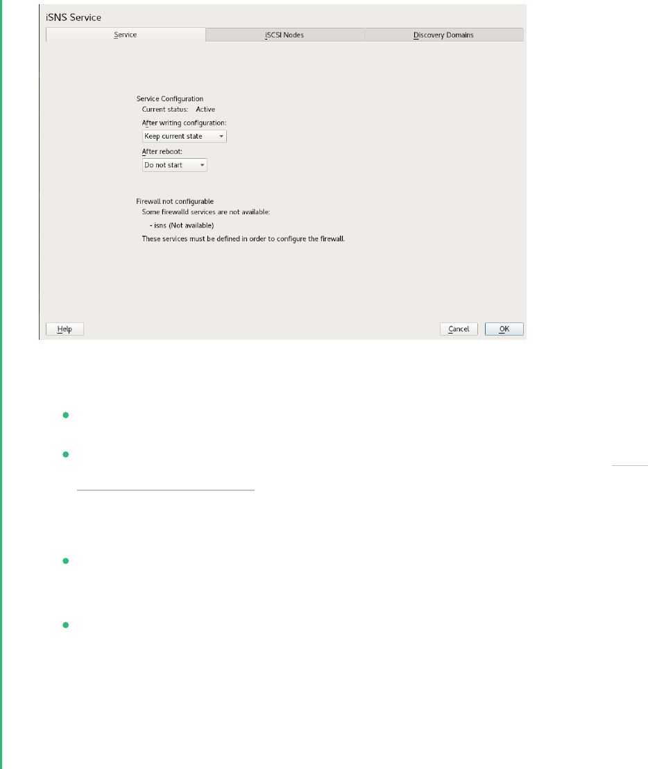
4.
In Service Start, select one of the following:
When booting: The iSNS service starts automatically on server start-up.
Manually (default): The iSNS service must be started manually by entering sudo
systemctl start isnsd at the server console of the server where you install it.
5.
Specify the following firewall settings:
Open port in firewall: Select the check box to open the firewall and allow access to
the service from remote computers. The firewall port is closed by default.
Firewall details: If you open the firewall port, the port is open on all network inter-
faces by default. Click Firewall Details to select interfaces on which to open the port,
select the network interfaces to use, then click OK.
6.
Click OK to apply the configuration settings and complete the installation.
7.
Continue with Section14.3, “Configuring iSNS discovery domains”.
14.3 Configuring iSNS discovery domains
For iSCSI initiators and targets to use the iSNS service, they must belong to a discovery domain.
151 Configuring iSNS discovery domains SLES 15 SP5

Important: The iSNS service must be active
The iSNS service must be installed and running to configure iSNS discovery domains. For
information, see Section14.4, “Starting the iSNS service”.
14.3.1 Creating iSNS discovery domains
A default discovery domain named default DD is automatically created when you install the
iSNS service. The existing iSCSI targets and initiators that have been configured to use iSNS are
automatically added to the default discovery domain.
To create a new discovery domain:
1.
Start YaST and under Network Services, select iSNS Server.
2.
Click the Discovery Domains tab.
The Discovery Domains area lists all existing discovery domains. You can Create Discovery
Domains, or Delete existing ones. Keep in mind that deleting an iSCSI node from domain
membership removes it from the domain, but it does not delete the iSCSI node.
The Discovery Domain Members area lists all iSCSI nodes assigned to a selected discovery
domain. Selecting a different discovery domain refreshes the list with members from that
discovery domain. You can add and delete iSCSI nodes from a selected discovery domain.
Deleting an iSCSI node removes it from the domain, but it does not delete the iSCSI node.
Create iSCSI Node Member allows a node that is not yet registered to be added as a member
of the discovery domain. When the iSCSI initiator or target registers this node, then it
becomes part of this domain.
When an iSCSI initiator performs a discovery request, the iSNS service returns all iSCSI
node targets that are members of the same discovery domain.
152 Creating iSNS discovery domains SLES 15 SP5

3.
Click the Create Discovery Domain button.
You can also select an existing discovery domain and click the Delete button to remove
that discovery domain.
4.
Specify the name of the discovery domain you are creating, then click OK.
5.
Continue with Section14.3.2, “Adding iSCSI nodes to a discovery domain”.
14.3.2 Adding iSCSI nodes to a discovery domain
1.
Start YaST and under Network Services, select iSNS Server.
2.
Click the iSCSI Nodes tab.
153 Adding iSCSI nodes to a discovery domain SLES 15 SP5

3.
Review the list of nodes to ensure that the iSCSI targets and initiators that you want to
use the iSNS service are listed.
If an iSCSI target or initiator is not listed, you might need to restart the iSCSI service on
the node. You can do this by running
> sudo systemctl restart iscsid.socket
> sudo systemctl restart iscsi
to restart an initiator or
> sudo systemctl restart target-isns
to restart a target.
You can select an iSCSI node and click the Delete button to remove that node from the
iSNS database. This is useful if you are no longer using an iSCSI node or have renamed it.
The iSCSI node is automatically added to the list (iSNS database) again when you restart
the iSCSI service or reboot the server unless you remove or comment out the iSNS portion
of the iSCSI configuration le.
4.
Click the Discovery Domains tab and select the desired discovery domain.
5.
Click Add existing iSCSI Node, select the node you want to add to the domain, then click
Add Node.
154 Adding iSCSI nodes to a discovery domain SLES 15 SP5

6.
Repeat the previous step for as many nodes as you want to add to the discovery domain,
then click Done when you are finished adding nodes.
Note that an iSCSI node can belong to more than one discovery domain.
14.4 Starting the iSNS service
iSNS must be started at the server where you install it. If you have not configured it to be started
at boot time (see Section14.2, “Installing iSNS server for Linux” for details), enter the following
command at a terminal:
> sudo systemctl start isnsd
You can also use the stop , status , and restart options with iSNS.
14.5 More information
The following projects provide further information on iSNS and iSCSI:
iSNS server and client for Linux project (https://github.com/open-iscsi/open-isns)
iSNS client for the Linux LIO iSCSI target (https://github.com/open-iscsi/target-isns)
iSCSI tools for Linux (https://www.open-iscsi.com)
General information about iSNS is available in RFC 4171: Internet Storage Name Service at https://
datatracker.ietf.org/doc/html/rfc4171 .
155 Starting the iSNS service SLES 15 SP5

15 Mass storage over IP networks: iSCSI
One of the primary tasks of a computer center, or any site that supports servers, is to provide
adequate disk capacity. Fibre Channel is often used for this purpose. iSCSI (Internet SCSI) so-
lutions provide a lower-cost alternative to Fibre Channel that can leverage commodity servers
and Ethernet networking equipment. Linux iSCSI provides iSCSI initiator and iSCSI LIO target
software for connecting Linux servers to central storage systems.
FIGURE15.1:ISCSI SAN WITH AN ISNS SERVER
Note: LIO
LIO is the standard open source multiprotocol SCSI target for Linux. LIO replaced the
STGT (SCSI Target) framework as the standard unified storage target in Linux with Linux
kernel version 2.6.38 and later. In SUSE Linux Enterprise Server 12 the iSCSI LIO Target
Server replaces the iSCSI Target Server from previous versions.
156 SLES 15 SP5

iSCSI is a storage networking protocol that simplifies data transfers of SCSI packets over TCP/
IP networks between block storage devices and servers. iSCSI target software runs on the target
server and defines the logical units as iSCSI target devices. iSCSI initiator software runs on
different servers and connects to the target devices to make the storage devices available on
that server.
The iSCSI LIO target server and iSCSI initiator servers communicate by sending SCSI packets at
the IP level in your LAN. When an application running on the initiator server starts an inquiry
for an iSCSI LIO target device, the operating system produces the necessary SCSI commands.
The SCSI commands are then embedded in IP packets and encrypted as necessary by software
that is commonly known as the iSCSI initiator. The packets are transferred across the internal IP
network to the corresponding iSCSI remote station, called the iSCSI LIO target server, or simply
the iSCSI target.
Many storage solutions provide access over iSCSI, but it is also possible to run a Linux server that
provides an iSCSI target. In this case, it is important to set up a Linux server that is optimized
for le system services. For more information about RAID, also see Chapter 7, Software RAID
configuration.
15.1 Installing the iSCSI LIO target server and iSCSI
initiator
While the iSCSI initiator is installed by default (packages open-iscsi and yast2-isc-
si-client ), the iSCSI LIO target packages need to be installed manually.
Important: Initiator and target on the same server
While it is possible to run initiator and target in the same system, this setup is not rec-
ommended.
To install the iSCSI LIO Target Server, run the following command in a terminal:
> sudo zypper in yast2-iscsi-lio-server
In case you need to install the iSCSI initiator or any of its dependencies, run the command sudo
zypper in yast2-iscsi-client .
Alternatively, use the YaST Software Management module for installation.
157 Installing the iSCSI LIO target server and iSCSI initiator SLES 15 SP5

Any packages required in addition to the ones mentioned above will either be automatically
pulled in by the installer, or be installed when you rst run the respective YaST module.
15.2 Setting up an iSCSI LIO target server
This section describes how to use YaST to configure an iSCSI LIO Target Server and set up iSCSI
LIO target devices. You can use any iSCSI initiator software to access the target devices.
15.2.1 iSCSI LIO target service start-up and firewall settings
The iSCSI LIO Target service is by default configured to be started manually. You can configure
the service to start automatically at boot time. If you use a firewall on the server and you want
the iSCSI LIO targets to be available to other computers, you must open a port in the firewall
for each adapter that you want to use for target access. TCP port 3260 is the port number for
the iSCSI protocol, as defined by IANA (Internet Assigned Numbers Authority).
1.
Start YaST and launch Network Services iSCSI LIO Target.
2.
Switch to the Service tab.
158 Setting up an iSCSI LIO target server SLES 15 SP5

3.
Under Service Start, specify how you want the iSCSI LIO target service to be started:
When booting: The service starts automatically on server restart.
Manually: (Default) You must start the service manually after a server restart by
running sudo systemctl start targetcli . The target devices are not available
until you start the service.
4.
If you use a firewall on the server and you want the iSCSI LIO targets to be available to
other computers, open port 3260 in the firewall for each adapter interface that you want
to use for target access. If the port is closed for all of the network interfaces, the iSCSI LIO
targets are not available to other computers.
If you do not use a firewall on the server, the firewall settings are disabled. In this case
skip the following steps and leave the configuration dialog with Finish or switch to another
tab to continue with the configuration.
a.
On the Services tab, select the Open Port in Firewall check box to enable the firewall
settings.
b.
Click Firewall Details to view or configure the network interfaces to use. All available
network interfaces are listed, and all are selected by default. Deselect all interfaces
on which the port should not be opened. Save your settings with OK.
5.
Click Finish to save and apply the iSCSI LIO Target service settings.
15.2.2 Configuring authentication for discovery of iSCSI LIO targets
and initiators
The iSCSI LIO Target Server software supports the PPP-CHAP (Point-to-Point Protocol Challenge
Handshake Authentication Protocol), a three-way authentication method defined in the Inter-
net Engineering Task Force (IETF) RFC 1994 (https://datatracker.ietf.org/doc/html/rfc1994 ). The
server uses this authentication method for the discovery of iSCSI LIO targets and initiators, not
for accessing les on the targets. If you do not want to restrict the access to the discovery, use No
Authentication. The No Discovery Authentication option is enabled by default. Without requiring
authentication all iSCSI LIO targets on this server can be discovered by any iSCSI initiator on
the same network.
159 Configuring authentication for discovery of iSCSI LIO targets and initiators SLES 15 SP5

If authentication is needed for a more secure configuration, you can use incoming authentica-
tion, outgoing authentication, or both. Authentication by Initiators requires an iSCSI initiator to
prove that it has the permissions to run a discovery on the iSCSI LIO target. The initiator must
provide the incoming user name and password. Authentication by Targets requires the iSCSI LIO
target to prove to the initiator that it is the expected target. The iSCSI LIO target must provide
the outgoing user name and password to the iSCSI initiator. The password needs to be different
for incoming and outgoing discovery. If authentication for discovery is enabled, its settings ap-
ply to all iSCSI LIO target groups.
Important: Security
We recommend that you use authentication for target and initiator discovery in produc-
tion environments for security reasons.
To configure authentication preferences for iSCSI LIO targets:
1.
Start YaST and launch Network Services iSCSI LIO Target.
2.
Switch to the Global tab.
3.
By default, authentication is disabled (No Discovery Authentication). To enable Authenti-
cation, select Authentication by Initiators, Outgoing Authentication or both.
160 Configuring authentication for discovery of iSCSI LIO targets and initiators SLES 15 SP5

4.
Provide credentials for the selected authentication method(s). The user name and pass-
word pair must be different for incoming and outgoing discovery.
5.
Click Finish to save and apply the settings.
15.2.3 Preparing the storage space
Before you configure LUNs for your iSCSI Target servers, you must prepare the storage you want
to use. You can use the entire unformatted block device as a single LUN, or you can subdivide
a device into unformatted partitions and use each partition as a separate LUN. The iSCSI target
configuration exports the LUNs to iSCSI initiators.
You can use the Partitioner in YaST or the command line to set up the partitions. Refer to
Book “Deployment Guide”, Chapter10 “Expert Partitioner”, Section10.1 “Using the Expert Partitioner” for
details. iSCSI LIO targets can use unformatted partitions with Linux, Linux LVM, or Linux RAID
le system IDs.
Important: Do not mount iSCSI target devices
After you set up a device or partition for use as an iSCSI target, you never access it directly
via its local path. Do not mount the partitions on the target server.
15.2.3.1 Partitioning devices in a virtual environment
You can use a virtual machine guest server as an iSCSI LIO Target Server. This section describes
how to assign partitions to a Xen virtual machine. You can also use other virtual environments
that are supported by SUSE Linux Enterprise Server.
In a Xen virtual environment, you must assign the storage space you want to use for the iSCSI
LIO target devices to the guest virtual machine, then access the space as virtual disks within
the guest environment. Each virtual disk can be a physical block device, such as an entire disk,
partition, or volume, or it can be a le-backed disk image where the virtual disk is a single
image le on a larger physical disk on the Xen host server. For the best performance, create
each virtual disk from a physical disk or a partition. After you set up the virtual disks for the
guest virtual machine, start the guest server, then configure the new blank virtual disks as iSCSI
target devices by following the same process as for a physical server.
161 Preparing the storage space SLES 15 SP5

File-backed disk images are created on the Xen host server, then assigned to the Xen guest
server. By default, Xen stores le-backed disk images in the /var/lib/xen/images/VM_NAME
directory, where VM_NAME is the name of the virtual machine.
15.2.4 Setting up an iSCSI LIO target group
You can use YaST to configure iSCSI LIO target devices. YaST uses the targetcli software.
iSCSI LIO targets can use partitions with Linux, Linux LVM, or Linux RAID le system IDs.
Important: Partitions
Before you begin, choose the partitions you wish to use for back-end storage. The parti-
tions do not have to be formatted—the iSCSI client can format them when connected,
overwriting all existing formatting.
1.
Start YaST and launch Network Services iSCSI LIO Target.
2.
Switch to the Targets tab.
162 Setting up an iSCSI LIO target group SLES 15 SP5
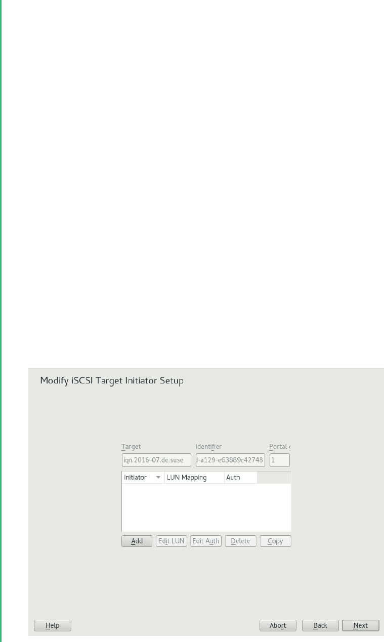
3.
Click Add, then define a new iSCSI LIO target group and devices:
The iSCSI LIO Target software automatically completes the Target, Identifier, Portal Group,
IP Address, and Port Number elds. Use Authentication is selected by default.
a.
If you have multiple network interfaces, use the IP address drop-down box to select
the IP address of the network interface to use for this target group. To make the
server accessible under all addresses, choose Bind All IP Addresses.
b.
Deselect Use Authentication if you do not want to require initiator authentication for
this target group (not recommended).
c.
Click Add. Enter the path of the device or partition or Browse to add it. Optionally
specify a name, then click OK. The LUN number is automatically generated, begin-
ning with 0. A name is automatically generated if you leave the eld empty.
d.
(Optional) Repeat the previous steps to add targets to this target group.
e.
After all desired targets have been added to the group, click Next.
4.
On the Modify iSCSI Target Initiator Setup page, configure information for the initiators that
are permitted to access LUNs in the target group:
163 Setting up an iSCSI LIO target group SLES 15 SP5

After you specify at least one initiator for the target group, the Edit LUN, Edit Auth, Delete,
and Copy buttons are enabled. You can use Add or Copy to add initiators for the target
group:
MODIFY ISCSI TARGET: OPTIONS
Add: Add a new initiator entry for the selected iSCSI LIO target group.
Edit LUN: Configure which LUNs in the iSCSI LIO target group to map to a selected
initiator. You can map each of the allocated targets to a preferred initiator.
Edit auth: Configure the preferred authentication method for a selected initiator.
You can specify no authentication, or you can configure incoming authentication,
outgoing authentication, or both.
Delete: Remove a selected initiator entry from the list of initiators allocated to the
target group.
Copy: Add a new initiator entry with the same LUN mappings and authentication
settings as a selected initiator entry. This allows you to easily allocate the same
shared LUNs, in turn, to each node in a cluster.
a.
Click Add, specify the initiator name, select or deselect the Import LUNs from TPG
check box, then click OK to save the settings.
b.
Select an initiator entry, click Edit LUN, modify the LUN mappings to specify which
LUNs in the iSCSI LIO target group to allocate to the selected initiator, then click
OK to save the changes.
If the iSCSI LIO target group consists of multiple LUNs, you can allocate one or
multiple LUNs to the selected initiator. By default, each of the available LUNs in the
group are assigned to an initiator LUN.
To modify the LUN allocation, perform one or more of the following actions:
Add: Click Add to create a new Initiator LUN entry, then use the Change drop-
down box to map a target LUN to it.
Delete: Select the Initiator LUN entry, then click Delete to remove a target LUN
mapping.
Change: Select the Initiator LUN entry, then use the Change drop-down box to
select which Target LUN to map to it.
164 Setting up an iSCSI LIO target group SLES 15 SP5

Typical allocation plans include the following:
A single server is listed as an initiator. All of the LUNs in the target group are
allocated to it.
You can use this grouping strategy to logically group the iSCSI SAN storage
for a given server.
Multiple independent servers are listed as initiators. One or multiple target
LUNs are allocated to each server. Each LUN is allocated to only one server.
You can use this grouping strategy to logically group the iSCSI SAN storage for
a given department or service category in the data center.
Each node of a cluster is listed as an initiator. All of the shared target LUNs are
allocated to each node. All nodes are attached to the devices, but for most le
systems, the cluster software locks a device for access and mounts it on only
one node at a time. Shared le systems (such as OCFS2) make it possible for
multiple nodes to concurrently mount the same le structure and to open the
same les with read and write access.
You can use this grouping strategy to logically group the iSCSI SAN storage for
a given server cluster.
c.
Select an initiator entry, click Edit Auth, specify the authentication settings for the
initiator, then click OK to save the settings.
You can require No Discovery Authentication, or you can configure Authentication by
Initiators, Outgoing Authentication, or both. You can specify only one user name and
password pair for each initiator. The credentials can be different for incoming and
outgoing authentication for an initiator. The credentials can be different for each
initiator.
d.
Repeat the previous steps for each iSCSI initiator that can access this target group.
e.
After the initiator assignments are configured, click Next.
5.
Click Finish to save and apply the settings.
165 Setting up an iSCSI LIO target group SLES 15 SP5
15.2.5 Modifying an iSCSI LIO target group
You can modify an existing iSCSI LIO target group as follows:
Add or remove target LUN devices from a target group
Add or remove initiators for a target group
Modify the initiator LUN-to-target LUN mappings for an initiator of a target group
Modify the user name and password credentials for an initiator authentication (incoming,
outgoing, or both)
To view or modify the settings for an iSCSI LIO target group:
1.
Start YaST and launch Network Services iSCSI LIO Target.
2.
Switch to the Targets tab.
3.
Select the iSCSI LIO target group to be modified, then click Edit.
4.
On the Modify iSCSI Target LUN Setup page, add LUNs to the target group, edit the LUN
assignments, or remove target LUNs from the group. After all desired changes have been
made to the group, click Next.
For option information, see Modify iSCSI target: options.
5.
On the Modify iSCSI Target Initiator Setup page, configure information for the initiators
that are permitted to access LUNs in the target group. After all desired changes have been
made to the group, click Next.
6.
Click Finish to save and apply the settings.
15.2.6 Deleting an iSCSI LIO target group
Deleting an iSCSI LIO target group removes the definition of the group, and the related setup for
initiators, including LUN mappings and authentication credentials. It does not destroy the data
on the partitions. To give initiators access again, you can allocate the target LUNs to a different
or new target group, and configure the initiator access for them.
1.
Start YaST and launch Network Services iSCSI LIO Target.
166 Modifying an iSCSI LIO target group SLES 15 SP5

2.
Switch to the Targets tab.
3.
Select the iSCSI LIO target group to be deleted, then click Delete.
4.
When you are prompted, click Continue to confirm the deletion, or click Cancel to cancel it.
5.
Click Finish to save and apply the settings.
15.3 Configuring iSCSI initiator
The iSCSI initiator can be used to connect to any iSCSI target. This is not restricted to the iSCSI
target solution explained in Section15.2, “Setting up an iSCSI LIO target server”. The configuration of
iSCSI initiator involves two major steps: the discovery of available iSCSI targets and the setup
of an iSCSI session. Both can be done with YaST.
15.3.1 Using YaST for the iSCSI initiator configuration
The iSCSI Initiator Overview in YaST is divided into three tabs:
Service:
The Service tab can be used to enable the iSCSI initiator at boot time. It also offers to set
a unique Initiator Name and an iSNS server to use for the discovery.
Connected targets:
The Connected Targets tab gives an overview of the currently connected iSCSI targets. Like
the Discovered Targets tab, it also gives the option to add new targets to the system.
Discovered targets:
The Discovered Targets tab provides the possibility of manually discovering iSCSI targets
in the network.
15.3.1.1 Configuring the iSCSI initiator
1.
Start YaST and launch Network Services iSCSI Initiator.
2.
Switch to the Service tab.
167 Configuring iSCSI initiator SLES 15 SP5

3.
Under After writing configuration, define what to do if there is a configuration change. Bear
in mind that available options depend on the service current status.
The Keep current state option keeps the service in the same status.
4.
In the After reboot menu specify action that will take place after reboot:
Start on boot - to start the service automatically on boot.
Start on demand - the associated socket will be running and if needed, the service
will be started.
Do not start - the service is not started automatically.
Keep current settings - the service configuration is not changed.
5.
Specify or verify the Initiator Name.
Specify a well-formed iSCSI qualified name (IQN) for the iSCSI initiator on this server.
The initiator name must be globally unique on your network. The IQN uses the following
general format:
iqn.yyyy-mm.com.mycompany:n1:n2
where n1 and n2 are alphanumeric characters. For example:
iqn.1996-04.de.suse:01:a5dfcea717a
168 Using YaST for the iSCSI initiator configuration SLES 15 SP5

The Initiator Name is automatically completed with the corresponding value from the /
etc/iscsi/initiatorname.iscsi le on the server.
If the server has iBFT (iSCSI Boot Firmware Table) support, the Initiator Name is completed
with the corresponding value in the IBFT, and you are not able to change the initiator name
in this interface. Use the BIOS Setup to modify it instead. The iBFT is a block of information
containing various parameters useful to the iSCSI boot process, including iSCSI target and
initiator descriptions for the server.
6.
Use either of the following methods to discover iSCSI targets on the network.
iSNS: To use iSNS (Internet Storage Name Service) for discovering iSCSI targets,
continue with Section15.3.1.2, “Discovering iSCSI targets by using iSNS”.
Discovered targets: To discover iSCSI target devices manually, continue with Sec-
tion15.3.1.3, “Discovering iSCSI targets manually”.
15.3.1.2 Discovering iSCSI targets by using iSNS
Before you can use this option, you must have already installed and configured an iSNS server
in your environment. For information, see Chapter14, iSNS for Linux.
1.
In YaST, select iSCSI Initiator, then select the Service tab.
2.
Specify the IP address of the iSNS server and port. The default port is 3205.
3.
Click OK to save and apply your changes.
15.3.1.3 Discovering iSCSI targets manually
Repeat the following process for each of the iSCSI target servers that you want to access from
the server where you are setting up the iSCSI initiator.
1.
In YaST, select iSCSI Initiator, then select the Discovered Targets tab.
2.
Click Discovery to open the iSCSI Initiator Discovery dialog.
3.
Enter the IP address and change the port if needed. The default port is 3260.
4.
If authentication is required, deselect No Discovery Authentication, then specify the creden-
tials for Authentication by Initiator or Authentication by Targets.
169 Using YaST for the iSCSI initiator configuration SLES 15 SP5

5.
Click Next to start the discovery and connect to the iSCSI target server.
6.
If credentials are required, after a successful discovery, use Connect to activate the target.
You are prompted for authentication credentials to use the selected iSCSI target.
7.
Click Next to finish the configuration.
The target now appears in Connected Targets and the virtual iSCSI device is now available.
8.
Click OK to save and apply your changes.
9.
You can nd the local device path for the iSCSI target device by using the lsscsi com-
mand.
15.3.1.4 Setting the start-up preference for iSCSI target devices
1.
In YaST, select iSCSI Initiator, then select the Connected Targets tab to view a list of the
iSCSI target devices that are currently connected to the server.
2.
Select the iSCSI target device that you want to manage.
3.
Click Toggle Start-Up to modify the setting:
Automatic: This option is used for iSCSI targets that are to be connected when the iSCSI
service itself starts up. This is the typical configuration.
Onboot: This option is used for iSCSI targets that are to be connected during boot; that
is, when root ( / ) is on iSCSI. As such, the iSCSI target device will be evaluated from the
initrd on server boots. This option is ignored on platforms that cannot boot from iSCSI,
such as IBMZ. Therefore it should not be used on these platforms; use Automatic instead.
4.
Click OK to save and apply your changes.
15.3.2 Setting up the iSCSI initiator manually
Both the discovery and the configuration of iSCSI connections require a running iscsid. When
running the discovery the rst time, the internal database of the iSCSI initiator is created in the
directory /etc/iscsi/ .
170 Setting up the iSCSI initiator manually SLES 15 SP5

If your discovery is password protected, provide the authentication information to iscsid. Be-
cause the internal database does not exist when doing the rst discovery, it cannot be used now.
Instead, the configuration le /etc/iscsid.conf must be edited to provide the information.
To add your password information for the discovery, add the following lines to the end of /
etc/iscsid.conf :
discovery.sendtargets.auth.authmethod = CHAP
discovery.sendtargets.auth.username = USERNAME
discovery.sendtargets.auth.password = PASSWORD
The discovery stores all received values in an internal persistent database. In addition, it displays
all detected targets. Run this discovery with the following command:
> sudo iscsiadm -m discovery --type=st --portal=TARGET_IP
The output should look like the following:
10.44.171.99:3260,1 iqn.2006-02.com.example.iserv:systems
To discover the available targets on an iSNS server, use the following command:
sudo iscsiadm --mode discovery --type isns --portal TARGET_IP
For each target defined on the iSCSI target, one line appears. For more information about the
stored data, see Section15.3.3, “The iSCSI initiator databases”.
The special --login option of iscsiadm creates all needed devices:
> sudo iscsiadm -m node -n iqn.2006-02.com.example.iserv:systems --login
The newly generated devices show up in the output of lsscsi and can now be mounted.
15.3.3 The iSCSI initiator databases
All information that was discovered by the iSCSI initiator is stored in two database les that
reside in /etc/iscsi . There is one database for the discovery of targets and one for the dis-
covered nodes. When accessing a database, you rst must select if you want to get your data
from the discovery or from the node database. Do this with the -m discovery and -m node
parameters of iscsiadm . Using iscsiadm with one of these parameters gives an overview of
the stored records:
> sudo iscsiadm -m discovery
10.44.171.99:3260,1 iqn.2006-02.com.example.iserv:systems
171 The iSCSI initiator databases SLES 15 SP5

The target name in this example is iqn.2006-02.com.example.iserv:systems . This name is
needed for all actions that relate to this special data set. To examine the content of the data
record with the ID iqn.2006-02.com.example.iserv:systems , use the following command:
> sudo iscsiadm -m node --targetname iqn.2006-02.com.example.iserv:systems
node.name = iqn.2006-02.com.example.iserv:systems
node.transport_name = tcp
node.tpgt = 1
node.active_conn = 1
node.startup = manual
node.session.initial_cmdsn = 0
node.session.reopen_max = 32
node.session.auth.authmethod = CHAP
node.session.auth.username = joe
node.session.auth.password = ********
node.session.auth.username_in = EMPTY
node.session.auth.password_in = EMPTY
node.session.timeo.replacement_timeout = 0
node.session.err_timeo.abort_timeout = 10
node.session.err_timeo.reset_timeout = 30
node.session.iscsi.InitialR2T = No
node.session.iscsi.ImmediateData = Yes
....
To edit the value of one of these variables, use the command iscsiadm with the update op-
eration. For example, if you want iscsid to log in to the iSCSI target when it initializes, set the
variable node.startup to the value automatic :
sudo iscsiadm -m node -n iqn.2006-02.com.example.iserv:systems \
-p ip:port --op=update --name=node.startup --value=automatic
Remove obsolete data sets with the delete operation. If the target iqn.2006-02.com.exam-
ple.iserv:systems is no longer a valid record, delete this record with the following command:
> sudo iscsiadm -m node -n iqn.2006-02.com.example.iserv:systems \
-p ip:port --op=delete
Important: No confirmation
Use this option with caution because it deletes the record without any additional confir-
mation prompt.
To get a list of all discovered targets, run the sudo iscsiadm -m node command.
172 The iSCSI initiator databases SLES 15 SP5

15.4 Setting up software targets using targetcli-fb
targetcli is a shell for managing the configuration of the LinuxIO (LIO) target subsystem.
The shell can be called interactively, or you can execute one command at a time, much like
a conventional shell. Similar to a conventional shell, you can traverse the targetcli functional
hierarchy using the cd command and list contents with the ls command.
The available commands depend on the current directory. While each directory has its own set
of commands, there are also commands that are available in all directories (for example, the
cd and ls commands).
targetcli commands have the following format:
[DIRECTORY] command [ARGUMENTS]
You can use the help command in any directory to view a list of available commands or infor-
mation about any command in particular.
The targetcli tool is part of the targetcli-fb package. This package is available in the
official SUSE Linux Enterprise Server software repository, and it can be installed using the fol-
lowing command:
> sudo zypper install targetcli-fb
After the targetcli-fb package has been installed, enable the targetcli service:
> sudo systemctl enable targetcli
> sudo systemctl start targetcli
To switch to the targetcli shell, run the targetcli as root:
> sudo targetcli
You can then run the ls command to see the default configuration.
/> ls
o- / ............................ [...]
o- backstores ................. [...]
| o- block ..... [Storage Objects: 0]
| o- fileio .... [Storage Objects: 0]
| o- pscsi ..... [Storage Objects: 0]
| o- ramdisk ... [Storage Objects: 0]
| o- rbd ....... [Storage Objects: 0]
o- iscsi ............... [Targets: 0]
o- loopback ............ [Targets: 0]
o- vhost ............... [Targets: 0]
173 Setting up software targets using targetcli-fb SLES 15 SP5

o- xen-pvscsi .......... [Targets: 0]
/>
As the output of the ls command indicates, there are no configured back-ends. So the rst step
is to configure one of the supported software targets.
targetcli supports the following back-ends:
fileio , local image le
block , block storage on a dedicated disk or partition
pscsi , SCSI pass-through devices
ramdisk , memory-based back-end
rbd , Ceph RADOS block devices
To familiarize yourself with the functionality of targetcli, set up a local image le as a software
target using the create command:
/backstores/fileio create test-disc /alt/test.img 1G
This creates a 1GB test.img image in the specified location (in this case /alt ). Run ls , and
you should see the following result:
/> ls
o- / ........................................................... [...]
o- backstores ................................................ [...]
| o- block .................................... [Storage Objects: 0]
| o- fileio ................................... [Storage Objects: 1]
| | o- test-disc ... [/alt/test.img (1.0GiB) write-back deactivated]
| | o- alua ...... .......................... [ALUA Groups: 1]
| | o- default_tg_pt_gp .... [ALUA state: Active/optimized]
| o- pscsi .................................... [Storage Objects: 0]
| o- ramdisk .................................. [Storage Objects: 0]
| o- rbd ...................................... [Storage Objects: 0]
o- iscsi .............................................. [Targets: 0]
o- loopback ........................................... [Targets: 0]
o- vhost .............................................. [Targets: 0]
o- xen-pvscsi ......................................... [Targets: 0]
/>
The output indicates that there is now a le-based backstore, under the /backstores/fileio
directory, called test-disc , which is linked to the created le /alt/test.img . Note that the
new backstore is not yet activated.
174 Setting up software targets using targetcli-fb SLES 15 SP5

The next step is to connect an iSCSI target front-end to the back-end storage. Each target must
have an IQN (iSCSI Qualified Name). The most commonly used IQN format is as follows:
iqn.YYYY-MM.NAMING-AUTHORITY:UNIQUE-NAME
The following parts of an IQN are required:
YYYY-MM , the year and month when the naming authority was established
NAMING-AUTHORITY , reverse-syntax of the Internet Domain Name of the naming authority
UNIQUE-NAME , a domain-unique name chosen by the naming authority
For example, for the domain open-iscsi.com , the IQN can be as follows:
iqn.2005-03.com.open-iscsi:UNIQUE-NAME
When creating an iSCSI target, the targetcli command allows you to assign your own IQN,
as long as it follows the specified format. You can also let the command create an IQN for you
by omitting a name when creating the target, for example:
/> iscsi/ create
Run the ls command again:
/> ls
o- / ............................................................... [...]
o- backstores .................................................... [...]
| o- block ........................................ [Storage Objects: 0]
| o- fileio ....................................... [Storage Objects: 1]
| | o- test-disc ....... [/alt/test.img (1.0GiB) write-back deactivated]
| | o- alua ......................................... [ALUA Groups: 1]
| | o- default_tg_pt_gp ............. [ALUA state: Active/optimized]
| o- pscsi ........................................ [Storage Objects: 0]
| o- ramdisk ...................................... [Storage Objects: 0]
| o- rbd .......................................... [Storage Objects: 0]
o- iscsi .................................................. [Targets: 1]
| o- iqn.2003-01.org.linux-iscsi.e83.x8664:sn.8b35d04dd456 ... [TPGs: 1]
| o- tpg1 ..................................... [no-gen-acls, no-auth]
| o- acls ................................................ [ACLs: 0]
| o- luns ................................................ [LUNs: 0]
| o- portals .......................................... [Portals: 1]
| o- 0.0.0.0:3260 ........................................... [OK]
o- loopback ............................................... [Targets: 0]
o- vhost .................................................. [Targets: 0]
o- xen-pvscsi ............................................. [Targets: 0]
/>
175 Setting up software targets using targetcli-fb SLES 15 SP5

The output shows the created iSCSI target node with its automatically generated IQN
iqn.2003-01.org.linux-iscsi.e83.x8664:sn.8b35d04dd456
Note that targetcli has also created and enabled the default target portal group tpg1 . This
is done because the variables auto_add_default_portal and auto_enable_tpgt at the root
level are set to true by default.
The command also created the default portal with the 0.0.0.0 IPv4 wildcard. This means that
any IPv4 address can access the configured target.
The next step is to create a LUN (Logical Unit Number) for the iSCSI target. The best way to
do this is to let targetcli assign its name and number automatically. Switch to the directory
of the iSCSI target, and then use the create command in the lun directory to assign a LUN
to the backstore.
/> cd /iscsi/iqn.2003-01.org.linux-iscsi.e83.x8664:sn.8b35d04dd456/
/iscsi/iqn.2003-01.org.linux-iscsi.e83.x8664:sn.8b35d04dd456> cd tpg1
/iscsi/iqn.2003-01.org.linux-iscsi.e83.x8664:sn.8b35d04dd456/tpg1> luns/
create /backstores/fileio/test-disc
Run the ls command to see the changes:
/iscsi/iqn.2003-01.org.linux-iscsi.e83.x8664:sn.8b35d04dd456/tpg1> ls
o- tpg1 .............................................. [no-gen-acls, no-auth]
o- acls ..................................................... [ACLs: 0]
o- luns ..................................................... [LUNs: 1]
| o- lun0 ....... [fileio/test-disc (/alt/test.img) (default_tg_pt_gp)]
o- portals ............................................... [Portals: 1]
o- 0.0.0.0:3260 ................................................ [OK]
There is now an iSCSI target that has a 1 GB le-based backstore. The target has the
iqn.2003-01.org.linux-iscsi.e83.x8664:sn.8b35d04dd456 name, and it can be accessed
from any network port of the system.
Finally, you need to ensure that initiators have access to the configured target. One way to do
this is to create an ACL rule for each initiator that allows them to connect to the target. In this
case, you must list each desired initiator using its IQN. The IQNs of the existing initiators can
be found in the /etc/iscsi/initiatorname.iscsi le. Use the following command to add
the desired initiator (in this case, it's iqn.1996-04.de.suse:01:54cab487975b ):
/iscsi/iqn.2003-01.org.linux-iscsi.e83.x8664:sn.8b35d04dd456/tpg1> acls/ create
iqn.1996-04.de.suse:01:54cab487975b
Created Node ACL for iqn.1996-04.de.suse:01:54cab487975b
Created mapped LUN 0.
/iscsi/iqn.2003-01.org.linux-iscsi.e83.x8664:sn.8b35d04dd456/tpg1>
176 Setting up software targets using targetcli-fb SLES 15 SP5

Alternatively, you can run the target in a demo mode with no access restrictions. This method
is less secure, but it can be useful for demonstration purposes and running on closed networks.
To enable the demo mode, use the following commands:
/iscsi/iqn.2003-01.org.linux-iscsi.e83.x8664:sn.8b35d04dd456/tpg1> set attribute
generate_node_acls=1
/iscsi/iqn.2003-01.org.linux-iscsi.e83.x8664:sn.8b35d04dd456/tpg1> set attribute
demo_mode_write_protect=0
The last step is to save the created configuration using the saveconfig command available in
the root directory:
/> saveconfig /etc/target/example.json
If at some point you need to restore configuration from the saved le, you need to clear the
current configuration rst. Keep in mind that clearing the current configuration results in data
loss unless you save your configuration rst. Use the following command to clear and reload
the configuration:
/> clearconfig
As a precaution, confirm=True needs to be set
/> clearconfig confirm=true
All configuration cleared
/> restoreconfig /etc/target/example.json
Configuration restored from /etc/target/example.json
/>
To test whether the configured target is working, connect to it using the open-iscsi iSCSI ini-
tiator installed on the same system (replace HOSTNAME with the host name of the local machine):
> iscsiadm -m discovery -t st -p HOSTNAME
This command returns a list of found targets, for example:
192.168.20.3:3260,1 iqn.2003-01.org.linux-iscsi.e83.x8664:sn.8b35d04dd456
You can then connect to the listed target using the login iSCSI command. This makes the target
available as a local disk.
15.5 Using iSCSI disks when installing
Booting from an iSCSI disk on AMD64/Intel 64 and IBM POWER architectures is supported when
iSCSI-enabled rmware is used.
177 Using iSCSI disks when installing SLES 15 SP5

To use iSCSI disks during installation, it is necessary to add the following parameter to the boot
parameter line:
withiscsi=1
During installation, an additional screen appears that provides the option to attach iSCSI disks
to the system and use them in the installation process.
Note: Mount point support
iSCSI devices will appear asynchronously during the boot process. While the initrd guar-
antees that those devices are set up correctly for the root le system, there are no such
guarantees for any other le systems or mount points like /usr . Hence any system mount
points like /usr or /var are not supported. To use those devices, ensure correct syn-
chronization of the respective services and devices.
15.6 Troubleshooting iSCSI
This section describes some known issues and possible solutions for iSCSI target and iSCSI ini-
tiator issues.
15.6.1 Portal error when setting up target LUNs on an iSCSI LIO
target server
When adding or editing an iSCSI LIO target group, you get an error:
Problem setting network portal IP_ADDRESS:3260
The /var/log/YasT2/y2log log le contains the following error:
find: `/sys/kernel/config/target/iscsi': No such file or directory
This problem occurs if the iSCSI LIO Target Server software is not currently running. To resolve
this issue, exit YaST, manually start iSCSI LIO at the command line with systemctl start
targetcli , then try again.
You can also enter the following to check if configfs , iscsi_target_mod , and tar-
get_core_mod are loaded. A sample response is shown.
> sudo lsmod | grep iscsi
178 Troubleshooting iSCSI SLES 15 SP5

iscsi_target_mod 295015 0
target_core_mod 346745 4
iscsi_target_mod,target_core_pscsi,target_core_iblock,target_core_file
configfs 35817 3 iscsi_target_mod,target_core_mod
scsi_mod 231620 16
iscsi_target_mod,target_core_pscsi,target_core_mod,sg,sr_mod,mptctl,sd_mod,
scsi_dh_rdac,scsi_dh_emc,scsi_dh_alua,scsi_dh_hp_sw,scsi_dh,libata,mptspi,
mptscsih,scsi_transport_spi
15.6.2 iSCSI LIO targets are not visible from other computers
If you use a firewall on the target server, you must open the iSCSI port that you are using to
allow other computers to see the iSCSI LIO targets. For information, see Section15.2.1, “iSCSI LIO
target service start-up and firewall settings”.
15.6.3 Data packets dropped for iSCSI traffic
A firewall might drop packets if it gets too busy. The default for the SUSE Firewall is to drop
packets after three minutes. If you nd that iSCSI traffic packets are being dropped, consider
configuring the SUSE Firewall to queue packets instead of dropping them when it gets too busy.
15.6.4 Using iSCSI volumes with LVM
Use the troubleshooting tips in this section when using LVM on iSCSI targets.
15.6.4.1 Check if the iSCSI initiator discovery occurs at boot
When you set up the iSCSI Initiator, ensure that you enable discovery at boot time so that udev
can discover the iSCSI devices at boot time and set up the devices to be used by LVM.
15.6.4.2 Check that iSCSI target discovery occurs at boot
Remember that udev provides the default setup for devices. Ensure that all of the applications
that create devices are started at boot time so that udev can recognize and assign devices for
them at system start-up. If the application or service is not started until later, udev does not
create the device automatically as it would at boot time.
179 iSCSI LIO targets are not visible from other computers SLES 15 SP5

15.6.5 iSCSI targets are mounted when the configuration file is set
to manual
When Open-iSCSI starts, it can mount the targets even if the node.startup option is set to
manual in the /etc/iscsi/iscsid.conf le if you manually modified the configuration le.
Check the /etc/iscsi/nodes/TARGET_NAME/IP_ADDRESS,PORT/default le. It contains a
node.startup setting that overrides the /etc/iscsi/iscsid.conf le. Setting the mount
option to manual by using the YaST interface also sets node.startup = manual in the /etc/
iscsi/nodes/TARGET_NAME/IP_ADDRESS,PORT/default les.
15.7 iSCSI LIO target terminology
backstore
A physical storage object that provides the actual storage underlying an iSCSI endpoint.
CDB (command descriptor block)
The standard format for SCSI commands. CDBs are commonly 6, 10, or 12 bytes long,
though they can be 16 bytes or of variable length.
CHAP (challenge handshake authentication protocol)
A point-to-point protocol (PPP) authentication method used to confirm the identity of one
computer to another. After the Link Control Protocol (LCP) connects the two computers,
and the CHAP method is negotiated, the authenticator sends a random Challenge to the
peer. The peer issues a cryptographically hashed Response that depends upon the Chal-
lenge and a secret key. The authenticator verifies the hashed Response against its own
calculation of the expected hash value, and either acknowledges the authentication or ter-
minates the connection. CHAP is defined in the RFC 1994.
CID (connection identifier)
A 16‐bit number, generated by the initiator, that uniquely identifies a connection between
two iSCSI devices. This number is presented during the login phase.
endpoint
The combination of an iSCSI Target Name with an iSCSI TPG (IQN + Tag).
180 iSCSI targets are mounted when the configuration file is set to manual SLES 15 SP5

EUI (extended unique identifier)
A 64‐bit number that uniquely identifies every device in the world. The format consists
of 24 bits that are unique to a given company, and 40 bits assigned by the company to
each device it builds.
initiator
The originating end of an SCSI session. Typically a controlling device such as a computer.
IPS (Internet protocol storage)
The class of protocols or devices that use the IP protocol to move data in a storage network.
FCIP (Fibre Channel over Internet Protocol), iFCP (Internet Fibre Channel Protocol), and
iSCSI (Internet SCSI) are all examples of IPS protocols.
IQN (iSCSI qualified name)
A name format for iSCSI that uniquely identifies every device in the world (for example:
iqn.5886.com.acme.tapedrive.sn‐a12345678 ).
ISID (initiator session identifier)
A 48‐bit number, generated by the initiator, that uniquely identifies a session between the
initiator and the target. This value is created during the login process, and is sent to the
target with a Login PDU.
MCS (multiple connections per session)
A part of the iSCSI specification that allows multiple TCP/IP connections between an ini-
tiator and a target.
MPIO (multipath I/O)
A method by which data can take multiple redundant paths between a server and storage.
network portal
The combination of an iSCSI endpoint with an IP address plus a TCP (Transmission Control
Protocol) port. TCP port 3260 is the port number for the iSCSI protocol, as defined by
IANA (Internet Assigned Numbers Authority).
SAM (SCSI architectural model)
A document that describes the behavior of SCSI in general terms, allowing for different
types of devices communicating over various media.
target
The receiving end of an SCSI session, typically a device such as a disk drive, tape drive,
or scanner.
181 iSCSI LIO target terminology SLES 15 SP5

target group (TG)
A list of SCSI target ports that are all treated the same when creating views. Creating a
view can help simplify LUN (logical unit number) mapping. Each view entry specifies a
target group, host group, and a LUN.
target port
The combination of an iSCSI endpoint with one or more LUNs.
target port group (TPG)
A list of IP addresses and TCP port numbers that determines which interfaces a specific
iSCSI target will listen to.
target session identifier (TSID)
A 16‐bit number, generated by the target, that uniquely identifies a session between the
initiator and the target. This value is created during the login process, and is sent to the
initiator with a Login Response PDU (protocol data units).
15.8 More information
The iSCSI protocol has been available for several years. There are many reviews comparing iSCSI
with SAN solutions, benchmarking performance, and there also is documentation describing
hardware solutions. For more information, see the Open-iSCSI project home page at https://
www.open-iscsi.com/ .
Additionally, see the man pages for iscsiadm , iscsid , and the example configuration le /
etc/iscsid.conf .
182 More information SLES 15 SP5

16 Fibre Channel storage over Ethernet networks:
FCoE
Many enterprise data centers rely on Ethernet for their LAN and data traffic, and on Fibre Chan-
nel networks for their storage infrastructure. Open Fibre Channel over Ethernet (FCoE) Initiator
software allows servers with Ethernet adapters to connect to a Fibre Channel storage subsystem
over an Ethernet network. This connectivity was previously reserved exclusively for systems
with Fibre Channel adapters over a Fibre Channel fabric. The FCoE technology reduces com-
plexity in the data center by aiding network convergence. This helps to preserve your existing
investments in a Fibre Channel storage infrastructure and to simplify network management.
FIGURE16.1:OPEN FIBRE CHANNEL OVER ETHERNET SAN
Open-FCoE allows you to run the Fibre Channel protocols on the host, instead of on propri-
etary hardware on the host bus adapter. It is targeted for 10 Gbps (gigabit per second) Ether-
net adapters, but can work on any Ethernet adapter that supports pause frames. The initiator
software provides a Fibre Channel protocol processing module and an Ethernet-based transport
module. The Open-FCoE module acts as a low-level driver for SCSI. The Open-FCoE transport
uses net_device to send and receive packets. Data Center Bridging (DCB) drivers provide the
quality of service for FCoE.
183 SLES 15 SP5

FCoE is an encapsulation protocol that moves the Fibre Channel protocol traffic over Ethernet
connections without changing the Fibre Channel frame. This allows your network security and
traffic management infrastructure to work the same with FCoE as it does with Fibre Channel.
You might choose to deploy FCoE in your enterprise if the following conditions exist:
Your enterprise already has a Fibre Channel storage subsystem and administrators with
Fibre Channel skills and knowledge.
You are deploying 10 Gbps Ethernet in the network.
This section describes how to set up FCoE in your network.
16.1 Configuring FCoE interfaces during the
installation
The YaST installation for SUSE Linux Enterprise Server allows you to configure FCoE disks during
the operating system installation if FCoE is enabled at the switch for the connections between the
server and the Fibre Channel storage infrastructure. Some system BIOS types can automatically
detect the FCoE disks, and report the disks to the YaST Installation software. However, automatic
detection of FCoE disks is not supported by all BIOS types. To enable automatic detection in
this case, you can add the withfcoe option to the kernel command line when you begin the
installation:
withfcoe=1
When the FCoE disks are detected, the YaST installation offers the option to configure FCoE
instances at that time. On the Disk Activation page, select Configure FCoE Interfaces to access
the FCoE configuration. For information about configuring the FCoE interfaces, see Section16.3,
“Managing FCoE services with YaST”.
184 Configuring FCoE interfaces during the installation SLES 15 SP5

Note: Mount point support
FCoE devices will appear asynchronously during the boot process. While the initrd guar-
antees that those devices are set up correctly for the root le system, there are no such
guarantees for any other le systems or mount points like /usr . Hence any system mount
points like /usr or /var are not supported. To use those devices, ensure correct syn-
chronization of the respective services and devices.
16.2 Installing FCoE and the YaST FCoE client
You can set up FCoE disks in your storage infrastructure by enabling FCoE at the switch for
the connections to a server. If FCoE disks are available when the SUSE Linux Enterprise Server
operating system is installed, the FCoE Initiator software is automatically installed at that time.
If the FCoE Initiator software and the YaST FCoE Client software are not installed, use the
following procedure to manually install them with the following command:
> sudo zypper in yast2-fcoe-client fcoe-utils
Alternatively, use the YaST Software Manager to install the packages listed above.
185 Installing FCoE and the YaST FCoE client SLES 15 SP5
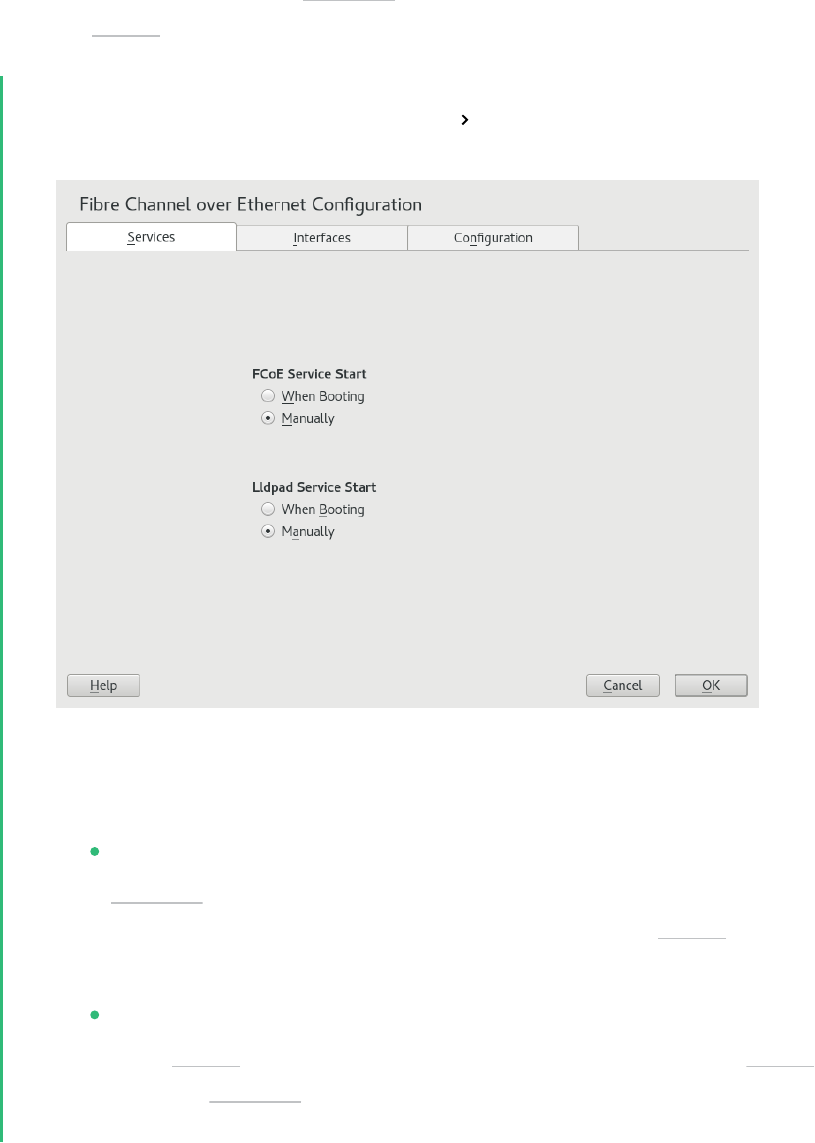
16.3 Managing FCoE services with YaST
You can use the YaST FCoE Client Configuration option to create, configure, and remove FCoE
interfaces for the FCoE disks in your Fibre Channel storage infrastructure. To use this option,
the FCoE Initiator service (the fcoemon daemon) and the Link Layer Discovery Protocol agent
daemon ( llpad ) must be installed and running, and the FCoE connections must be enabled at
the FCoE-capable switch.
1.
Launch YaST and select Network Services FCoE Client Configuration.
2.
On the Services tab, view or modify the FCoE service and Lldpad (Link Layer Discovery
Protocol agent daemon) service start time as necessary.
FCoE service start: Specifies whether to start the Fibre Channel over Ethernet service
fcoemon daemon at the server boot time or manually. The daemon controls the
FCoE interfaces and establishes a connection with the llpad daemon. The values
are When Booting (default) or Manually.
Lldpad service start: Specifies whether to start the Link Layer Discovery Protocol
agent llpad daemon at the server boot time or manually. The llpad daemon in-
forms the fcoemon daemon about the Data Center Bridging features and the config-
uration of the FCoE interfaces. The values are When Booting (default) or Manually.
186 Managing FCoE services with YaST SLES 15 SP5

If you modify a setting, click OK to save and apply the change.
3.
On the Interfaces tab, view information about all detected network adapters on the serv-
er, including information about VLAN and FCoE configuration. You can also create an
FCoE VLAN interface, change settings for an existing FCoE interface, or remove an FCoE
interface.
Use the FCoE VLAN Interface column to determine whether FCoE is available or not:
Interface Name
If a name is assigned to the interface, such as eth4.200 , FCoE is available on the
switch, and the FCoE interface is activated for the adapter.
Not configured:
If the status is not configured, FCoE is enabled on the switch, but an FCoE interface
has not been activated for the adapter. Select the adapter, then click Create FCoE
VLAN Interface to activate the interface on the adapter.
Not available:
If the status is not available, FCoE is not possible for the adapter because FCoE has
not been enabled for that connection on the switch.
4.
To set up an FCoE-enabled adapter that has not yet been configured, select it and click
Create FCoE VLAN Interface. Confirm the query with Yes.
The adapter is now listed with an interface name in the FCoE VLAN Interface column.
5.
To change the settings for an adapter that is already configured, select it from the list,
then click Change Settings.
187 Managing FCoE services with YaST SLES 15 SP5

The following options can be configured:
FCoE enable
Enable or disable the creation of FCoE instances for the adapter.
DCB required
Specifies whether Data Center Bridging is required for the adapter (usually this is
the case).
Auto VLAN
Specifies whether the fcoemon daemon creates the VLAN interfaces automatically.
If you modify a setting, click Next to save and apply the change. The settings are written
to the /etc/fcoe/cfg-ethX le. The fcoemon daemon reads the configuration les for
each FCoE interface when it is initialized.
6.
To remove an interface that is already configured, select it from the list. Click Remove
Interface and Continue to confirm. The FCoE Interface value changes to not configured.
7.
On the Configuration tab, view or modify the general settings for the FCoE system ser-
vice. You can enable or disable debugging messages from the FCoE service script and the
fcoemon daemon and specify whether messages are sent to the system log.
188 Managing FCoE services with YaST SLES 15 SP5

8.
Click OK to save and apply changes.
16.4 Configuring FCoE with commands
The following steps require using the fipvlan command. If the command is not installed, install
it by running:
> sudo zypper in fcoe-utils
To discover and configure all Ethernet interfaces, proceed as follows:
1.
Open the terminal.
2.
To discover all available Ethernet interfaces, run the following command:
> sudo fipvlan -a
3.
For each Ethernet interface where FCoE offload is configured, run the following command:
> sudo fipvlan -c -s ETHERNET_INTERFACE
The command creates a network interface if it does not exist and starts the Open-FCoE
initiator on the discovered FCoE VLAN.
16.5 Managing FCoE instances with the FCoE
administration tool
The fcoeadm utility is the Fibre Channel over Ethernet (FCoE) management tool. It can be used
to create, destroy, and reset an FCoE instance on a given network interface. The fcoeadm utility
sends commands to a running fcoemon process via a socket interface. For information about
fcoemon , see the man 8 fcoemon .
The fcoeadm utility allows you to query the FCoE instances about the following:
Interfaces
Target LUNs
Port statistics
189 Configuring FCoE with commands SLES 15 SP5

The fcoeadm utility is part of the fcoe-utils package. The general syntax for the command
looks like the following:
fcoeadm
[-c|--create] [<ethX>]
[-d|--destroy] [<ethX>]
[-r|--reset] [<ethX>]
[-S|--Scan] [<ethX>]
[-i|--interface] [<ethX>]
[-t|--target] [<ethX>]
[-l|--lun] [<ethX>]
[-s|--stats <ethX>] [<interval>]
[-v|--version]
[-h|--help]
Refer to man 8 fcoeadm for details.
Examples
fcoeadm -c eth2.101
Create an FCoE instance on eth2.101.
fcoeadm -d eth2.101
Destroy an FCoE instance on eth2.101.
fcoeadm -i eth3
Show information about all FCoE instances on interface eth3 . If no interface is specified,
information for all interfaces that have FCoE instances created will be shown. The follow-
ing example shows information on connection eth0.201:
> sudo fcoeadm -i eth0.201
Description: 82599EB 10-Gigabit SFI/SFP+ Network Connection
Revision: 01
Manufacturer: Intel Corporation
Serial Number: 001B219B258C
Driver: ixgbe 3.3.8-k2
Number of Ports: 1
Symbolic Name: fcoe v0.1 over eth0.201
OS Device Name: host8
Node Name: 0x1000001B219B258E
Port Name: 0x2000001B219B258E
190 Examples SLES 15 SP5

FabricName: 0x2001000573D38141
Speed: 10 Gbit
Supported Speed: 10 Gbit
MaxFrameSize: 2112
FC-ID (Port ID): 0x790003
State: Online
fcoeadm -l eth3.101
Show detailed information about all LUNs discovered on connection eth3.101. If no con-
nection is specified, information about all LUNs discovered on all FCoE connections will
be shown.
fcoeadm -r eth2.101
Reset the FCoE instance on eth2.101.
fcoeadm -s eth3 3
Show statistical information about a specific eth3 port that has FCoE instances, at an in-
terval of three seconds. The statistics are displayed one line per time interval. If no interval
is given, the default of one second is used.
fcoeadm -t eth3
Show information about all discovered targets from a given eth3 port having FCoE in-
stances. After each discovered target, any associated LUNs are listed. If no instance is spec-
ified, targets from all ports that have FCoE instances are shown. The following example
shows information of targets from the eth0.201 connection:
> sudo fcoeadm -t eth0.201
Interface: eth0.201
Roles: FCP Target
Node Name: 0x200000D0231B5C72
Port Name: 0x210000D0231B5C72
Target ID: 0
MaxFrameSize: 2048
OS Device Name: rport-8:0-7
FC-ID (Port ID): 0x79000C
State: Online
LUN ID Device Name Capacity Block Size Description
------ ----------- ---------- ---------- ----------------------------
40 /dev/sdqi 792.84 GB 512 IFT DS S24F-R2840-4 (rev 386C)
72 /dev/sdpk 650.00 GB 512 IFT DS S24F-R2840-4 (rev 386C)
168 /dev/sdgy 1.30 TB 512 IFT DS S24F-R2840-4 (rev 386C)
191 Examples SLES 15 SP5

16.6 More information
For information, see the follow documentation:
For information about the Open-FCoE service daemon, see the fcoemon(8) man page.
For information about the Open-FCoE Administration tool, see the fcoeadm(8) man page.
For information about the Data Center Bridging Configuration tool, see the dcbtool(8)
man page.
For information about the Link Layer Discovery Protocol agent daemon, see the lld-
pad(8) man page.
192 More information SLES 15 SP5

17 NVMe-oF
This chapter describes how to set up an NVMe over Fabrics host and target.
17.1 Overview
NVM Express® (NVMe®) is an interface standard for accessing non-volatile storage, commonly
SSD disks. NVMe supports much higher speeds and has a lower latency than SATA.
NVMe-oF™ is an architecture to access NVMe storage over different networking fabrics—for
example, RDMA, TCP, or NVMe over Fibre Channel (FC-NVMe). The role of NVMe-oF is similar
to iSCSI. To increase the fault-tolerance, NVMe-oF has a built-in support for multipathing. The
NVMe-oF multipathing is not based on the traditional DM-Multipathing.
The NVMe host is the machine that connects to an NVMe target. The NVMe target is the machine
that shares its NVMe block devices.
NVMe is supported on SUSE Linux Enterprise Server 15 SP5. There are Kernel modules available
for the NVMe block storage and NVMe-oF target and host.
To see if your hardware requires any special consideration, refer to Section17.4, “Special hardware
configuration”.
17.2 Setting up an NVMe-oF host
To use NVMe-oF, a target must be available with one of the supported networking methods.
Supported are NVMe over Fibre Channel, TCP, and RDMA. The following sections describe how
to connect a host to an NVMe target.
17.2.1 Installing command line client
To use NVMe-oF, you need the nvme command line tool. Install it with zypper :
> sudo zypper in nvme-cli
Use nvme --help to list all available subcommands. Man pages are available for nvme sub-
commands. Consult them by executing man nvme-SUBCOMMAND . For example, to view the man
page for the discover subcommand, execute man nvme-discover .
193 Overview SLES 15 SP5

17.2.2 Discovering NVMe-oF targets
To list available NVMe subsystems on the NVMe-oF target, you need the discovery controller
address and service ID.
> sudo nvme discover -t TRANSPORT -a DISCOVERY_CONTROLLER_ADDRESS -s SERVICE_ID
Replace TRANSPORT with the underlying transport medium: loop , rdma , tcp , or fc . Replace
DISCOVERY_CONTROLLER_ADDRESS with the address of the discovery controller. For RDMA and
TCP, this should be an IPv4 address. Replace SERVICE_ID with the transport service ID. If the
service is IP based, like RDMA or TCP, service ID specifies the port number. For Fibre Channel,
the service ID is not required.
The NVMe hosts only see the subsystems they are allowed to connect to.
Example:
> sudo nvme discover -t tcp -a 10.0.0.3 -s 4420
For the FC, the example looks as follows:
> sudo nvme discover --transport=fc \
--traddr=nn-0x201700a09890f5bf:pn-0x201900a09890f5bf \
--host-traddr=nn-0x200000109b579ef6:pn-0x100000109b579ef6
For more details, see man nvme-discover .
17.2.3 Connecting to NVMe-oF targets
After you have identified the NVMe subsystem, you can connect it with the nvme connect
command.
> sudo nvme connect -t transport -a DISCOVERY_CONTROLLER_ADDRESS -s SERVICE_ID -
n SUBSYSTEM_NQN
Replace TRANSPORT with the underlying transport medium: loop , rdma , tcp or fc . Replace
DISCOVERY_CONTROLLER_ADDRESS with the address of the discovery controller. For RDMA and
TCP this should be an IPv4 address. Replace SERVICE_ID with the transport service ID. If the
service is IP based, like RDMA or TCP, this specifies the port number. Replace SUBSYSTEM_NQN
with the NVMe qualified name of the desired subsystem as found by the discovery command.
NQN is the abbreviation for NVMe Qualified Name. The NQN must be unique.
194 Discovering NVMe-oF targets SLES 15 SP5

Example:
> sudo nvme connect -t tcp -a 10.0.0.3 -s 4420 -n nqn.2014-08.com.example:nvme:nvm-
subsystem-sn-d78432
For the FC, the example looks as follows:
> sudo nvme connect --transport=fc \
--traddr=nn-0x201700a09890f5bf:pn-0x201900a09890f5bf \
--host-traddr=nn-0x200000109b579ef6:pn-0x100000109b579ef6 \
--nqn=nqn.2014-08.org.nvmexpress:uuid:1a9e23dd-466e-45ca-9f43-a29aaf47cb21
Alternatively, use nvme connect-all to connect to all discovered namespaces. For advanced
usage, see man nvme-connect and man nvme-connect-all .
In case of a path loss, the NVMe subsystem tries to reconnect for a time period, defined by
the ctrl-loss-tmo option of the nvme connect command. After this time (default value is
600s), the path is removed and the upper layers of the block layer (le system) are notified. By
default, the le system is then mounted read-only, which usually is not the expected behavior.
Therefore, it is recommended to set the ctrl-loss-tmo option so that the NVMe subsystem
keeps trying to reconnect without a limit. To do so, run the following command:
> sudo nvme connect --ctrl-loss-tmo=-1
To make an NVMe over Fabrics subsystem available at boot, create a /etc/nvme/discov-
ery.conf le on the host with the parameters passed to the discover command (as described
in Section17.2.2, “Discovering NVMe-oF targets”. For example, if you use the discover command
as follows:
> sudo nvme discover -t tcp -a 10.0.0.3 -s 4420
Add the parameters of the discover command to the /etc/nvme/discovery.conf le:
echo "-t tcp -a 10.0.0.3 -s 4420" | sudo tee -a /etc/nvme/discovery.conf
Then enable the nvmf-autoconnect service:
> sudo systemctl enable nvmf-autoconnect.service
17.2.4 Multipathing
NVMe native multipathing is enabled by default. If the CMIC option in the controller identity
settings is set, the NVMe stack recognizes an NVME drive as a multipathed device by default.
195 Multipathing SLES 15 SP5

To manage the multipathing, you can use the following:
MANAGING MULTIPATHING
nvme list-subsys
Prints the layout of the multipath devices.
multipath -ll
The command has a compatibility mode and displays NVMe multipath devices. Bear in
mind that you need to enable the enable_foreign option to use the command. For details,
refer to Section18.13, “Miscellaneous options”.
nvme-core.multipath=N
When the option is added as a boot parameter, the NVMe native multipathing will be
disabled.
17.3 Setting up an NVMe-oF target
17.3.1 Installing command line client
To configure an NVMe-oF target, you need the nvmetcli command line tool. Install it with
zypper :
> sudo zypper in nvmetcli
The current documentation for nvmetcli is available at https://git.infradead.org/users/hch/
nvmetcli.git/blob_plain/HEAD:/Documentation/nvmetcli.txt .
17.3.2 Configuration steps
The following procedure provides an example of how to set up an NVMe-oF target.
The configuration is stored in a tree structure. Use the command cd to navigate. Use ls to list
objects. You can create new objects with create .
1.
Start the nvmetcli interactive shell:
> sudo nvmetcli
196 Setting up an NVMe-oF target SLES 15 SP5

2.
Create a new port:
(nvmetcli)> cd ports
(nvmetcli)> create 1
(nvmetcli)> ls 1/
o- 1
o- referrals
o- subsystems
3.
Create an NVMe subsystem:
(nvmetcli)> cd /subsystems
(nvmetcli)> create nqn.2014-08.org.nvmexpress:NVMf:uuid:c36f2c23-354d-416c-95de-
f2b8ec353a82
(nvmetcli)> cd nqn.2014-08.org.nvmexpress:NVMf:uuid:c36f2c23-354d-416c-95de-
f2b8ec353a82/
(nvmetcli)> ls
o- nqn.2014-08.org.nvmexpress:NVMf:uuid:c36f2c23-354d-416c-95de-f2b8ec353a82
o- allowed_hosts
o- namespaces
4.
Create a new namespace and set an NVMe device to it:
(nvmetcli)> cd namespaces
(nvmetcli)> create 1
(nvmetcli)> cd 1
(nvmetcli)> set device path=/dev/nvme0n1
Parameter path is now '/dev/nvme0n1'.
5.
Enable the previously created namespace:
(nvmetcli)> cd ..
(nvmetcli)> enable
The Namespace has been enabled.
6.
Display the created namespace:
(nvmetcli)> cd ..
(nvmetcli)> ls
o- nqn.2014-08.org.nvmexpress:NVMf:uuid:c36f2c23-354d-416c-95de-f2b8ec353a82
o- allowed_hosts
o- namespaces
o- 1
7.
Allow all hosts to use the subsystem. Only do this in secure environments.
(nvmetcli)> set attr allow_any_host=1
197 Configuration steps SLES 15 SP5

Parameter allow_any_host is now '1'.
Alternatively, you can allow only specific hosts to connect:
(nvmetcli)> cd nqn.2014-08.org.nvmexpress:NVMf:uuid:c36f2c23-354d-416c-95de-
f2b8ec353a82/allowed_hosts/
(nvmetcli)> create hostnqn
8.
List all created objects:
(nvmetcli)> cd /
(nvmetcli)> ls
o- /
o- hosts
o- ports
| o- 1
| o- referrals
| o- subsystems
o- subsystems
o- nqn.2014-08.org.nvmexpress:NVMf:uuid:c36f2c23-354d-416c-95de-f2b8ec353a82
o- allowed_hosts
o- namespaces
o- 1
9.
Make the target available via TCP. Use trtype=rdma for RDMA:
(nvmetcli)> cd ports/1/
(nvmetcli)> set addr adrfam=ipv4 trtype=tcp traddr=10.0.0.3 trsvcid=4420
Parameter trtype is now 'tcp'.
Parameter adrfam is now 'ipv4'.
Parameter trsvcid is now '4420'.
Parameter traddr is now '10.0.0.3'.
Alternatively, you can make it available with Fibre Channel:
(nvmetcli)> cd ports/1/
(nvmetcli)> set addr adrfam=fc trtype=fc
traddr=nn-0x1000000044001123:pn-0x2000000055001123 trsvcid=none
10.
Link the subsystem to the port:
(nvmetcli)> cd /ports/1/subsystems
(nvmetcli)> create nqn.2014-08.org.nvmexpress:NVMf:uuid:c36f2c23-354d-416c-95de-
f2b8ec353a82
198 Configuration steps SLES 15 SP5

Now you can verify that the port is enabled using dmesg :
# dmesg
...
[ 257.872084] nvmet_tcp: enabling port 1 (10.0.0.3:4420)
17.3.3 Back up and restore target configuration
You can save the target configuration in a JSON le with the following commands:
> sudo nvmetcli
(nvmetcli)> saveconfig nvme-target-backup.json
To restore the configuration, use:
(nvmetcli)> restore nvme-target-backup.json
You can also wipe the current configuration:
(nvmetcli)> clear
17.4 Special hardware configuration
17.4.1 Overview
Some hardware needs special configuration to work correctly. Skim the titles of the following
sections to see if you are using any of the mentioned devices or vendors.
17.4.2 Broadcom
If you are using the Broadcom Emulex LightPulse Fibre Channel SCSI driver, add a Kernel config-
uration parameter on the target and host for the lpfc module:
> sudo echo "options lpfc lpfc_enable_fc4_type=3" > /etc/modprobe.d/lpfc.conf
Make sure that the Broadcom adapter rmware has at least version 11.4.204.33. Also make sure
that you have the current versions of nvme-cli , nvmetcli and the Kernel installed.
199 Back up and restore target configuration SLES 15 SP5

To enable a Fibre Channel port as an NVMe target, an additional module parameter needs to
be configured: lpfc_enable_nvmet= COMMA_SEPARATED_WWPNS . Enter the WWPN with a lead-
ing 0x , for example lpfc_enable_nvmet=0x2000000055001122,0x2000000055003344 . Only
listed WWPNs will be configured for target mode. A Fibre Channel port can either be configured
as target or as initiator.
17.4.3 Marvell
FC-NVMe is supported on QLE269x and QLE27xx adapters. FC-NVMe support is enabled by
default in the Marvell® QLogic® QLA2xxx Fibre Channel driver.
To confirm NVMe is enabled, run the following command:
> cat /sys/module/qla2xxx/parameters/ql2xnvmeenable
A resulting 1 means NVMe is enabled, a 0 indicates it is disabled.
Next, ensure that the Marvell adapter rmware is at least version 8.08.204 by checking the
output of the following command:
> cat /sys/class/scsi_host/host0/fw_version
Last, ensure that the latest versions available for SUSE Linux Enterprise Server of nvme-cli ,
QConvergeConsoleCLI , and the Kernel are installed. You may, for example, run
# zypper lu && zypper pchk
to check for updates and patches.
For more details on installation, please refer to the FC-NVMe sections in the following Marvell
user guides:
https://
driverdownloads.qlogic.com/QLogicDriverDownloads_UI/ShowEula.aspx?resourcei-
d=32769&docid=96728&ProductCategory=39&Product=1259&Os=126
https://
driverdownloads.qlogic.com/QLogicDriverDownloads_UI/ShowEula.aspx?resourcei-
d=32761&docid=96726&ProductCategory=39&Product=1261&Os=126
200 Marvell SLES 15 SP5

17.5 Booting from NVMe-oF over TCP
SLES supports booting from NVMe-oF over TCP according to the NVM Express® Boot Specification
1.0 (https://nvmexpress.org/wp-content/uploads/NVM-Express-Boot-Specification-2022.11.15-Rati-
fied.pdf) .
The UEFI pre-boot environment can be configured to attempt NVMe-oF over TCP connections to
remote storage servers and use these for booting. The pre-boot environment creates an ACPI ta-
ble—NVMe Boot Firmware Table (NBFT) to store information about the NVMe-oF configuration
used for booting. The operating system uses this table at a later boot stage to set up networking
and NVMe-oF connections to access the root le system.
17.5.1 System requirements
To boot the system from NVMe-oF over TCP, the following requirements must be met:
SLES15 SP5 or later.
A SAN storage array supporting NVMe-oF over TCP
A host system with a BIOS that supports booting from NVMe-oF over TCP. Contact your
hardware vendor for information about support for this feature. Booting from NVMe-oF
over TCP is currently only supported on UEFI platforms.
17.5.2 Installation
To install SLES from NVMe-oF over TCP, proceed as follows:
1.
Use the host system's UEFI setup menus to configure NVMe-oF connections to be estab-
lished at boot time. Typically, you need to configure both networking (local IP addresses,
gateways, etc.) and NVMe-oF targets (remote IP address, subsystem NQN or discovery
NQN). Refer to the hardware documentaion for the configuration description. Your hard-
ware vendor may provide means to manage the BIOS configuration centrally and remote-
ly. Please contact your hardware vendor for additional information.
2.
Prepare the installation as described in Book “Deployment Guide”.
3.
Start the system installation using any supported installation method. You do not need to
use any specific boot parameters to enable installation on NVMe-oF over TCP.
201 Booting from NVMe-oF over TCP SLES 15 SP5

4.
If the BIOS has been configured correctly, the disk partitioning dialog in YaST will show
NVMe namespaces exported by the subsystems configured in the BIOS. They will be dis-
played as NVMe devices, where the tcp string indicates that the devices are connected
via the TCP transport. Install the operating system (in particular the EFI boot partition
and the root le system) on these namespaces.
5.
Complete the installation.
After installation, the system should boot from NVMe-oF over TCP automatically. If it does not,
check if the boot priority is set correctly in the BIOS setup.
The network interfaces used for booting are named nbft0 , nbft1 and so on. To get information
about the NVMe-oF boot, run the command:
# nvme nbft show
17.6 More information
For more details about the abilities of the nvme command, refer to nvme nvme-help .
The following links provide a basic introduction to NVMe and NVMe-oF:
https://nvmexpress.org/
https://www.nvmexpress.org/wp-content/uploads/NVMe_Over_Fabrics.pdf
https://storpool.com/blog/demystifying-what-is-nvmeof
202 More information SLES 15 SP5
18 Managing multipath I/O for devices
This section describes how to manage failover and path load balancing for multiple paths be-
tween the servers and block storage devices by using Multipath I/O (MPIO).
18.1 Understanding multipath I/O
Multipathing is the ability of a server to communicate with the same physical or logical block
storage device across multiple physical paths between the host bus adapters in the server and the
storage controllers for the device, typically in Fibre Channel (FC) or iSCSI SAN environments.
Linux multipathing provides connection fault tolerance and can provide load balancing across
the active connections. When multipathing is configured and running, it automatically isolates
and identifies device connection failures, and reroutes I/O to alternate connections.
Multipathing provides fault tolerance against connection failures, but not against failures of the
storage device itself. The latter is achieved with complementary techniques like mirroring.
18.1.1 Multipath terminology
Storage array
A hardware device with many disks and multiple fabrics connections (controllers) that
provides SAN storage to clients. Storage arrays typically have RAID and failover features
and support multipathing. Historically, active/passive (failover) and active/active (load-
balancing) storage array configurations were distinguished. These concepts still exist but
they are merely special cases of the concepts of path groups and access states supported
by modern hardware.
Host, host system
The computer running SUSE Linux Enterprise Server which acts as a client system for a
storage array.
Multipath map, multipath device
A set of path devices. It represents a storage volume on a storage array and is seen as a
single block device by the host system.
203 Understanding multipath I/O SLES 15 SP5

Path device
A member of a multipath map, typically a SCSI device. Each path device represents a
unique connection between the host computer and the actual storage volume, for example,
a logical unit from an iSCSI session.
WWID
“World Wide Identifier”. multipath-tools uses the WWID to determine which low-level
devices should be assembled into a multipath map. The WWID must be distinguished from
the configurable map name (see Section18.12, “Multipath device names and WWIDs”).
uevent, udev event
An event sent by the kernel to user space and processed by the udev subsystem. Uevents
are generated when devices are added or removed, or when they change their properties.
Device mapper
A framework in the Linux kernel for creating virtual block devices. I/O operations to
mapped devices are redirected to the underlying block devices. Device mappings may be
stacked. The device mapper implements its own event signaling, also known as “device
mapper events” or “dm events”.
initramfs
The initial RAM le system, also referred to as “initial RAM disk” (initrd) for historical rea-
sons (see Book “Administration Guide”, Chapter16 “Introduction to the boot process”, Section16.1
“Terminology”).
ALUA
“Asymmetric Logical Unit Access”, a concept introduced with the SCSI standard SCSI-3.
Storage volumes can be accessed via multiple ports, which are organized in port groups
with different states (active, standby, etc.). ALUA defines SCSI commands to query the port
groups and their states and change the state of a port group. Modern storage arrays that
support SCSI usually support ALUA, too.
204 Multipath terminology SLES 15 SP5

18.2 Hardware support
The multipathing drivers and tools are available on all architectures supported by SUSE Lin-
ux Enterprise Server. The generic, protocol-agnostic driver works with most multipath-capable
storage hardware on the market. Some storage array vendors provide their own multipathing
management tools. Consult the vendor’s hardware documentation to determine what settings
are required.
18.2.1 Multipath implementations: device mapper and NVMe
The traditional, generic implementation of multipathing under Linux uses the device mapper
framework. For most device types like SCSI devices, device mapper multipathing is the only
available implementation. Device mapper multipath is highly configurable and flexible.
The Linux NVM Express (NVMe) kernel subsystem implements multipathing natively in the ker-
nel. This implementation creates less computational overhead for NVMe devices, which are typ-
ically fast devices with very low latencies. Native NVMe multipathing requires no user space
component. Since SLE 15, native multipathing has been the default for NVMe multipath devices.
For details, refer to Section17.2.4, “Multipathing”.
This chapter documents device mapper multipath and its user-space component, multi-
path-tools . multipath-tools also has limited support for native NVMe multipathing (see
Section18.13, “Miscellaneous options”).
18.2.2 Storage array autodetection for multipathing
Device mapper multipath is a generic technology. Multipath device detection requires only that
the low-level (for example, SCSI) devices are detected by the kernel, and that device properties
reliably identify multiple low-level devices as being different “paths” to the same volume rather
than actually different devices.
The multipath-tools package detects storage arrays by their vendor and product names. It
provides built-in configuration defaults for a large variety of storage products. Consult the hard-
ware documentation of your storage array: some vendors provide specific recommendations for
Linux multipathing configuration.
If you need to apply changes to the built-in configuration for your storage array, read Section18.8,
“Multipath configuration”.
205 Hardware support SLES 15 SP5

Important: Disclaimer about built-in hardware properties
multipath-tools has built-in presets for many storage arrays. The existence of such
presets for a given storage product does not imply that the vendor of the storage product
has tested the product with dm-multipath , nor that the vendor endorses or supports the
use of dm-multipath with the product. Always consult the original vendor documenta-
tion for support-related questions.
18.2.3 Storage arrays that require specific hardware handlers
Some storage arrays require special commands for failover from one path to the other, or non-
standard error-handling methods. These special commands and methods are implemented by
hardware handlers in the Linux kernel. Modern SCSI storage arrays support the “Asymmetric
Logical Unit Access” (ALUA) hardware handler defined in the SCSI standard. Besides ALUA, the
SLE kernel contains hardware handlers for Netapp E-Series (RDAC), the Dell/EMC CLARiiON
CX family of arrays, and legacy arrays from HP.
Since Linux kernel 4.4, the Linux kernel has automatically detected hardware handlers for most
arrays, including all arrays supporting ALUA. The only requirement is that the device handler
modules are loaded at the time the respective devices are probed. The multipath-tools pack-
age ensures this by installing appropriate configuration les. Once a device handler is attached
to a given device, it cannot be changed anymore.
18.3 Planning for multipathing
Use the guidelines in this section when planning your multipath I/O solution.
18.3.1 Prerequisites
The storage array you use for the multipathed device must support multipathing. For more
information, see Section18.2, “Hardware support”.
You need to configure multipathing only if multiple physical paths exist between host bus
adapters in the server and host bus controllers for the block storage device.
206 Storage arrays that require specific hardware handlers SLES 15 SP5

For some storage arrays, the vendor provides its own multipathing software to manage
multipathing for the array’s physical and logical devices. In this case, you should follow
the vendor’s instructions for configuring multipathing for those devices.
When using multipathing in a virtualization environment, the multipathing is controlled
in the host server environment. Configure multipathing for the device before you assign
it to a virtual guest machine.
18.3.2 Multipath installation types
We distinguish installation types by the way the root device is handled. Section18.4, “Installing
SUSE Linux Enterprise Server on multipath systems” describes how the different setups are created
during and after installation.
18.3.2.1 Root file system on multipath (SAN-boot)
The root le system is on a multipath device. This is typically the case for diskless servers that
use SAN storage exclusively. On such systems, multipath support is required for booting, and
multipathing must be enabled in the initramfs.
18.3.2.2 Root file system on a local disk
The root le system (and possibly some other le systems) is on local storage, for example, on
a directly attached SATA disk or local RAID, but the system additionally uses le systems in the
multipath SAN storage. This system type can be configured in three different ways:
Multipath setup for local disk
All block devices are part of multipath maps, including the local disk. The root device
appears as a degraded multipath map with just one path. This configuration is created if
multipathing was enabled during the initial system installation with YaST.
Local disk is excluded from multipath
In this configuration, multipathing is enabled in the initramfs, but the root device is explic-
itly excluded from multipath (see Section18.11.1, “The blacklist section in multipath.con-
f”). Procedure18.1, “Disabling multipathing for the root disk after installation” describes how to
set up this configuration.
207 Multipath installation types SLES 15 SP5

Multipath disabled in the initramfs
This setup is created if multipathing was not enabled during the initial system installation
with YaST. This configuration is rather fragile; consider using one of the other options
instead.
18.3.3 Disk management tasks
Use third-party SAN array management tools or the user interface of your storage array to create
logical devices and assign them to hosts. Make sure to configure the host credentials correctly
on both sides.
You can add or remove volumes to a running host, but detecting the changes may require res-
canning SCSI targets and reconfiguring multipathing on the host. See Section18.14.6, “Scanning
for new devices without rebooting”.
Note: Storage processors
On some disk arrays, the storage array manages the traffic through storage processors.
One processor is active and the other one is passive until there is a failure. If you are
connected to the passive storage processor, you might not see the expected LUNs, or you
might see the LUNs but encounter I/O errors when you try to access them.
If a disk array has more than one storage processor, ensure that the SAN switch has a
connection to the active storage processor that owns the LUNs you want to access.
18.3.4 Software RAID and complex storage stacks
Multipathing is set up on top of basic storage devices such as SCSI disks. In a multi-layered
storage stack, multipathing is always the bottom layer. Other layers such as software RAID,
Logical Volume Management, block device encryption, etc. are layered on top of it. Therefore,
for each device that has multiple I/O paths and that you plan to use in a software RAID, you must
configure the device for multipathing before you attempt to create the software RAID device.
208 Disk management tasks SLES 15 SP5

18.3.5 High-availability solutions
High-availability solutions for clustering storage resources run on top of the multipathing service
on each node. Make sure that the configuration settings in the /etc/multipath.conf le on
each node are consistent across the cluster.
Make sure that multipath devices have the same name across all devices. Refer to Section18.12,
“Multipath device names and WWIDs” for details.
The Distributed Replicated Block Device (DRBD) high-availability solution for mirroring devices
across a LAN runs on top of multipathing. For each device that has multiple I/O paths and that
you plan to use in a DRDB solution, you must configure the device for multipathing before you
configure DRBD.
Special care must be taken when using multipathing together with clustering software that relies
on shared storage for fencing, such as pacemaker with sbd . See Section18.9.2, “Queuing policy
on clustered servers” for details.
18.4 Installing SUSE Linux Enterprise Server on
multipath systems
No special installation parameters are required for the installation of SUSE Linux Enterprise
Server on systems with multipath hardware.
18.4.1 Installing without connected multipath devices
You may want to perform installation on a local disk, without configuring the fabric and the
storage rst, with the intention to add multipath SAN devices to the system later. In this case, the
installation will proceed like on a non-multipath system. After installation, multipath-tools
will be installed, but the systemd service multipathd.service will be disabled. The system
will be configured as described in Multipath disabled in the initramfs in Section18.3.2.2, “Root file
system on a local disk”. Before adding SAN hardware, you will need to enable and start multi-
pathd.service . We recommend creating a blacklist entry in the /etc/multipath.conf
for the root device (see Section18.11.1, “The blacklist section in multipath.conf”).
209 High-availability solutions SLES 15 SP5

18.4.2 Installing with connected multipath devices
If multipath devices are connected to the system at installation time, YaST will detect them and
display a pop-up window asking you whether multipath should be enabled before entering the
partitioning stage.
If you select “No” at this prompt (not recommended), the installation will proceed as in Sec-
tion18.4.1, “Installing without connected multipath devices”. In the partitioning stage, do not use/
edit devices that will later be part of a multipath map.
If you select “Yes” at the multipath prompt, multipathd will run during the installation. No de-
vice will be added to the blacklist section of /etc/multipath.conf , thus all SCSI and DASD
devices, including local disks, will appear as multipath devices in the partitioning dialogs. After
installation, all SCSI and DASD devices will be multipath devices, as described in Section18.3.2.1,
“Root file system on multipath (SAN-boot)”.
PROCEDURE18.1:DISABLING MULTIPATHING FOR THE ROOT DISK AFTER INSTALLATION
This procedure assumes that you installed on a local disk and enabled multipathing during
installation, so that the root device is on multipath now, but you prefer to set up the
system as described in Local disk is excluded from multipath in Section18.3.2.2, “Root file system
on a local disk”.
1.
Check your system for /dev/mapper/... references to your local root device, and replace
them with references that will still work if the device is not a multipath map anymore (see
Section18.12.4, “Referring to multipath maps”). If the following command nds no references,
you do not need to apply changes:
> sudo grep -rl /dev/mapper/ /etc
2.
Switch to by-uuid persistent device policy for dracut (see Section18.7.4.2, “Persistent
device names in the initramfs”):
> echo 'persistent_policy="by-uuid"' | \
sudo tee /etc/dracut.conf.d/10-persistent-policy.conf
210 Installing with connected multipath devices SLES 15 SP5

3.
Determine the WWID of the root device:
> multipathd show paths format "%i %d %w %s"
0:2:0:0 sda 3600605b009e7ed501f0e45370aaeb77f IBM,ServeRAID M5210
...
This command prints all paths devices with their WWIDs and vendor/product information.
You will be able to identify the root device (here, the ServeRAID device) and note the
WWID.
4.
Create a blacklist entry in /etc/multipath.conf (see Section18.11.1, “The blacklist sec-
tion in multipath.conf”) with the WWID you just determined (do not apply these settings
just yet):
blacklist {
wwid 3600605b009e7ed501f0e45370aaeb77f
}
5.
Rebuild the initramfs:
> sudo dracut -f
6.
Reboot. Your system should boot with a non-multipath root disk.
18.5 Updating SLE on multipath systems
When updating your system online, you can proceed as described in Book “Upgrade Guide”, Chap-
ter5 “Upgrading online”.
The offline update of your system is similar to the fresh installation as described in Section18.4,
“Installing SUSE Linux Enterprise Server on multipath systems”. There is no blacklist , so if the user
selects to enable multipath, the root device will appear as a multipath device, even if it is nor-
mally not one. When dracut builds the initramfs during the update procedure, it sees a differ-
ent storage stack than it would see on the booted system. See Section18.7.4.2, “Persistent device
names in the initramfs” and Section18.12.4, “Referring to multipath maps”.
18.6 Multipath management tools
The multipathing support in SUSE Linux Enterprise Server is based on the Device Mapper Mul-
tipath module of the Linux kernel and the multipath-tools user space package.
211 Updating SLE on multipath systems SLES 15 SP5

The generic multipathing capability is handled by the Device Mapper Multipath (DM-MP) mod-
ule. For details, refer to Section18.6.1, “Device mapper multipath module”.
The packages multipath-tools and kpartx provide tools that handle automatic path discov-
ery and grouping. The tools are the following:
multipathd
The daemon to set up and monitor multipath maps, and a command-line client to commu-
nicate with the daemon process. See Section18.6.2, “The multipathd daemon”.
multipath
The command-line tool for multipath operations. See Section18.6.3, “The multipath com-
mand”.
kpartx
The command-line tool for managing “partitions” on multipath devices. See Section18.7.3,
“Partitions on multipath devices and kpartx”.
mpathpersist
The command-line tool for managing SCSI persistent reservations. See Section18.6.4, “SCSI
persistent reservations and mpathpersist”.
18.6.1 Device mapper multipath module
The Device Mapper Multipath (DM-MP) module dm-multipath.ko provides the generic multi-
pathing capability for Linux. DM-MPIO is the preferred solution for multipathing on SUSE Linux
Enterprise Server for SCSI and DASD devices, and can be used for NVMe devices as well.
Note: Using DM-MP for NVMe devices
Since SUSE Linux Enterprise Server 15, native NVMe multipathing (see Section18.2.1, “Mul-
tipath implementations: device mapper and NVMe”) has been recommended for NVMe and
used by default. To disable native NVMe multipathing and use device mapper multipath
instead (not recommended), boot with the kernel parameter nvme-core.multipath=0 .
212 Device mapper multipath module SLES 15 SP5

The Device Mapper Multipath module handles the following tasks:
Distributing load over multiple paths inside the active path group.
Noticing I/O errors on path devices, and marking these as failed, so that no I/O will be
sent to them.
Switching path groups when all paths in the active path group have failed.
Either failing or queuing I/O on the multipath device if all paths have failed, depending
on configuration.
The following tasks are handled by the user-space components in the multipath-tools pack-
age, not by the Device Mapper Multipath module:
Discovering devices representing different paths to the same storage device and assembling
multipath maps from them.
Collecting path devices with similar properties into path groups.
Monitoring path devices actively for failure or reinstantiation.
Monitoring of addition and removal of path devices.
The Device Mapper Multipath module does not provide an easy-to-use user interface for
setup and configuration.
For details about the components from the multipath-tools package, refer to Section18.6.2,
“The multipathd daemon”.
Note: Failures that multipath prevents
DM-MPIO protects against failures in the paths to the device, and not failures in the device
itself, such as media errors. The latter kind of errors must be prevented by other means,
such as replication.
18.6.2 The multipathd daemon
multipathd is the most important part of a modern Linux device mapper multipath setup. It is
normally started through the systemd service multipathd.service (see Section18.7.1, “Enabling,
starting, and stopping multipath services”).
213 The multipathd daemon SLES 15 SP5

multipathd serves the following tasks (some of them depend on the configuration):
On startup, detects path devices and sets up multipath maps from detected devices.
Monitors uevents and device mapper events, adding or removing path mappings to multi-
path maps as necessary and initiating failover or failback operations.
Sets up new maps on the y when new path devices are discovered.
Checks path devices at regular intervals to detect failure, and tests failed paths to reinstate
them if they become operational again.
When all paths fail, multipathd either fails the map, or switches the map device to queu-
ing mode for a given time interval.
Handles path state changes and switches path groups or regroups paths, as necessary.
Tests paths for “marginal” state, i.e. shaky fabrics conditions that cause path state flipping
between operational and non-operational.
Handles SCSI persistent reservation keys for path devices if configured. See Section18.6.4,
“SCSI persistent reservations and mpathpersist”.
multipathd also serves as a command-line client to process interactive commands by sending
them to the running daemon. The general syntax to send commands to the daemon is as follows:
> sudo multipathd COMMAND
or
> sudo multipathd -k'COMMAND'
There is also an interactive mode that allows sending multiple subsequent commands:
> sudo multipathd -k
Note: How multipath and multipathd work together
Many multipathd commands have multipath equivalents. For example, multipathd
show topology does the same thing as multipath -ll . The notable difference is that
the multipathd command inquires the internal state of the running multipathd daemon,
whereas multipath obtains information directly from the kernel and I/O operations.
If the multipath daemon is running, we recommend making modifications to the system
by using the multipathd commands. Otherwise, the daemon may notice configuration
changes and react to them. In some situations, the daemon might even try to undo the
214 The multipathd daemon SLES 15 SP5

applied changes. multipath automatically delegates certain possibly dangerous com-
mands, like destroying and flushing maps, to multipathd if a running daemon is detect-
ed.
The list below describes frequently used multipathd commands:
show topology
Shows the current map topology and properties. See Section18.14.2, “Interpreting multipath
I/O status”.
show paths
Shows the currently known path devices.
show paths format " FORMAT STRING "
Shows the currently known path devices using a format string. Use show wildcards to
see a list of supported format specifiers.
show maps
Shows the currently configured map devices.
show maps format FORMAT STRING
Shows the currently configured map devices using a format string. Use show wildcards
to see a list of supported format specifiers.
show config local
Shows the current configuration that multipathd is using.
reconfigure
Rereads configuration les, rescans devices, and sets up maps again. This is basically equiv-
alent to a restart of multipathd . A few options cannot be modified without a restart.
They are mentioned in the man page multipath.conf(5) . The reconfigure command
reloads only map devices that have changed in some way. To force the reloading of every
map device, use reconfigure all (available since SUSE Linux Enterprise Server15 SP4;
on previous versions, reconfigure reloaded every map).
del map MAP DEVICE NAME
Unconfigure and delete the given map device and its partitions. MAP DEVICE NAME can
be a device node name like dm-0 , a WWID, or a map name. The command fails if the
device is in use.
215 The multipathd daemon SLES 15 SP5

switchgroup map MAP DEVICE NAME group N
Switch to the path group with the given numeric index (starting at 1). This is useful for
maps with manual failback (see Section18.9, “Configuring policies for failover, queuing, and
failback”).
Additional commands are available to modify path states, enable or disable queuing, and more.
See multipathd(8) for details.
18.6.3 The multipath command
Even though multipath setup is mostly automatic and handled by multipathd , multipath is
still useful for some administration tasks. Several examples of the command usage follow:
multipath
Detects path devices and configures all multipath maps that it nds.
multipath -d
Similar to multipath , but does not set up any maps (“dry run”).
multipath DEVICENAME
Configures a specific multipath device. DEVICENAME can denote a member path device by
its device node name ( /dev/sdb ) or device number in major:minor format. Alternative-
ly, it can be the WWID or name of a multipath map.
multipath -f DEVICENAME
Unconfigures ("flushes") a multipath map and its partition mappings. The command will
fail if the map or one of its partitions is in use. See above for possible values of DEVICENAME .
multipath -F
Unconfigures ("flushes") all multipath maps and their partition mappings. The command
will fail for maps in use.
multipath -ll
Displays the status and topology of all currently configured multipath devices. See Sec-
tion18.14.2, “Interpreting multipath I/O status”.
multipath -ll DEVICENAME
Displays the status of a specified multipath device. See above for possible values of DE-
VICENAME .
216 The multipath command SLES 15 SP5

multipath -t
Shows the internal hardware table and the active configuration of multipath. Refer to
multipath.conf(5) for details about the configuration parameters.
multipath -T
Has a similar function to the multipath -t command but shows only hardware entries
matching the hardware detected on the host.
The option -v controls the verbosity of the output. The provided value overrides the verbosity
option in /etc/multipath.conf . See Section18.13, “Miscellaneous options”.
18.6.4 SCSI persistent reservations and mpathpersist
The mpathpersist utility is used to manage SCSI persistent reservations on Device Mapper
Multipath devices. Persistent reservations serve to restrict access to SCSI Logical Units to certain
SCSI initiators. In multipath configurations, it is important to use the same reservation keys for
all I_T nexuses (paths) for a given volume; otherwise, creating a reservation on one path device
would cause I/O errors on other paths.
Use this utility with the reservation_key attribute in the /etc/multipath.conf le to set
persistent reservations for SCSI devices. If (and only if) this option is set, the multipathd dae-
mon checks persistent reservations for newly discovered paths or reinstated paths.
You can add the attribute to the defaults section or the multipaths section of multi-
path.conf . For example:
multipaths {
multipath {
wwid 3600140508dbcf02acb448188d73ec97d
alias yellow
reservation_key 0x123abc
}
}
After setting the reservation_key parameter for all mpath devices applicable for persistent
management, reload the configuration using multipathd reconfigure .
Note: Using “reservation_key file”
If the special value reservation_key file is used in the defaults section of mul-
tipath.conf , reservation keys can be managed dynamically in the le /etc/multi-
path/prkeys using mpathpersist .
217 SCSI persistent reservations and mpathpersist SLES 15 SP5

This is the recommended way to handle persistent reservations with multipath maps. It
is available from SUSE Linux Enterprise Server 12 SP4.
Use the command mpathpersist to query and set persistent reservations for multipath maps
consisting of SCSI devices. Refer to the manual page mpathpersist(8) for details. The com-
mand-line options are the same as those of the sg_persist from the sg3_utils package. The
sg_persist(8) manual page explains the semantics of the options in detail.
In the following examples, DEVICE denotes a device mapper multipath device like /dev/map-
per/mpatha . The commands below are listed with long options for better readability. All op-
tions have single-letter replacements, like in mpathpersist -oGS 123abc DEVICE .
mpathpersist --in --read-keys DEVICE
Read the registered reservation keys for the device.
mpathpersist --in --read-reservation DEVICE
Show existing reservations for the device.
mpathpersist --out --register --param-sark=123abc DEVICE
Register a reservation key for the device. This will add the reservation key for all I_T
nexuses (path devices) on the host.
mpathpersist --out --reserve --param-rk=123abc --prout-type=5 DEVICE
Create a reservation of type 5 (“write exclusive - registrants only”) for the device, using
the previously registered key.
mpathpersist --out --release --param-rk=123abc --prout-type=5 DEVICE
Release a reservation of type 5 for the device.
mpathpersist --out --register-ignore --param-sark=0 DEVICE
Delete a previously existing reservation key from the device.
18.7 Configuring the system for multipathing
18.7.1 Enabling, starting, and stopping multipath services
To enable multipath services to start at boot time, run the following command:
> sudo systemctl enable multipathd
218 Configuring the system for multipathing SLES 15 SP5

To manually start the service in the running system, enter:
> sudo systemctl start multipathd
To restart the service, enter:
> sudo systemctl restart multipathd
In most situations, restarting the service is not necessary. To simply have multipathd reload
its configuration, run:
> sudo systemctl reload multipathd
To check the status of the service, enter:
> sudo systemctl status multipathd
To stop the multipath services in the current session, run:
> sudo systemctl stop multipathd multipathd.socket
Stopping the service does not remove existing multipath maps. To remove unused maps, run:
> sudo multipath -F
Warning: Keep multipathd.service enabled
We strongly recommend keeping multipathd.service always enabled and running on
systems with multipath hardware. The service does support systemd 's socket activation
mechanism, but we do not recommend that you rely on that. Multipath maps will not be
set up during boot if the service is disabled.
Note: Disabling multipath
If you need to disable multipath despite the warning above, for example, because a third-
party multipathing software is going to be deployed, proceed as follows. Be sure that
the system uses no hard-coded references to multipath devices (see Section18.15.2, “Un-
derstanding device referencing issues”).
To disable multipathing just for a single system boot, use the kernel parameter multi-
path=off . This affects both the booted system and the initramfs, which does not need
to be rebuilt in this case.
219 Enabling, starting, and stopping multipath services SLES 15 SP5

To disable multipathd services permanently, so that they will not be started on future
system boots, run the following commands:
> sudo systemctl disable multipathd multipathd.socket
> sudo dracut --force --omit multipath
(Whenever you disable or enable the multipath services, rebuild the initramfs . See
Section18.7.4, “Keeping the initramfs synchronized”.)
If you want to make sure multipath devices do not get set up, even when running mul-
tipath manually, add the following lines at the end of /etc/multipath.conf before
rebuilding the initramfs:
blacklist {
wwid .*
}
18.7.2 Preparing SAN devices for multipathing
Before configuring multipath I/O for your SAN devices, prepare the SAN devices, as necessary,
by doing the following:
Configure and zone the SAN with the vendor’s tools.
Configure permissions for host LUNs on the storage arrays with the vendor’s tools.
If SUSE Linux Enterprise Server ships no driver for the host bus adapter (HBA), install a
Linux driver from the HBA vendor. See the vendor’s specific instructions for more details.
If multipath devices are detected and multipathd.service is enabled, multipath maps should
be created automatically. If this does not happen, Section18.15.3, “Troubleshooting steps in emer-
gency mode” lists some shell commands that can be used to examine the situation. When the
LUNs are not seen by the HBA driver, check the zoning setup in the SAN. In particular, check
whether LUN masking is active and whether the LUNs are correctly assigned to the server.
If the HBA driver can see LUNs, but no corresponding block devices are created, additional
kernel parameters may be needed. See TID 3955167: Troubleshooting SCSI (LUN) Scanning Issues
in the SUSE Knowledge base at https://www.suse.com/support/kb/doc.php?id=3955167 .
220 Preparing SAN devices for multipathing SLES 15 SP5

18.7.3 Partitions on multipath devices and kpartx
Multipath maps can have partitions like their path devices. Partition table scanning and device
node creation for partitions is done in user space by the kpartx tool. kpartx is automatically
invoked by udev rules; there is usually no need to run it manually. See Section18.12.4, “Referring
to multipath maps” for ways to refer to multipath partitions.
Note: Disabling invocation of kpartx
The skip_kpartx option in /etc/multipath.conf can be used to disable invocation
of kpartx on selected multipath maps. This may be useful on virtualization hosts, for
example.
Partition tables and partitions on multipath devices can be manipulated as usual, using YaST or
tools like fdisk or parted . Changes applied to the partition table will be noted by the system
when the partitioning tool exits. If this does not work (usually because a device is busy), try
multipathd reconfigure , or reboot the system.
18.7.4 Keeping the initramfs synchronized
Important
Make sure that the initial RAM le system (initramfs) and the booted system behave
consistently regarding the use of multipathing for all block devices. Rebuild the initramfs
after applying multipath configuration changes.
If multipathing is enabled in the system, it also needs to be enabled in the initramfs and
vice versa. The only exception to this rule is the option Multipath disabled in the initramfs in
Section18.3.2.2, “Root file system on a local disk”.
The multipath configuration must be synchronized between the booted system and the initramfs.
Therefore, if you change any of the les: /etc/multipath.conf , /etc/multipath/wwids , /
etc/multipath/bindings , or other configuration les, or udev rules related to device identi-
fication, rebuild initramfs using the command:
> sudo dracut -f
221 Partitions on multipath devices and kpartx SLES 15 SP5

If the initramfs and the system are not synchronized, the system will not boot properly, and
the start-up procedure may result in an emergency shell. See Section18.15, “Troubleshooting MPIO”
for instructions on how to avoid or repair such a scenario.
18.7.4.1 Enabling or disabling multipathing in the initramfs
Special care must be taken if the initramfs is rebuilt in non-standard situations, for example,
from a rescue system or after booting with the kernel parameter multipath=off . dracut will
automatically include multipathing support in the initramfs if and only if it detects that the
root le system is on a multipath device while the initramfs is being built. In such cases, it is
necessary to enable or disable multipathing explicitly.
To enable multipath support in the initramfs , run the command:
> sudo dracut --force --add multipath
To disable multipath support in initramfs , run the command:
> sudo dracut --force --omit multipath
18.7.4.2 Persistent device names in the initramfs
When dracut generates the initramfs, it must refer to disks and partitions to be mounted in a
persistent manner, to make sure the system will boot correctly. When dracut detects multipath
devices, it will use the DM-MP device names such as
/dev/mapper/3600a098000aad73f00000a3f5a275dc8-part1
for this purpose by default. This is good if the system always runs in multipath mode. But if
the system is started without multipathing, as described in Section18.7.4.1, “Enabling or disabling
multipathing in the initramfs”, booting with such an initramfs will fail, because the /dev/mapper
devices will not exist. See Section18.12.4, “Referring to multipath maps” for another possible prob-
lem scenario, and some background information.
To prevent this from happening, change dracut 's persistent device naming policy by using the
--persistent-policy option. We recommend setting the by-uuid use policy:
> sudo dracut --force --omit multipath --persistent-policy=by-uuid
See also Procedure18.1, “Disabling multipathing for the root disk after installation” and Section18.15.2,
“Understanding device referencing issues”.
222 Keeping the initramfs synchronized SLES 15 SP5

18.8 Multipath configuration
The built-in multipath-tools defaults work well for most setups. If customizations are needed,
a configuration le needs to be created. The main configuration le is /etc/multipath.conf .
In addition, les in /etc/multipath/conf.d/ are taken into account. See Section18.8.2.1, “Ad-
ditional configuration files and precedence rules” for additional information.
Important: Vendor recommendations and built-in hardware
defaults
Some storage vendors publish recommended values for multipath options in their docu-
mentation. These values often represent what the vendor has tested in their environment
and found most suitable for the storage product. See the disclaimer in Section18.2.2, “Stor-
age array autodetection for multipathing”.
multipath-tools has built-in defaults for many storage arrays that are derived from
the published vendor recommendations. Run multipath -T to see the current settings
for your devices and compare them to vendor recommendations.
18.8.1 Creating /etc/multipath.conf
It is recommended that you create a minimal /etc/multipath.conf that just contains those
settings you want to change. In many cases, you do not need to create /etc/multipath.conf
at all.
If you prefer working with a configuration template that contains all possible configuration
directives, run:
multipath -T >/etc/multipath.conf
See also Section18.14.1, “Best practices for configuration”.
18.8.2 multipath.conf syntax
The /etc/multipath.conf le uses a hierarchy of sections, subsections and option/value pairs.
223 Multipath configuration SLES 15 SP5

White space separates tokens. Consecutive white space characters are collapsed into a
single space, unless quoted (see below).
The hash ( # ) and exclamation mark ( ! ) characters cause the rest of the line to be discarded
as a comment.
Sections and subsections are started with a section name and an opening brace ( { ) on the
same line, and end with a closing brace ( } ) on a line on its own.
Options and values are written on one line. Line continuations are unsupported.
Options and section names must be keywords. The allowed keywords are documented in
multipath.conf(5) .
Values may be enclosed in double quotes ( " ). They must be enclosed in quotes if they
contain white space or comment characters. A double quote character inside a value is
represented by a pair of double quotes ( "" ).
The values of some options are POSIX regular expressions (see regex(7) ). They are case
sensitive and not anchored, so “ bar ” matches “ rhabarber ”, but not “Barbie”.
The following example illustrates the syntax:
section {
subsection {
option1 value
option2 "complex value!"
option3 "value with ""quoted"" word"
} ! subsection end
} # section end
18.8.2.1 Additional configuration files and precedence rules
After /etc/multipath.conf , the tools read les matching the pattern /etc/multipath.con-
f.d/*.conf . The additional les follow the same syntax rules as /etc/multipath.conf . Sec-
tions and options can occur multiple times. If the same option in the same section is set in multiple
les, or on multiple lines in the same le, the last value takes precedence. Separate precedence
rules apply between multipath.conf sections. See below.
224 multipath.conf syntax SLES 15 SP5

18.8.3 multipath.conf sections
The /etc/multipath.conf le is organized into the following sections. Some options can occur
in more than one section. See multipath.conf(5) for details.
defaults
General default settings.
Important: Overriding built-in device properties
Built-in hardware-specific device properties take precedence over the settings in the
defaults section. Changes must therefore be made in the devices section or in
the overrides section.
blacklist
Lists devices to ignore. See Section18.11.1, “The blacklist section in multipath.conf”.
blacklist_exceptions
Lists devices to be multipathed even though they are matched by the blacklist. See Sec-
tion18.11.1, “The blacklist section in multipath.conf”.
devices
Settings specific to the storage controller. This section is a collection of device subsec-
tions. Values in this section override values for the same options in the defaults section,
and the built-in settings of multipath-tools .
device entries in the devices section are matched against the vendor and product of a
device using regular expressions. These entries will be “merged”, setting all options from
matching sections for the device. If the same option is set in multiple matching device
sections, the last device entry takes precedence, even if it is less “specific” than preceding
entries. This applies also if the matching entries appear in different configuration les (see
Section18.8.2.1, “Additional configuration files and precedence rules”). In the following example,
a device SOMECORP STORAGE will use fast_io_fail_tmo 15 .
devices {
device {
vendor SOMECORP
product STOR
fast_io_fail_tmo 10
}
225 multipath.conf sections SLES 15 SP5

device {
vendor SOMECORP
product .*
fast_io_fail_tmo 15
}
}
multipaths
Settings for individual multipath devices. This section is a list of multipath subsections.
Values override the defaults and devices sections.
overrides
Settings that override values from all other sections.
18.8.4 Applying multipath.conf modifications
To apply the configuration changes, run:
> sudo multipathd reconfigure
Do not forget to synchronize with the configuration in the initramfs. See Section18.7.4, “Keeping
the initramfs synchronized”.
Warning: Do not apply settings using multipath
Do not apply new settings with the multipath command while multipathd is running.
This may result in an inconsistent and possibly broken setup.
Note: Verifying a modified setup
It is possible to test modified settings rst before they are applied, by running:
> sudo multipath -d -v2
This command shows new maps to be created with the proposed topology, but not
whether maps will be removed/ushed. To obtain more information, run with increased
verbosity:
> sudo multipath -d -v3 2>&1 | less
226 Applying multipath.conf modifications SLES 15 SP5

18.9 Configuring policies for failover, queuing, and
failback
The goal of multipath I/O is to provide connectivity fault tolerance between the storage system
and the server. The desired default behavior depends on whether the server is a stand-alone
server or a node in a high-availability cluster.
This section discusses the most important multipath-tools configuration parameters for
achieving fault tolerance.
polling_interval
The time interval (in seconds) between health checks for path devices. The default is 5
seconds. Failed devices are checked at this time interval. For healthy devices, the time
interval may be increased up to max_polling_interval seconds.
detect_checker
If this is set to yes (default, recommended), multipathd automatically detects the best
path checking algorithm.
path_checker
The algorithm used to check path state. If you need to enable the checker, disable detec-
t_checker as follows:
defaults {
detect_checker no
}
The following list contains only the most important algorithms. See multipath.conf(5)
for the full list.
tur
Send TEST UNIT READY command. This is the default for SCSI devices with ALUA
support.
directio
Read a device sector using asynchronous I/O (aio).
rdac
Device-specific checker for NetAPP E-Series and similar arrays.
none
No path checking is performed.
227 Configuring policies for failover, queuing, and failback SLES 15 SP5

checker_timeout
If a device does not respond to a path checker command in the given time, it is consid-
ered failed. The default is the kernel's SCSI command timeout for the device (usually 30
seconds).
fast_io_fail_tmo
If an error on the SCSI transport layer is detected (for example on a Fibre Channel remote
port), the kernel transport layer waits for this amount of time (in seconds) for the transport
to recover. After that, the path device fails with “transport offline” state. This is very
useful for multipath, because it allows a quick path failover for a frequently occurring class
of errors. The value must match typical time scale for reconfiguration in the fabric. The
default value of 5 seconds works well for Fibre Channel. Other transports, like iSCSI, may
require longer timeouts.
dev_loss_tmo
If a SCSI transport endpoint (for example a Fibre Channel remote port) is not reachable any
more, the kernel waits for this amount of time (in seconds) for the port to reappear until
it removes the SCSI device node for good. Device node removal is a complex operation
which is prone to race conditions or deadlocks and should best be avoided. We therefore
recommend setting this to a high value. The special value infinity is supported. The
default is 10 minutes. To avoid deadlock situations, multipathd ensures that I/O queuing
(see no_path_retry ) is stopped before dev_loss_tmo expires.
no_path_retry
Determine what happens if all paths of a given multipath map have failed. The possible
values are:
fail
Fail I/O on the multipath map. This will cause I/O errors in upper layers such as
mounted le systems. The affected le systems, and possibly the entire host, will
enter degraded mode.
queue
I/O on the multipath map is queued in the device mapper layer and sent to the device
when path devices become available again. This is the safest option to avoid losing
data, but it can have negative effects if the path devices do not get reinstated for
a long time. Processes reading from the device will hang in uninterruptible sleep
( D ) state. Queued data occupies memory, which becomes unavailable for processes.
Eventually, memory will be exhausted.
228 Configuring policies for failover, queuing, and failback SLES 15 SP5

N
N is a positive integer. Keep the map device in queuing mode for N polling intervals.
When the time elapses, multipathd fails the map device. If polling_interval is
5 seconds and no_path_retry is 6, multipathd will queue I/O for approximately
6 * 5s = 30s before failing I/O on the map device.
flush_on_last_del
If set to yes and all path devices of a map are deleted (as opposed to just failed), fail all
I/O in the map before removing it. The default is no .
deferred_remove
If set to yes and all path devices of a map are deleted, wait for holders to close the le
descriptors for the map device before flushing and removing it. If paths reappear before the
last holder closed the map, the deferred remove operation will be cancelled. The default
is no .
failback
If a failed path device in an inactive path group recovers, multipathd reevaluates the
path group priorities of all path groups (see Section18.10, “Configuring path grouping and pri-
orities”). After the reevaluation, the highest-priority path group may be one of the currently
inactive path groups. This parameter determines what happens in this situation.
Important: Observe vendor recommendations
The optimal failback policy depends on the property of the storage device. It is
therefore strongly encouraged to verify failback settings with the storage vendor.
manual
Nothing happens unless the administrator runs a multipathd switchgroup (see
Section18.6.2, “The multipathd daemon”).
immediate
The highest-priority path group is activated immediately. This is often beneficial for
performance, especially on stand-alone servers, but it should not be used for arrays
on which the change of the path group is a costly operation.
229 Configuring policies for failover, queuing, and failback SLES 15 SP5

followover
Like immediate , but only perform failback when the path that has just become active
is the only healthy path in its path group. This is useful for cluster configurations: It
keeps a node from automatically failing back when another node requested a failover
before.
N
N is a positive integer. Wait for N polling intervals before activating the highest
priority path group. If the priorities change again during this time, the wait period
starts anew.
eh_deadline
Set an approximate upper limit for the time (in seconds) spent in SCSI error handling if
devices are unresponsive and SCSI commands time out without error response. When the
deadline has elapsed, the kernel will perform a full HBA reset.
After modifying the /etc/multipath.conf le, apply your settings as described in Sec-
tion18.8.4, “Applying multipath.conf modifications”.
18.9.1 Queuing policy on stand-alone servers
When you configure multipath I/O for a stand-alone server, a no_path_retry setting with
value queue protects the server operating system from receiving I/O errors as long as possible.
It queues messages until a multipath failover occurs. If “infinite” queuing is not desired (see
above), select a numeric value that is deemed high enough for the storage paths to recover under
ordinary circumstances (see above).
18.9.2 Queuing policy on clustered servers
When you configure multipath I/O for a node in a high-availability cluster, you want multipath
to report the I/O failure to trigger the resource failover instead of waiting for a multipath failover
to be resolved. In cluster environments, you must modify the no_path_retry setting so that the
cluster node receives an I/O error in relation to the cluster verification process (recommended
to be 50% of the heartbeat tolerance) if the connection is lost to the storage system. In addition,
you want the multipath failback to be set to manual or followover to avoid a ping-pong
of resources because of path failures.
230 Queuing policy on stand-alone servers SLES 15 SP5

18.10 Configuring path grouping and priorities
Path devices in multipath maps are grouped in path groups, also called priority groups. Only one
path group receives I/O at any given time. multipathd assigns priorities to path groups. Out
of the path groups with active paths, the group with the highest priority is activated according
to the configured failback policy for the map (see Section18.9, “Configuring policies for failover,
queuing, and failback”). The priority of a path group is the average of the priorities of the active
path devices in the path group. The priority of a path device is an integer value calculated from
the device properties (see the description of the prio option below).
This section describes the multipath.conf configuration parameters relevant for priority de-
termination and path grouping.
path_grouping_policy
Specifies the method used to combine paths into groups. Only the most important policies
are listed here; see multipath.conf(5) for other less frequently used values.
failover
One path per path group. This setting is useful for traditional “active/passive” storage
arrays.
multibus
All paths in one path group. This is useful for traditional “active/active” arrays.
group_by_prio
Path devices with the same path priority are grouped together. This option is useful
for modern arrays that support asymmetric access states, like ALUA. Combined with
the alua or sysfs priority algorithms, the priority groups set up by multipathd
will match the primary target port groups that the storage array reports through
ALUA-related SCSI commands.
Using the same policy names, the path grouping policy for a multipath map can be changed
temporarily with the command:
> sudo multipath -p POLICY_NAME MAP_NAME
marginal_pathgroups
If set to on or fpin , “marginal” path devices are sorted into a separate path group. This is
independent of the path grouping algorithm in use. See Section18.13.1, “Handling unreliable
(“marginal”) path devices”.
231 Configuring path grouping and priorities SLES 15 SP5

detect_prio
If this is set to yes (default, recommended), multipathd automatically detects the best
algorithm to set the priority for a storage device and ignores the prio setting. In practice,
this means using the sysfs prio algorithm if ALUA support is detected.
prio
Determines the method to derive priorities for path devices. If you override this, disable
detect_prio as follows:
defaults {
detect_prio no
}
The following list contains only the most important methods. Several other methods are
available, mainly to support legacy hardware. See multipath.conf(5) for the full list.
alua
Uses SCSI-3 ALUA access states to derive path priority values. The optional exclu-
sive_pref_bit argument can be used to change the behavior for devices that have
the ALUA “preferred primary target port group” (PREF) bit set:
prio alua
prio_args exclusive_pref_bit
If this option is set, “preferred” paths get a priority bonus over other active/optimized
paths. Otherwise, all active/optimized paths are assigned the same priority.
sysfs
Like alua , but instead of sending SCSI commands to the device, it obtains the access
states from sysfs . This causes less I/O load than alua , but is not suitable for all
storage arrays with ALUA support.
const
Uses a constant value for all paths.
path_latency
Measures I/O latency (time from I/O submission to completion) on path devices, and
assigns higher priority to devices with lower latency. See multipath.conf(5) for
details. This algorithm is still experimental.
232 Configuring path grouping and priorities SLES 15 SP5

weightedpath
Assigns a priority to paths based on their name, serial number, Host:Bus:Target:Lun
ID (HBTL), or Fibre Channel WWN. The priority value does not change over time.
The method requires a prio_args argument, see multipath.conf(5) for details.
For example:
prio weightedpath
prio_args "hbtl 2:.*:.*:.* 10 hbtl 3:.*:.*:.* 20 hbtl .* 1"
This assigns devices on SCSI host 3 a higher priority than devices on SCSI host 2,
and all others a lower priority.
prio_args
Some prio algorithms require extra arguments. These are specified in this option, with
syntax depending on the algorithm. See above.
hardware_handler
The name of a kernel module that the kernel uses to activate path devices when switching
path groups. This option has no effect with recent kernels because hardware handlers are
autodetected. See Section18.2.3, “Storage arrays that require specific hardware handlers”.
path_selector
The name of a kernel module that is used for load balancing between the paths of the
active path group. The available choices depend on the kernel configuration. For historical
reasons, the name must always be enclosed in quotes and followed by a “0” in multi-
path.conf , like this:
path_selector "queue-length 0"
service-time
Estimates the time pending I/O will need to complete on all paths, and selects the
path with the lowest value. This is the default.
historical-service-time
Estimates future service time based on the historical service time (about which it
keeps a moving average) and the number of outstanding requests. Estimates the time
pending I/O will need to complete on all paths, and selects the path with the lowest
value.
queue-length
Selects the path with the lowest number of currently pending I/O requests.
233 Configuring path grouping and priorities SLES 15 SP5

round-robin
Switches paths in round-robin fashion. The number of requests submitted to a path
before switching to the next one can be adjusted with the options rr_min_io_rq
and rr_weight .
io-affinity
This path selector currently does not work with multipath-tools .
After modifying the /etc/multipath.conf le, apply your settings as described in Sec-
tion18.8.4, “Applying multipath.conf modifications”.
18.11 Selecting devices for multipathing
On systems with multipath devices, you might want to avoid setting up multipath maps on some
devices (typically local disks). multipath-tools offers various means for configuring which
devices should be considered multipath path devices.
Note: multipath on local disks
In general, there is nothing wrong with setting up “degraded” multipath maps with just
a single device on top of local disks. It works ne and requires no extra configuration.
However, some administrators nd this confusing or generally oppose this sort of unnec-
essary multipathing. Also, the multipath layer causes a slight performance overhead. See
also Section18.3.2.2, “Root file system on a local disk”.
After modifying the /etc/multipath.conf le, apply your settings as described in Sec-
tion18.8.4, “Applying multipath.conf modifications”.
18.11.1 The blacklist section in multipath.conf
The /etc/multipath.conf le can contain a blacklist section that lists all devices that
should be ignored by multipathd and multipath . The following example illustrates possible
ways of excluding devices:
blacklist {
234 Selecting devices for multipathing SLES 15 SP5

wwid 3600605b009e7ed501f0e45370aaeb77f
1
device {
2
vendor ATA
product .*
}
protocol scsi:sas
3
property SCSI_IDENT_LUN_T10
4
devnode "!^dasd[a-z]*"
5
}
1
wwid entries are ideal for excluding specific devices, for example, the root disk.
2
This device section excludes all ATA devices (the regular expression for product matches
anything).
3
Excluding by protocol allows excluding devices using certain bus types, here SAS. Other
common protocol values are scsi:fcp , scsi:iscsi , and ccw . See multipath.conf(5)
for more. To see the protocols that paths in your systems are using, run:
> sudo multipathd show paths format "%d %P"
This form is supported since SLES15 SP1 and SLES12 SP5.
4
This property entry excludes devices that have a certain udev property (no matter what
the value of the property is).
5
Excluding devices by devnode is only recommended for classes of devices using regular ex-
pressions, like in the example, which excludes everything but DASD devices. Using this for
individual devices like sda is discouraged because device node names are not persistent.
The example illustrates special syntax that is only supported in the blacklist and black-
list_exceptions sections: Prefixing the regular expression with an exclamation mark ( ! )
negates the match. Note that the exclamation mark must appear within double quotes.
By default, multipath-tools ignores all devices except SCSI, DASD or NVMe. Technically, the
built-in devnode exclude list is this negated regular expression:
devnode !^(sd[a-z]|dasd[a-z]|nvme[0-9])
235 The blacklist section in multipath.conf SLES 15 SP5

18.11.2 The blacklist exceptions section in multipath.conf
Sometimes, it is desired to configure only very specific devices for multipathing. In this case,
devices are excluded by default, and exceptions are defined for devices that should be part of a
multipath map. The blacklist_exceptions section exists for this purpose. It is typically used
like in the following example, which excludes everything except storage with product string
“NETAPP”:
blacklist {
wwid .*
}
blacklist_exceptions {
device {
vendor ^NETAPP$
product .*
}
}
The blacklist_exceptions section supports all methods described for the blacklist section
above.
The property directive in blacklist_exceptions is mandatory because every device must
have at least one of the “allowed” udev properties to be considered a path device for multipath
(the value of the property does not matter). The built-in default for property is
property (SCSI_IDENT_|ID_WWN)
Only devices that have at least one udev property matching this regular expression will be
included.
18.11.3 Other options affecting device selection
Besides the blacklist options, there are several other settings in /etc/multipath.conf that
affect which devices are considered multipath path devices.
find_multipaths
This option controls the behavior of multipath and multipathd when a device that is
not excluded is rst encountered. The possible values are:
greedy
Every device non-excluded by blacklist in /etc/multipath.conf is included.
This is the default on SUSE Linux Enterprise. If this setting is active, the only way to
prevent devices from being added to multipath maps is setting them as excluded.
236 The blacklist exceptions section in multipath.conf SLES 15 SP5

strict
Every device is excluded, even if it is not present in the blacklist section of /etc/
multipath.conf , unless its WWID is listed in the le /etc/multipath/wwids . It
requires manual maintenance of the WWIDs le (see note below).
yes
Devices are included if they meet the conditions for strict , or if at least one other
device with the same WWID exists in the system.
smart
If a new WWID is rst encountered, it is temporarily marked as multipath path device.
multipathd waits for some time for additional paths with the same WWID to appear.
If this happens, the multipath map is set up as usual. Otherwise, when the timeout
expires, the single device is released to the system as a non-multipath device. The
timeout is configurable with the option find_multipaths_timeout .
This option depends on systemd features which are only available on SUSE Linux
Enterprise Server15.
Note: Maintaining /etc/multipath/wwids
multipath-tools keeps a record of previously setup multipath maps in the le /
etc/multipath/wwids (the “WWIDs le”). Devices with WWIDs listed in this le
are considered multipath path devices. The le is important for multipath device
selection for all values of find_multipaths except greedy .
If find_multipaths is set to yes or smart , multipathd adds WWIDs to /etc/
multipath/wwids after setting up new maps, so that these maps will be detected
more quickly in the future.
The WWIDs le can be manually modified:
> sudo multipath -a 3600a098000aad1e3000064e45f2c2355
1
> sudo multipath -w /dev/sdf
2
1
This command adds the given WWID to /etc/multipath/wwids .
2
This command removes the WWID of the given device.
237 Other options affecting device selection SLES 15 SP5

In the strict mode, this is the only way to add new multipath devices. After
modifying the WWIDs le, run multipathd reconfigure to apply the changes.
We recommend rebuilding the initramfs after applying changes to the WWIDs le
(see Section18.7.4, “Keeping the initramfs synchronized”).
allow_usb_devices
If this option is set to yes , USB storage devices are considered for multipathing. The
default is no .
18.12 Multipath device names and WWIDs
multipathd and multipath internally use WWIDs to identify devices. WWIDs are also used as
map names by default. For convenience, multipath-tools supports assigning simpler, more
easily memorizable names to multipath devices.
18.12.1 WWIDs and device Identification
It is crucial for multipath operation to reliably detect devices that represent paths to the same
storage volume. multipath-tools uses the device's World Wide Identification (WWID) for this
purpose (sometimes also referred to as Universally Unique ID (UUID) or Unique ID (UID—do
not confuse with “User ID”)). The WWID of a map device is always the same as the WWID of
its path devices.
By default, WWIDs of path devices are inferred from udev properties of the devices, which are
determined in udev rules, either by reading device attributes from the sysfs le system or by
using specific I/O commands. To see the udev properties of a device, run:
> udevadm info /dev/sdx
The udev properties used by multipath-tools to derive WWIDs are:
ID_SERIAL for SCSI devices (do not confuse this with the device's “serial number”)
ID_UID for DASD devices
ID_WWN for NVMe devices
238 Multipath device names and WWIDs SLES 15 SP5

Warning: Avoid changing WWIDs
It is impossible to change the WWID of a multipath map which is in use. If the WWID
of mapped path devices changes because of a configuration change, the map needs to be
destroyed, and a new map needs to be set up with the new WWID. This cannot be done
while the old map is in use. In extreme cases, data corruption may result from WWID
changes. It must therefore be strictly avoided to apply configuration changes that would
cause map WWIDs to change.
It is allowed to enable the uid_attrs option in /etc/multipath.conf , see Section18.13,
“Miscellaneous options”.
18.12.2 Setting aliases for multipath maps
Arbitrary map names can be set in the multipaths section of /etc/multipath.conf as fol-
lows:
multipaths {
multipath {
wwid 3600a098000aad1e3000064e45f2c2355
alias postgres
}
}
Aliases are expressive, but they need to be assigned to each map individually, which may be
cumbersome on large systems.
18.12.3 Using autogenerated user-friendly names
multipath-tools also supports autogenerated aliases, so-called “user-friendly names”. The
naming scheme of the aliases follows the pattern: mpath INDEX , where INDEX is a lower case
letter (starting with a ). So the rst autogenerated alias is mpatha , the next one is mpathb ,
mpathc to mpathz . After that follows mpathaa , mpathab , and so on.
Map names are only useful if they are persistent. multipath-tools keeps track of the assigned
names in the le /etc/multipath/bindings (the “bindings le”). When a new map is created,
the WWID is rst looked up in this le. If it is not found, the lowest available user-friendly name
is assigned to it.
239 Setting aliases for multipath maps SLES 15 SP5

Explicit aliases as discussed in Section18.12.2, “Setting aliases for multipath maps” take precedence
over user-friendly names.
The following options in /etc/multipath.conf affect user-friendly names:
user_friendly_names
If set to yes , user-friendly names are assigned and used. Otherwise, the WWID is used as
a map name unless an alias is configured.
alias_prefix
The prefix used to create user-friendly names, mpath by default.
Warning: Map names in high-availability clusters
For cluster operations, device names must be identical across all nodes in the clus-
ter. The multipath-tools configuration must be kept synchronized between nodes. If
user_friendly_names is used, multipathd may modify the /etc/multipath/bind-
ings le at runtime. Such modifications must be replicated dynamically to all nodes.
The same applies to /etc/multipath/wwids (see Section18.11.3, “Other options affecting
device selection”).
Note: Changing map names at runtime
It is possible to change map names at runtime. Use any of the methods described in this
section and run multipathd reconfigure , and the map names will change without
disrupting the system operation.
18.12.4 Referring to multipath maps
Technically, multipath maps are Device Mapper devices, which have generic names of the form
/dev/dm-n with an integer number n . These names are not persistent. They should never be
used to refer to the multipath maps. udev creates various symbolic links to these devices, which
are more suitable as persistent references. These links differ with respect to their invariance
against certain configuration changes. The following typical example shows various symlinks
all pointing to the same device.
/dev/disk/by-id/dm-name-mpathb
1
-> ../../dm-1
240 Referring to multipath maps SLES 15 SP5

/dev/disk/by-id/dm-uuid-mpath-3600a098000aad73f00000a3f5a275dc8
2
-> ../../dm-1
/dev/disk/by-id/scsi-3600a098000aad73f00000a3f5a275dc8
3
-> ../../dm-1
/dev/disk/by-id/wwn-0x600a098000aad73f00000a3f5a275dc8
4
-> ../../dm-1
/dev/mapper/mpathb
5
-> ../dm-1
1
5
These two links use the map name to refer to the map. Thus, the links will change if the
map name changes, for example, if you enable or disable user-friendly names.
2
This link uses the device mapper UUID, which is the WWID used by multipath-tools
prefixed by the string dm-uuid-mpath- . It is independent of the map name.
The device mapper UUID is the preferred form to ensure that only multipath devices are ref-
erenced. For example, the following line in /etc/lvm/lvm.conf rejects all devices except
multipath maps:
filter = [ "a|/dev/disk/by-id/dm-uuid-mpath-.*|", "r|.*|" ]
3
4
These are links that would normally point to path devices. The multipath device took them
over, because it has a higher udev link priority (see udev(7) ). When the map is destroyed
or multipathing is turned o, they will still exist and point to one of the path devices instead.
This provides a means to reference a device by its WWID, whether or not multipathing
is active.
For partitions on multipath maps created by the kpartx tool, there are similar symbolic links,
derived from the parent device name or WWID and the partition number:
/dev/disk/by-id/dm-name-mpatha-part2 -> ../../dm-5
/dev/disk/by-id/dm-uuid-part2-mpath-3600a098000aad1e300000b4b5a275d45 -> ../../dm-5
/dev/disk/by-id/scsi-3600a098000aad1e300000b4b5a275d45-part2 -> ../../dm-5
/dev/disk/by-id/wwn-0x600a098000aad1e300000b4b5a275d45-part2 -> ../../dm-5
/dev/disk/by-partuuid/1c2f70e0-fb91-49f5-8260-38eacaf7992b -> ../../dm-5
/dev/disk/by-uuid/f67c49e9-3cf2-4bb7-8991-63568cb840a4 -> ../../dm-5
/dev/mapper/mpatha-part2 -> ../dm-5
Note that partitions often have by-uuid links, too, referring not to the device itself but to the
le system it contains. These links are often preferable. They are invariant even if the le system
is copied to a different device or partition.
Warning: Map names in the initramfs
When dracut builds an initramfs, it creates hard-coded references to devices in the
initramfs, using /dev/mapper/$MAP_NAME references by default. These hard-coded ref-
erences will not be found during boot if the map names used in the initramfs do not match
241 Referring to multipath maps SLES 15 SP5

the names used during building the initramfs, causing boot failure. Normally this will not
happen, because dracut will add all multipath configuration les to the initramfs. But
problems can occur if the initramfs is built from a different environment, for example,
in the rescue system or during an offline update. To prevent this boot failure, change
dracut 's persistent_policy setting, as explained in Section18.7.4.2, “Persistent device
names in the initramfs”.
18.13 Miscellaneous options
This section lists some useful multipath.conf options that were not mentioned so far. See
multipath.conf(5) for a full list.
verbosity
Controls the log verbosity of both multipath and multipathd . The command-line option
-v overrides this setting for both commands. The value can be between 0 (only fatal
errors) and 4 (verbose logging). The default is 2.
uid_attrs
This option enables an optimization for processing udev events, so-called “uevent merg-
ing”. It is useful in environments in which hundreds of path devices may fail or reappear
simultaneously. In order to make sure that path WWIDs do not change (see Section18.12.1,
“WWIDs and device Identification”), the value should be set exactly like this:
defaults {
uid_attrs "sd:ID_SERIAL dasd:ID_UID nvme:ID_WWN"
}
skip_kpartx
If set to yes for a multipath device (default is no ), do not create partition devices on top
of the given device (see Section18.7.3, “Partitions on multipath devices and kpartx”). Useful
for multipath devices used by virtual machines. Previous SUSE Linux Enterprise Server
releases achieved the same effect with the parameter “ features 1 no_partitions ”.
max_sectors_kb
Limits the maximum amount of data sent in a single I/O request for all path devices of
the multipath map.
242 Miscellaneous options SLES 15 SP5

ghost_delay
On active/passive arrays, it can happen that passive paths (in “ghost” state) are probed
before active paths. If the map was activated immediately and I/O was sent, this would
cause a possibly costly path activation. This parameter specifies the time (in seconds) to
wait for active paths of the map to appear before activating the map. The default is no
(no ghost delay).
recheck_wwid
If set to yes (default is no ), double-checks the WWID of restored paths after failure, and
removes them if the WWID has changed. This is a safety measure against data corruption.
enable_foreign
multipath-tools provides a plugin API for other multipathing backends than Device
Mapper multipath. The API supports monitoring and displaying information about the
multipath topology using standard commands like multipath -ll . Modifying the topol-
ogy is unsupported.
The value of enable_foreign is a regular expression to match against foreign library
names. The default value is “ NONE ”.
SUSE Linux Enterprise Server ships the nvme plugin, which adds support for the native
NVMe multipathing (see Section18.2.1, “Multipath implementations: device mapper and NVMe”).
To enable the nvme plugin, set
defaults {
enable_foreign nvme
}
18.13.1 Handling unreliable (“marginal”) path devices
Unstable conditions in the fabric can cause path devices to behave erratically. They exhibit
frequent I/O errors, recover, and fail again. Such path devices are also denoted “marginal” or
“shaky” paths. This section summarizes the options that multipath-tools provides to deal
with this problem.
Note: multipathd's marginal path checking algorithm
If a path device exhibits a second failure (good → bad transition) before margin-
al_path_double_failed_time elapses after the rst failure, multipathd starts mon-
itoring the path at a rate of 10 requests per second, for a monitoring period of mar-
243 Handling unreliable (“marginal”) path devices SLES 15 SP5

ginal_path_err_sample_time . If the error rate during the monitoring period exceeds
marginal_path_err_rate_threshold , the path is classified as marginal. After margin-
al_path_err_recheck_gap_time , the path transitions to normal state again.
This algorithm is used if all four numeric marginal_path_ parameters are set to a pos-
itive value, and marginal_pathgroups is not set to fpin . It is available since SUSE
Linux Enterprise Server15SP1 and SUSE Linux Enterprise Server12SP5.
marginal_path_double_failed_time
Maximum time (in seconds) between two path failures that triggers path monitoring.
marginal_path_err_sample_time
Length (in seconds) of the path monitoring interval.
marginal_path_err_rate_threshold
Minimum error rate (per thousand I/Os).
marginal_path_err_recheck_gap_time
Time (in seconds) to keep the path in marginal state.
marginal_pathgroups
This option is available since SLES15SP3. Possible values are:
off
Marginal state is determined by multipathd (see above). Marginal paths are not re-
instated as long as they remain in marginal state. This is the default, and the behav-
ior in SUSE Linux Enterprise Server releases before SP3, where the marginal_path-
groups option was unavailable.
on
Similar to the off option, but instead of keeping them in the failed state, marginal
paths are moved to a separate path group, which will be assigned a lower priority
than all other path groups (see Section18.10, “Configuring path grouping and priorities”).
Paths in this path group will only be used for I/O if all paths in other path groups
have failed.
fpin
This setting is available from SLES15SP4. Marginal path state is derived from FPIN
events (see below). Marginal paths are moved into a separate path group, as described
for off . This setting requires no further host-side configuration. It is the recommend-
ed way to handle marginal paths on Fibre Channel fabrics that support FPIN.
244 Handling unreliable (“marginal”) path devices SLES 15 SP5

Note: FPIN-based marginal path detection
multipathd listens for Fibre Channel Performance Impact Notifications
(FPIN). If an FPIN-LI (Link Integrity) event is received for a path device, the
path will enter marginal state. This state will last until a RSCN or Link up event
is received on the Fibre channel adapter the device is connected to.
A simpler algorithm using the parameters san_path_err_threshold , san_path_err_for-
get_rate , and san_path_err_recovery time is also available and recommended for SUSE
Linux Enterprise Server15 (GA). See the “Shaky paths detection” section in multipath.con-
f(5) .
18.14 Best practice
18.14.1 Best practices for configuration
The large number of configuration directives is daunting at rst. Usually, you can get good
results with an empty configuration, unless you are in a clustering environment.
Here are some general recommendations for stand-alone servers. They are not mandatory. See
the documentation of the respective parameters in the previous sections for background infor-
mation.
defaults {
deferred_remove yes
find_multipaths smart
enable_foreign nvme
marginal_pathgroups fpin # 15.4 only, if supported by fabric
}
devices {
# A catch-all device entry.
device {
vendor .*
product .*
dev_loss_tmo infinity
no_path_retry 60 # 5 minutes
path_grouping_policy group_by_prio
path_selector "historical-service-time 0"
reservation_key file # if using SCSI persistent reservations
245 Best practice SLES 15 SP5

}
# Follow up with specific device entries below, they will take precedence.
}
After modifying the /etc/multipath.conf le, apply your settings as described in Sec-
tion18.8.4, “Applying multipath.conf modifications”.
18.14.2 Interpreting multipath I/O status
For a quick overview of the multipath subsystem, use multipath -ll or multipathd show
topology . The output of these commands has the same format. The former command reads the
kernel state, while the latter prints the status of the multipath daemon. Normally both states
are equal. Here is an example of the output:
> sudo multipathd show topology
mpatha
1
(3600a098000aad1e300000b4b5a275d45
2
) dm-0
3
NETAPP,INF-01-00
4
size=64G features='3 queue_if_no_path pg_init_retries 50'
5
hwhandler='1 alua'
6
wp=rw
7
|-+-
8
policy='historical-service-time 2'
9
prio=50
10
status=active
11
| |-
12
3:0:0:1
13
sdb 8:16
14
active
15
ready
16
running
17
| `- 4:0:0:1 sdf 8:80 active ready running
`-+- policy='historical-service-time 2' prio=10 status=enabled
`- 4:0:1:1 sdj 8:144 active ready running
1
The map name.
2
The map WWID (if different from the map name).
3
The device node name of the map device.
4
The vendor and product name.
8
A path group. The indented lines below the path group list the path devices that belong to it.
9
The path selector algorithm used by the path group. The "2" can be ignored.
10
The priority of the path group.
11
The status of the path group ( active , enabled or disabled ). The active path group is
the one that I/O is currently sent to.
12
A path device.
13
The bus ID of the device (here, a SCSI Host:Bus:Target:Lun ID).
14
The device node name and major/minor number of the path device.
15
The kernel device mapper state of the path ( active or failed ).
246 Interpreting multipath I/O status SLES 15 SP5

16
The multipath path device state (see below).
17
The state of the path device in the kernel. This is a device-type specific value. For SCSI,
it is either running or offline .
The multipath path device states are:
ready The path is healthy and up
ghost A passive path in an active/passive array
faulty The path is down or unreachable
i/o timeout A checker command timed out
i/o pending Waiting for the completion of a path checker
command
delayed Path reinstantiation is delayed to avoid "flap-
ping"
shaky An unreliable path (emc path checker only)
18.14.3 Using LVM2 on multipath devices
LVM2 has built-in support for detecting multipath devices. It is activated by default in /etc/
lvm/lvm.conf :
multipath_component_detection=1
This works reliably only if LVM2 is also configured to obtain information about device properties
from udev:
external_device_info_source="udev"
This is the default in SUSE Linux Enterprise15 SP4, but not in earlier releases. It is also possible
(although normally not necessary) to create a filter expression for LVM2 to ignore all devices
except multipath devices. See Section18.12.4, “Referring to multipath maps”.
247 Using LVM2 on multipath devices SLES 15 SP5

18.14.4 Resolving stalled I/O
If all paths fail concurrently and I/O is queued, applications may stall for a long time. To resolve
this, you can use the following procedure:
1.
Enter the following command at a terminal prompt:
> sudo multipathd disablequeueing map MAPNAME
Replace MAPNAME with the correct WWID or mapped alias name for the device.
This command immediately causes all queued I/O to fail and propagates the error to the
calling application. File systems will observe I/O errors and switch to read-only mode.
2.
Reactivate queuing by entering the following command:
> sudo multipathd restorequeueing MAPNAME
18.14.5 MD RAID on multipath devices
MD RAID arrays on top of multipathing are set up automatically by the system's udev rules. No
special configuration in /etc/mdadm.conf is necessary.
18.14.6 Scanning for new devices without rebooting
If your system has already been configured for multipathing and you need to add storage to
the SAN, you can use the rescan-scsi-bus.sh script to scan for the new devices. The general
syntax for the command follows:
> sudo rescan-scsi-bus.sh [-a] [-r] --hosts=2-3,5
Where the options have the following meaning:
-a
the option ensures that all SCSI targets are scanned, otherwise only already existing targets
will be scanned for new LUNs.
-r
the option enables the removal of devices which have been removed on the storage side.
--hosts
the option specifies the list of host bus adapters to scan (the default is to scan all).
248 Resolving stalled I/O SLES 15 SP5

Run rescan-scsi-bus.sh --help for help on additional options.
If multipathd is running and new SAN devices are discovered, they should be automatically set
up as multipath maps according to the configuration described in Section18.11, “Selecting devices
for multipathing”.
Warning: Dell/EMC PowerPath environments
In EMC PowerPath environments, do not use the rescan-scsi-bus.sh utility provided
with the operating system or the HBA vendor scripts for scanning the SCSI buses. To avoid
potential le system corruption, EMC requires that you follow the procedure provided in
the vendor documentation for EMC PowerPath for Linux.
18.15 Troubleshooting MPIO
If a system runs into emergency mode on a system with multipath, printing messages about
missing devices, the reason is almost always one of these:
Inconsistent configuration of multipath device selection
Use of non-existing device references
18.15.1 Understanding device selection issues
A block device can only either be part of a multipath map or be used directly (mounted as le
system, used as swap, LVM physical volume, or otherwise). If a device is already mounted, an
attempt by multipathd to make it part of a multipath map will fail with a “Device or resource
busy” error. Vice-versa, the same error results if systemd attempts to mount a device that has
already been made part of a multipath map.
Storage device activation during boot is handled by a complex interaction between systemd ,
udev , multipathd and some other tools. udev rules play a central role. They set device prop-
erties that indicate to other subsystems how a device should be used. The multipath-related
udev rules set the following properties for devices that are selected for multipathing:
SYSTEMD_READY=0
DM_MULTIPATH_DEVICE_PATH=1
249 Troubleshooting MPIO SLES 15 SP5

Partition devices inherit these properties from their parents.
If these properties are not set correctly, if some tool does not respect them, or if they get set too
late, a race condition between multipathd and some other subsystem may result. Only one of
the contenders can win the race; the other one will see a “Device or resource busy” error.
One problem in this context is that the tools of the LVM2 suite do not evaluate udev properties by
default. They rely on their own logic for determining whether a device is a multipath component,
which sometimes does not match the logic of the rest of the system. A workaround for this is
described in Section18.14.3, “Using LVM2 on multipath devices”.
Note: Example of boot deadlock
Consider a system with multipathing where the root device is not multipathed, and no de-
vices are excluded from multipath (see Multipath disabled in the initramfs in Section18.3.2.2,
“Root file system on a local disk”). The root le system is mounted in the initramfs. systemd
switches to the root le system and multipathd starts up. Because the device is already
mounted, multipathd fails to set up the multipath map for it. Because the root device is
not configured in blacklist , it is considered a multipath device, and SYSTEMD_READY=0
is set for it.
Later in the boot process, the system attempts to mount additional le systems like /
var and /home . Usually, these le systems will be on the same device as the root le
system, by default as BTRFS subvolumes of the root le system itself. But systemd cannot
mount them because of SYSTEMD_READY=0 . We are in a deadlock: The dm-multipath de-
vice cannot be created, and the underlying device is blocked for systemd. The additional
le systems cannot be mounted, resulting in boot failure.
A solution to this problem already exists. multipathd detects this situation and re-
leases the device to systemd which can then proceed mounting the le system. However,
it is important to understand the general problem, which can still occur in more subtle
ways.
18.15.2 Understanding device referencing issues
An example of a device referencing issue has been given in Section18.7.4.2, “Persistent device
names in the initramfs”. Typically, there are multiple symbolic links pointing to a device node (see
Section18.12.4, “Referring to multipath maps”). But these links do not always exist; udev creates
250 Understanding device referencing issues SLES 15 SP5

them according to the current udev rules. For example, if multipathing is o, symbolic links
under /dev/mapper/ for multipath devices will be missing. Thus, any reference to a /dev/
mapper/ device will fail.
Such references can appear in various places, notably in /etc/fstab and /etc/crypttab , in
the initramfs, or even on the kernel command line.
The safest way to circumvent this problem is to avoid using the kind of device references that
are not persistent between boots or depend on system configuration. We generally recommend
referring to le systems (and similar entities like swap space) by properties of the le system
itself (like UUID or label) rather than the containing device. If such references are not available
and device references are required, for example, in /etc/crypttab , the options should be
evaluated carefully. For example, in Section18.12.4, “Referring to multipath maps”, the best option
might be the /dev/disk/by-id/wwn- link because it would also work with multipath=off .
18.15.3 Troubleshooting steps in emergency mode
As there are many error situations that differ in subtle ways, it is impossible to provide a step-
by-step recovery guide. But with the background knowledge from the previous subsections, you
should be able to figure out the problem if a system runs into emergency mode because of
multipathing issues. Before you begin debugging, make sure you have checked the following
questions:
Is the multipath service enabled?
Is the multipath dracut module included in the initramfs?
Is my root device configured as a multipath device? If not, is the root device properly
excluded from multipath as described in Section18.11.1, “The blacklist section in multi-
path.conf”, or are you relying on the absence of the multipath module in the initramfs
(see Section18.3.2.2, “Root file system on a local disk”)?
Does the system enter emergency mode before or after switching to the real root le sys-
tem?
If you are unsure with respect to the last question, here is a sample dracut emergency prompt
as it would be printed before switching root:
Generating "/run/initramfs/rdsosreport.txt"
Entering emergency mode. Exit the shell to continue.
Type "journalctl" to view system logs.
251 Troubleshooting steps in emergency mode SLES 15 SP5

You might want to save "/run/initramfs/rdsosreport.txt" to a USB stick or /boot
after mounting them and attach it to a bug report.
Give root password for maintenance
(or press Control-D to continue):
The mention of rdsosreport.txt is a clear indication that the system is still running from
the initramfs. If you are still uncertain, log in and check for the existence of the le /etc/
initrd-release . This le exists only in an initramfs environment.
If emergency mode is entered after switching root, the emergency prompt looks similar, but
rdsosreport.txt is not mentioned:
Timed out waiting for device dev-disk-by\x2duuid-c4a...cfef77d.device.
[DEPEND] Dependency failed for Local File Systems.
[DEPEND] Dependency failed for Postfix Mail Transport Agent.
Welcome to emergency shell
Give root password for maintenance
(or press Control-D to continue):
PROCEDURE18.2:STEPS FOR ANALYZING THE SITUATION IN EMERGENCY MODE
1.
Try to figure out what failed by examining failed systemd units and the journal.
# systemctl --failed
# journalctl -b -o short-monotonic
When looking at the journal, determine the rst failed unit. When you have found the rst
failure, examine the messages before and around that point in time very carefully. Are
there any warnings or other suspicious messages?
Watch out for the root switch (" Switching root. ") and for messages about SCSI devices,
device mapper, multipath and LVM2. Look for systemd messages about devices and le
systems (" Found device …", " Mounting …", " Mounted …").
2.
Examine the existing devices, both low-level devices and device mapper devices (note that
some of the commands below may not be available in the initramfs):
# cat /proc/partitions
# ls -l /sys/class/block
# ls -l /dev/disk/by-id/* /dev/mapper/*
# dmsetup ls --tree
# lsblk
252 Troubleshooting steps in emergency mode SLES 15 SP5

# lsscsi
From the output of the commands above, you should get an idea whether the low-level
devices were successfully probed, and whether any multipath maps and multipath parti-
tions were set up.
3.
If the device mapper multipath setup is not as you expect, examine the udev properties,
in particular, SYSTEMD_READY (see above)
# udevadm info -e
4.
If the previous step showed unexpected udev properties, something may have gone wrong
during udev rule processing. Check other properties, in particular, those used for device
identification (see Section18.12.1, “WWIDs and device Identification”). If the udev properties
are correct, check the journal for multipathd messages again. Look for " Device or
resource busy " messages.
5.
If the system failed to mount or otherwise activate a device, it is often helpful to try
activating this device manually:
# mount /var
# swapon -a
# vgchange -a y
Mostly, the manual activation will succeed and allow to proceed with system boot (usually
by simply logging out from the emergency shell) and examine the situation further in the
booted system.
If manual activation fails, you will probably see error messages that provide clues about
what is going wrong. You can also try the commands again with increased verbosity.
6.
At this point, you should have some idea what went wrong (if not, contact SUSE support
and be prepared to answer most of the questions raised above).
You should be able to correct the situation with a few shell commands, exit the emergency
shell, and boot successfully. You will still need to adjust your configuration to make sure
the same problem will not occur again in the future.
Otherwise, you will need to boot the rescue system, set up the devices manually to chroot
into the real root le system, and attempt to x the problem based on the insight you got
in the previous steps. Be aware that in this situation, the storage stack for the root le
253 Troubleshooting steps in emergency mode SLES 15 SP5

system may differ from normal. Depending on your setup, you may have force addition
or omission of dracut modules when building a new initramfs. See also Section18.7.4.1,
“Enabling or disabling multipathing in the initramfs”.
7.
If the problem occurs frequently or even on every boot attempt, try booting with increased
verbosity in order to get more information about the failure. The following kernel para-
meters, or a combination of them, are often helpful:
udev.log-priority=debug
1
systemd.log_level=debug
2
scsi_mod.scsi_logging_level=020400
3
rd.debug
4
1
Increase the log level of systemd-udevd and udev rule processing.
2
Increase the log level of systemd .
3
Increase the logging level of the kernel's SCSI subsystem.
4
Trace the scripts in the initramfs.
In addition, it may make sense to enable logging for certain drivers and configure a serial
console to capture the output during boot.
18.15.4 Technical information documents
For more information about troubleshooting multipath I/O issues on SUSE Linux Enterprise
Server, see the following Technical Information Documents (TIDs) in the SUSE Knowledgebase:
Using LVM on local and SAN attached devices (https://www.suse.com/support/kb/doc/?
id=000016331)
Using LVM on Multipath (DM MPIO) Devices (https://www.suse.com/support/kb/doc/?
id=000017521)
HOWTO: Add, Resize and Remove LUN without restarting SLES (https://www.suse.com/sup-
port/kb/doc/?id=000017762)
254 Technical information documents SLES 15 SP5
19 Sharing file systems with NFS
The Network File System (NFS) is a protocol that allows access to les on a server in
a manner similar to accessing local les.
SUSE Linux Enterprise Server installs NFS v4.2, which introduces support for sparse
les, le pre-allocation, server-side clone and copy, application data block (ADB),
and labeled NFS for mandatory access control (MAC) (requires MAC on both client
and server).
19.1 Overview
The Network File System (NFS) is a standardized, well-proven and widely supported network
protocol that allows sharing les between separate hosts.
The Network Information Service (NIS) can be used to have centralized user management in the
network. Combining NFS and NIS allows using le and directory permissions for access control
in the network. NFS with NIS makes a network transparent to the user.
In the default configuration, NFS completely trusts the network and thus any machine that is
connected to a trusted network. Any user with administrator privileges on any computer with
physical access to any network the NFS server trusts can access any les that the server makes
available.
Often, this level of security is perfectly satisfactory, such as when the network that is trusted is
truly private, often localized to a single cabinet or machine room, and no unauthorized access
is possible. In other cases, the need to trust a whole subnet as a unit is restrictive, and there is a
need for more ne-grained trust. To meet the need in these cases, NFS supports various security
levels using the Kerberos infrastructure. Kerberos requires NFSv4, which is used by default. For
details, see Book “Security and Hardening Guide”, Chapter6 “Network authentication with Kerberos”.
The following are terms used in the YaST module.
Exports
A directory exported by an NFS server, which clients can integrate into their systems.
255 Overview SLES 15 SP5

NFS client
The NFS client is a system that uses NFS services from an NFS server over the Network File
System protocol. The TCP/IP protocol is already integrated into the Linux kernel; there is
no need to install any additional software.
NFS server
The NFS server provides NFS services to clients. A running server depends on the following
daemons: nfsd (worker), idmapd (ID-to-name mapping for NFSv4, needed for certain
scenarios only), statd (le locking), and mountd (mount requests).
NFSv3
NFSv3 is the version3 implementation, the “old” stateless NFS that supports client au-
thentication.
NFSv4
NFSv4 is the new version4 implementation that supports secure user authentication via
Kerberos. NFSv4 requires one single port only and thus is better suited for environments
behind a firewall than NFSv3.
The protocol is specified as https://datatracker.ietf.org/doc/rfc7531/ .
pNFS
Parallel NFS, a protocol extension of NFSv4. Any pNFS clients can directly access the data
on an NFS server.
Important: Need for DNS
In principle, all exports can be made using IP addresses only. To avoid timeouts, you
need a working DNS system. DNS is necessary at least for logging purposes, because the
mountd daemon does reverse lookups.
19.2 Installing NFS server
The NFS server is not part of the default installation. To install the NFS server using YaST, choose
Software Software Management, select Patterns, and enable the File Server option in the Server
Functions section. Click Accept to install the required packages.
256 Installing NFS server SLES 15 SP5

The pattern does not include the YaST module for the NFS Server. After the pattern installation
is complete, install the module by running:
> sudo zypper in yast2-nfs-server
Like NIS, NFS is a client/server system. However, a machine can be both—it can supply le
systems over the network (export) and mount le systems from other hosts (import).
19.3 Configuring NFS server
Configuring an NFS server can be done either through YaST or manually. For authentication,
NFS can also be combined with Kerberos.
19.3.1 Exporting file systems with YaST
With YaST, turn a host in your network into an NFS server—a server that exports directories
and les to all hosts granted access to it or to all members of a group. Thus, the server can also
provide applications without installing the applications locally on every host.
To set up such a server, proceed as follows:
PROCEDURE19.1:SETTING UP AN NFS SERVER
1.
Start YaST and select Network Services NFS Server; see Figure19.1, “NFS server configuration
tool”. You may be prompted to install additional software.
257 Configuring NFS server SLES 15 SP5

FIGURE19.1:NFS SERVER CONFIGURATION TOOL
2.
Click the Start radio button.
3.
If firewalld is active on your system, configure it separately for NFS (see Section19.5,
“Operating an NFS server and clients behind a firewall”). YaST does not yet have complete
support for firewalld , so ignore the "Firewall not configurable" message and continue.
4.
Check whether you want to Enable NFSv4. If you deactivate NFSv4, YaST will only support
NFSv3. For information about enabling NFSv2, see Note: NFSv2.
If NFSv4 is selected, additionally enter the appropriate NFSv4 domain name. This
parameter is used by the idmapd daemon that is required for Kerberos setups or
if clients cannot work with numeric user names. Leave it as localdomain (the de-
fault) if you do not run idmapd or do not have any special requirements. For more
information on the idmapd daemon, see /etc/idmapd.conf .
Important: NFSv4 Domain Name
Note that the domain name needs to be configured on all NFSv4 clients as
well. Only clients that share the same domain name as the server can access
the server. The default domain name for server and clients is localdomain .
258 Exporting file systems with YaST SLES 15 SP5

5.
Click Enable GSS Security if you need secure access to the server. A prerequisite for this
is to have Kerberos installed on your domain and to have both the server and the clients
kerberized. Click Next to proceed with the next configuration dialog.
6.
Click Add Directory in the upper half of the dialog to export your directory.
7.
If you have not configured the allowed hosts already, another dialog for entering the client
information and options pops up automatically. Enter the host wild card (usually you can
leave the default settings as they are).
There are four possible types of host wild cards that can be set for each host: a single host
(name or IP address), netgroups, wild cards (such as * indicating all machines can access
the server), and IP networks.
For more information about these options, see the exports man page.
8.
Click Finish to complete the configuration.
19.3.2 Exporting file systems manually
The configuration les for the NFS export service are /etc/exports and /etc/syscon-
fig/nfs . In addition to these les, /etc/idmapd.conf is needed for the NFSv4 server config-
uration with kerberized NFS or if the clients cannot work with numeric user names.
To start or restart the services, run the command systemctl restart nfs-server . This also
restarts the RPC port mapper that is required by the NFS server.
To make sure the NFS server always starts at boot time, run sudo systemctl enable nfs-
server .
Note: NFSv4
NFSv4 is the latest version of the NFS protocol available on SUSE Linux Enterprise Server.
Configuring directories for export with NFSv4 is now the same as with NFSv3.
On SUSE Linux Enterprise Server11, the bind mount in /etc/exports was mandatory.
It is still supported, but now deprecated.
/etc/exports
The /etc/exports le contains a list of entries. Each entry indicates a directory that is
shared and how it is shared. A typical entry in /etc/exports consists of:
/SHARED/DIRECTORY HOST(OPTION_LIST)
259 Exporting file systems manually SLES 15 SP5

For example:
/nfs_exports/public *(rw,sync,root_squash,wdelay)
/nfs_exports/department1 *.department1.example.com(rw,sync,root_squash,wdelay)
/nfs_exports/team1 192.168.1.0/24(rw,sync,root_squash,wdelay)
/nfs_exports/tux 192.168.1.2(rw,sync,root_squash)
In this example, the following values for HOST are used:
* : exports to all clients on the network
*.department1.example.com : only exports to clients on the *.department1.exam-
ple.com domain
192.168.1.0/24 : only exports to clients with IP adresses in the range of
192.168.1.0/24
192.168.1.2 : only exports to the machine with the IP address 192.168.1.2
In addition to the examples above, you can also restrict exports to netgroups ( @my-hosts )
defined in /etc/netgroup . For a detailed explanation of all options and their meanings,
refer to the man page of /etc/exports : ( man exports ).
In case you have modified /etc/exports while the NFS server was running, you need to
restart it for the changes to become active: sudo systemctl restart nfs-server .
/etc/sysconfig/nfs
The /etc/sysconfig/nfs le contains a few parameters that determine NFSv4 server
daemon behavior. It is important to set the parameter NFS4_SUPPORT to yes (default).
NFS4_SUPPORT determines whether the NFS server supports NFSv4 exports and clients.
In case you have modified /etc/sysconfig/nfs while the NFS server was running, you
need to restart it for the changes to become active: sudo systemctl restart nfs-
server .
Tip: Mount options
On SUSE Linux Enterprise Server11, the --bind mount in /etc/exports was
mandatory. It is still supported, but now deprecated. Configuring directories for
export with NFSv4 is now the same as with NFSv3.
260 Exporting file systems manually SLES 15 SP5

Note: NFSv2
If NFS clients still depend on NFSv2, enable it on the server in /etc/syscon-
fig/nfs by setting:
NFSD_OPTIONS="-V2"
MOUNTD_OPTIONS="-V2"
After restarting the service, check whether version2 is available with the command:
> cat /proc/fs/nfsd/versions
+2 +3 +4 +4.1 +4.2
/etc/idmapd.conf
The idmapd daemon is only required if Kerberos authentication is used or if clients cannot
work with numeric user names. Linux clients can work with numeric user names since
Linux kernel 2.6.39. The idmapd daemon does the name-to-ID mapping for NFSv4 requests
to the server and replies to the client.
If required, idmapd needs to run on the NFSv4 server. Name-to-ID mapping on the client
will be done by nfsidmap provided by the package nfs-client .
Make sure that there is a uniform way in which user names and IDs (UIDs) are assigned to
users across machines that might be sharing le systems using NFS. This can be achieved
by using NIS, LDAP, or any uniform domain authentication mechanism in your domain.
The parameter Domain must be set in /etc/idmapd.conf . It must be the same for the
server and all NFSv4 clients that access this server. Clients in a different NFSv4 domain
cannot access the server. Sticking with the default domain localdomain is recommended.
If you need to choose a different name, you may want to go with the FQDN of the host,
minus the host name. A sample configuration le looks like the following:
[General]
Verbosity = 0
Pipefs-Directory = /var/lib/nfs/rpc_pipefs
Domain = localdomain
[Mapping]
Nobody-User = nobody
Nobody-Group = nobody
261 Exporting file systems manually SLES 15 SP5

To start the idmapd daemon, run systemctl start nfs-idmapd . In case you have mod-
ified /etc/idmapd.conf while the daemon was running, you need to restart it for the
changes to become active: systemctl restart nfs-idmapd .
For more information, see the man pages of idmapd and idmapd.conf ( man idmapd and
man idmapd.conf ).
19.3.3 NFS with Kerberos
To use Kerberos authentication for NFS, Generic Security Services (GSS) must be enabled. Select
Enable GSS Security in the initial YaST NFS Server dialog. You must have a working Kerberos
server to use this feature. YaST does not set up the server but only uses the provided function-
ality. To use Kerberos authentication in addition to the YaST configuration, complete at least
the following steps before running the NFS configuration:
1.
Make sure that both the server and the client are in the same Kerberos domain. They
must access the same KDC (Key Distribution Center) server and share their krb5.keytab
le (the default location on any machine is /etc/krb5.keytab ). For more information
about Kerberos, see Book “Security and Hardening Guide”, Chapter6 “Network authentication
with Kerberos”.
2.
Start the gssd service on the client with systemctl start rpc-gssd.service .
3.
Start the svcgssd service on the server with systemctl start rpc-svcgssd.service .
Kerberos authentication also requires the idmapd daemon to run on the server. For more infor-
mation, refer to /etc/idmapd.conf .
For more information about configuring kerberized NFS, refer to the links in Section19.7, “More
information”.
19.4 Configuring clients
To configure your host as an NFS client, you do not need to install additional software. All
needed packages are installed by default.
262 NFS with Kerberos SLES 15 SP5

19.4.1 Importing file systems with YaST
Authorized users can mount NFS directories from an NFS server into the local le tree using the
YaST NFS client module. Proceed as follows:
PROCEDURE19.2:IMPORTING NFS DIRECTORIES
1.
Start the YaST NFS client module.
2.
Click Add in the NFS Shares tab. Enter the host name of the NFS server, the directory to
import, and the mount point at which to mount this directory locally.
3.
When using NFSv4, select Enable NFSv4 in the NFS Settings tab. Additionally, the NFSv4
Domain Name must contain the same value as used by the NFSv4 server. The default do-
main is localdomain .
4.
To use Kerberos authentication for NFS, GSS security must be enabled. Select Enable GSS
Security.
5.
If firewalld is active on your system, configure it separately for NFS (see Section19.5,
“Operating an NFS server and clients behind a firewall”). YaST does not yet have complete
support for firewalld , so ignore the “Firewall not configurable” message and continue.
6.
Click OK to save your changes.
The configuration is written to /etc/fstab and the specified le systems are mounted. When
you start the YaST configuration client at a later time, it also reads the existing configuration
from this le.
Tip: NFS as a root file system
On (diskless) systems where the root partition is mounted via network as an NFS share,
you need to be careful when configuring the network device with which the NFS share
is accessible.
When shutting down or rebooting the system, the default processing order is to turn o
network connections then unmount the root partition. With NFS root, this order causes
problems as the root partition cannot be cleanly unmounted as the network connection
to the NFS share is already deactivated. To prevent the system from deactivating the
relevant network device, open the network device configuration tab as described in Book
“Administration Guide”, Chapter23 “Basic networking”, Section23.4.1.2.5 “Activating the network
device” and choose On NFSroot in the Device Activation pane.
263 Importing file systems with YaST SLES 15 SP5

19.4.2 Importing file systems manually
The prerequisite for importing le systems manually from an NFS server is a running RPC port
mapper. The nfs service takes care to start it properly; thus, start it by entering systemctl
start nfs as root . Then remote le systems can be mounted in the le system just like local
partitions, using the mount :
> sudo mount HOST:REMOTE-PATHLOCAL-PATH
To import user directories from the nfs.example.com machine, for example, use:
> sudo mount nfs.example.com:/home /home
To define a count of TCP connections that the clients make to the NFS server, you can use the
nconnect option of the mount command. You can specify any number between 1 and 16,
where 1 is the default value if the mount option has not been specified.
The nconnect setting is applied only during the rst mount process to the particular NFS server.
If the same client executes the mount command to the same NFS server, all already established
connections will be shared—no new connection will be established. To change the nconnect
setting, you have to unmount all client connections to the particular NFS server. Then you can
define a new value for the nconnect option.
You can nd the value of nconnect that is in currently in effect in the output of the mount ,
or in the le /proc/mounts . If there is no value for the mount option, then the option has not
been used during mounting and the default value of 1 is in use.
Note: Different number of connections than defined by
nconnect
As you can close and open connections after the rst mount, the actual count of connec-
tions does not necessarily have to be the same as the value of nconnect .
19.4.2.1 Using the automount service
The autofs daemon can be used to mount remote le systems automatically. Add the following
entry to the /etc/auto.master le:
/nfsmounts /etc/auto.nfs
264 Importing file systems manually SLES 15 SP5

Now the /nfsmounts directory acts as the root for all the NFS mounts on the client if the au-
to.nfs le is lled appropriately. The name auto.nfs is chosen for the sake of convenience—
you can choose any name. In auto.nfs add entries for all the NFS mounts as follows:
localdata -fstype=nfs server1:/data
nfs4mount -fstype=nfs4 server2:/
Activate the settings with systemctl start autofs as root . In this example, /nfs-
mounts/localdata , the /data directory of server1 , is mounted with NFS and /nfs-
mounts/nfs4mount from server2 is mounted with NFSv4.
If the /etc/auto.master le is edited while the service autofs is running, the automounter
must be restarted for the changes to take effect with systemctl restart autofs .
19.4.2.2 Manually editing /etc/fstab
A typical NFSv3 mount entry in /etc/fstab looks like this:
nfs.example.com:/data /local/path nfs rw,noauto 0 0
For NFSv4 mounts, use nfs4 instead of nfs in the third column:
nfs.example.com:/data /local/pathv4 nfs4 rw,noauto 0 0
The noauto option prevents the le system from being mounted automatically at start-up. If you
want to mount the respective le system manually, it is possible to shorten the mount command
specifying the mount point only:
> sudo mount /local/path
Note: Mounting at start-up
If you do not enter the noauto option, the init scripts of the system will handle the mount
of those le systems at start-up. In that case you may consider adding the option _netdev
which prevents scripts from trying to mount the share before the network is available.
265 Importing file systems manually SLES 15 SP5

19.4.3 Parallel NFS (pNFS)
NFS is one of the oldest protocols, developed in the 1980s. As such, NFS is usually sufficient
if you want to share small les. However, when you want to transfer big les or many clients
want to access data, an NFS server becomes a bottleneck and has a significant impact on the
system performance. This is because les are quickly getting bigger, whereas the relative speed
of Ethernet has not fully kept pace.
When you request a le from a regular NFS server, the server looks up the le metadata, collects
all the data, and transfers it over the network to your client. However, the performance bottle-
neck becomes apparent no matter how small or big the les are:
With small les, most of the time is spent collecting the metadata.
With big les, most of the time is spent on transferring the data from server to client.
pNFS, or parallel NFS, overcomes this limitation as it separates the le system metadata from
the location of the data. As such, pNFS requires two types of servers:
A metadata or control server that handles all the non-data traffic
One or more storage server(s) that hold(s) the data
The metadata and the storage servers form a single, logical NFS server. When a client wants to
read or write, the metadata server tells the NFSv4 client which storage server to use to access
the le chunks. The client can access the data directly on the server.
SUSE Linux Enterprise Server supports pNFS on the client side only.
19.4.3.1 Configuring pNFS client with YaST
Proceed as described in Procedure19.2, “Importing NFS directories”, but click the pNFS (v4.2) check
box and optionally NFSv4 share. YaST will do all the necessary steps and will write all the
required options in the le /etc/exports .
266 Parallel NFS (pNFS) SLES 15 SP5

19.4.3.2 Configuring pNFS client manually
Refer to Section19.4.2, “Importing file systems manually” to start. Most of the configuration is done
by the NFSv4 server. For pNFS, the only difference is to add the nfsvers option and the meta-
data server MDS_SERVER to your mount command:
> sudo mount -t nfs4 -o nfsvers=4.2 MDS_SERVER MOUNTPOINT
To help with debugging, change the value in the /proc le system:
> sudo echo 32767 > /proc/sys/sunrpc/nfsd_debug
> sudo echo 32767 > /proc/sys/sunrpc/nfs_debug
19.5 Operating an NFS server and clients behind a
firewall
Communication between an NFS server and its clients happens via Remote Procedure Calls
(RPC). Several RPC services, such as the mount daemon or the le locking service, are part of
the Linux NFS implementation. If the server and the clients run behind a firewall, these services
and the firewall(s) need to be configured to not block the client-server communication.
An NFS 4 server is backwards-compatible with NFS version 3, and firewall configurations vary
for both versions. If any of your clients use NFS 3 to mount shares, configure your firewall to
allow both, NFS 4 and NFS 3.
19.5.1 NFS 4.x
NFS 4 requires TCP port 2049 to be open on the server side only. To open this port on the
firewall, enable the nfs service in firewalld on the NFS server:
> sudo firewall-cmd --permanent --add-service=nfs --zone=ACTIVE_ZONE
firewall-cmd --reload
Replace ACTIVE_ZONE with the firewall zone used on the NFS server.
No additional firewall configuration on the client side is needed when using NFSv4. By default
mount defaults to the highest supported NFS version, so if your client supports NFSv4, shares
will automatically be mounted as version 4.2.
267 Operating an NFS server and clients behind a firewall SLES 15 SP5

19.5.2 NFS 3
NFS 3 requires the following services:
portmapper
nfsd
mountd
lockd
statd
These services are operated by rpcbind , which, by default, dynamically assigns ports. To allow
access to these services behind a firewall, they need to be configured to run on a static port rst.
These ports need to be opened in the firewall(s) afterwards.
portmapper
On SUSE Linux Enterprise Server, portmapper is already configured to run on a static port.
Port 111
Protocol(s) TCP, UDP
Runs on Client, Server
> sudo firewall-cmd --add-service=rpc-bind --permanent --zone=ACTIVE_ZONE
nfsd
On SUSE Linux Enterprise Server, nfsd is already configured to run on a static port.
Port 2049
Protocol(s) TCP, UDP
Runs on Server
> sudo firewall-cmd --add-service=nfs3 --permanent --zone=ACTIVE_ZONE
268 NFS 3 SLES 15 SP5

mountd
On SUSE Linux Enterprise Server, mountd is already configured to run on a static port.
Port 20048
Protocol(s) TCP, UDP
Runs on Server
> sudo firewall-cmd --add-service=mountd --permanent --zone=ACTIVE_ZONE
lockd
To set a static port for lockd :
1.
Edit /etc/sysconfig/nfs on the server and nd and set
LOCKD_TCPPORT=NNNNN
LOCKD_UDPPORT=NNNN
Replace NNNNN with an unused port of your choice. Use the same port for both
protocols.
2.
Restart the NFS server:
> sudo systemctl restart nfs-server
Port NNNNN
Protocol(s) TCP, UDP
Runs on Client, Server
> sudo firewall-cmd --add-port=NNNNN/{tcp,udp} --permanent --zone=ACTIVE_ZONE
statd
To set a static port for statd :
1.
Edit /etc/sysconfig/nfs on the server and nd and set
STATD_PORT=NNNNN
Replace NNNNN with an unused port of your choice.
269 NFS 3 SLES 15 SP5

2.
Restart the NFS server:
> sudo systemctl restart nfs-server
Port NNNNN
Protocol(s) TCP, UDP
Runs on Client, Server
> sudo firewall-cmd --add-port=NNNNN/{tcp,udp} --permanent --zone=ACTIVE_ZONE
Important: Loading a changed firewalld configuration
Whenever you change the firewalld configuration, you need to reload the daemon to
activate the changes:
> sudo firewall-cmd --reload
Note: Firewall zone
Make sure to replace ACTIVE_ZONE with the firewall zone used on the respective ma-
chine. Note that, depending on the firewall configuration, the active zone can differ from
machine to machine.
19.6 Managing Access Control Lists over NFSv4
There is no single standard for Access Control Lists (ACLs) in Linux beyond the simple read,
write, and execute ( rwx ) ags for user, group, and others ( ugo ). One option for finer control is
the Draft POSIX ACLs, which were never formally standardized by POSIX. Another is the NFSv4
ACLs, which were designed to be part of the NFSv4 network le system with the goal of making
something that provided reasonable compatibility between POSIX systems on Linux and WIN32
systems on Microsoft Windows.
NFSv4 ACLs are not sufficient to correctly implement Draft POSIX ACLs so no attempt has been
made to map ACL accesses on an NFSv4 client (such as using setfacl ).
270 Managing Access Control Lists over NFSv4 SLES 15 SP5

When using NFSv4, Draft POSIX ACLs cannot be used even in emulation and NFSv4 ACLs need
to be used directly; that means while setfacl can work on NFSv3, it cannot work on NFSv4.
To allow NFSv4 ACLs to be used on an NFSv4 le system, SUSE Linux Enterprise Server provides
the nfs4-acl-tools package, which contains the following:
nfs4-getfacl
nfs4-setfacl
nfs4-editacl
These operate in a generally similar way to getfacl and setfacl for examining and modifying
NFSv4 ACLs. These commands are effective only if the le system on the NFS server provides
full support for NFSv4 ACLs. Any limitation imposed by the server will affect programs running
on the client in that some particular combinations of Access Control Entries (ACEs) might not
be possible.
It is not supported to mount NFS volumes locally on the exporting NFS server.
Additional Information
For information, see Introduction to NFSv4 ACLs at https://wiki.linux-nfs.org/wiki/in-
dex.php/ACLs#Introduction_to_NFSv4_ACLs .
19.7 More information
In addition to the man pages of exports , nfs , and mount , information about configuring
an NFS server and client is available in /usr/share/doc/packages/nfsidmap/README . For
further documentation online, refer to the following Web sites:
For general information about network security, refer to Book “Security and Hardening Guide”,
Chapter23 “Masquerading and firewalls”.
Refer to Section21.4, “Auto-mounting an NFS share” if you need to automatically mount NFS
exports.
For more details about configuring NFS by using AutoYaST, refer to Book “AutoYaST Guide”,
Chapter4 “Configuration and installation options”, Section4.20 “NFS client and server”.
271 Additional Information SLES 15 SP5

For instructions about securing NFS exports with Kerberos, refer to Book “Security and Hard-
ening Guide”, Chapter6 “Network authentication with Kerberos”, Section6.6 “Kerberos and NFS”.
Find the detailed technical documentation online at SourceForge (https://nfs.source-
forge.net/) .
19.8 Gathering information for NFS troubleshooting
19.8.1 Common troubleshooting
In some cases, you can understand the problem in your NFS by reading the error messages pro-
duced and looking into the /var/log/messages le. However, in many cases, the information
provided by the error messages and in /var/log/messages is not detailed enough. In these
cases, most NFS problems can be best understood through capturing network packets while re-
producing the problem.
Clearly define the problem. Examine the problem by testing the system in a variety of ways and
determining when the problem occurs. Isolate the simplest steps that lead to the problem. Then
try to reproduce the problem as described in the procedure below.
PROCEDURE19.3:REPRODUCING THE PROBLEM
1.
Capture network packets. On Linux, you can use the tcpdump command, which is supplied
by the tcpdump package.
An example of tcpdump syntax follows:
tcpdump -s0 -i eth0 -w /tmp/nfs-demo.cap host x.x.x.x
Where:
s0
Prevents packet truncation
eth0
Should be replaced with the name of the local interface which the packets will pass
through. You can use the any value to capture all interfaces at the same time, but
usage of this attribute often results in inferior data as well as confusion in analysis.
272 Gathering information for NFS troubleshooting SLES 15 SP5

w
Designates the name of the capture le to write.
x.x.x.x
Should be replaced with the IP address of the other end of the NFS connection. For
example, when taking a tcpdump at the NFS client side, specify the IP address of
the NFS Server, and vice versa.
Note
In some cases, capturing the data at either the NFS client or NFS server is sufficient.
However, in cases where end-to-end network integrity is in doubt, it is often nec-
essary to capture data at both ends.
Do not shut down the tcpdump process and proceed to the next step.
2.
(Optional) If the problem occurs during execution of the nfs mount command itself, you
can try to use the high-verbosity option ( -vvv ) of the nfs mount command to get more
output.
3.
(Optional) Get an strace of the reproduction method. An strace of reproduction steps
records exactly what system calls were made at exactly what time. This information can
be used to further determine on which events in the tcpdump you should focus.
For example, if you found out that executing the command mycommand --param was failing
on an NFS mount, then you could strace the command with:
strace -ttf -s128 -o/tmp/nfs-strace.out mycommand --param
In case you do not get any strace of the reproduction step, note the time when the
problem was reproduced. Check the /var/log/messages log le to isolate the problem.
4.
Once the problem has been reproduced, stop tcpdump running in your terminal by press-
ing
CTRL
–
c
. If the strace command resulted in a hang, also terminate the strace
command.
5.
An administrator with experience in analyzing packet traces and strace data can now
inspect data in /tmp/nfs-demo.cap and /tmp/nfs-strace.out .
273 Common troubleshooting SLES 15 SP5

19.8.2 Advanced NFS debugging
Important: Advanced debugging is for experts
Please bear in mind that the following section is intended only for skilled NFS adminis-
trators who understand the NFS code. Therefore, perform the rst steps described in Sec-
tion19.8.1, “Common troubleshooting” to help narrow down the problem and to inform an
expert about which areas of debug code (if any) might be needed to learn deeper details.
There are various areas of debug code that can be enabled to gather additional NFS-related
information. However, the debug messages are quite cryptic and the volume of them can be so
large that the use of debug code can affect system performance. It may even impact the system
enough to prevent the problem from occurring. In the majority of cases, the debug code output
is not needed, nor is it typically useful to anyone who is not highly familiar with the NFS code.
19.8.2.1 Activating debugging with rpcdebug
The rpcdebug tool allows you to set and clear NFS client and server debug ags. In case the
rpcdebug tool is not available in your SUSE Linux Enterprise Server installation, you can install
it from the package nfs-client or nfs-kernel-server for the NFS server.
To set debug ags, run:
rpcdebug -m module -s flags
To clear the debug ags, run:
rpcdebug -m module -c flags
where module can be:
nfsd
Debug for the NFS server code
nfs
Debug for the NFS client code
nlm
Debug for the NFS Lock Manager, at either the NFS client or NFS server. This only applies
to NFS v2/v3.
274 Advanced NFS debugging SLES 15 SP5

rpc
Debug for the Remote Procedure Call module, at either the NFS client or NFS server.
For information on detailed usage of the rpcdebug command, refer to the manual page:
man 8 rpcdebug
19.8.2.2 Activating debug for other code upon which NFS depends
NFS activities may depend on other related services, such as the NFS mount dae-
mon— rpc.mountd . You can set options for related services within /etc/sysconfig/nfs .
For example, /etc/sysconfig/nfs contains the parameter:
MOUNTD_OPTIONS=""
To enable the debug mode, you have to use the -d option followed by any of the values: all ,
auth , call , general , or parse .
For example, the following code enables all forms of rpc.mountd logging:
MOUNTD_OPTIONS="-d all"
For all available options refer to the manual pages:
man 8 rpc.mountd
After changing /etc/sysconfig/nfs , services need to be restarted:
systemctl restart nfs-server # for nfs server related changes
systemctl restart nfs # for nfs client related changes
275 Advanced NFS debugging SLES 15 SP5

20 Samba
Using Samba, a Unix machine can be configured as a le and print server for ma-
cOS, Windows, and OS/2 machines. Samba has developed into a fully edged and
rather complex product. Configure Samba with YaST, or by editing the configura-
tion le manually.
Important: SMB1 is unsupported
Starting with Samba version 4.17, the SMB1 protocol has been disabled in SUSE Linux
Enterprise Server and is no longer supported.
20.1 Terminology
The following are some terms used in Samba documentation and in the YaST module.
SMB protocol
Samba uses the SMB (server message block) protocol, which is based on NetBIOS services.
Microsoft released the protocol so that software from other manufacturers could establish
connections to servers running Microsoft operating systems. Samba implements the SMB
protocol on top of the TCP/IP protocol, which means that TCP/IP must be installed and
enabled on all clients.
Tip: IBMZ: NetBIOS support
IBMZ merely supports SMB over TCP/IP. NetBIOS support is not available on these
systems.
CIFS protocol
The CIFS (Common Internet File System) protocol is an early version of the SMB protocol,
also known as SMB1. CIFS defines a standard remote le system access protocol for use
over TCP/IP, enabling groups of users to work together and share documents across the
Internet.
276 Terminology SLES 15 SP5

SMB1 was superseded by SMB2, rst released as part of Microsoft Windows Vista™. This
was in turn superseded by SMB3 in Microsoft Windows 8™ and Microsoft Windows Server
2012. In recent versions of Samba, SMB1 is disabled by default for security reasons.
NetBIOS
NetBIOS is a software interface (API) designed for name resolution and communication
between computers on a network. It enables machines connected to the network to reserve
names for themselves. After reservation, these machines can be addressed by name. There
is no central process that checks names. Any machine on the network can reserve as many
names as it wants, as long as the names are not already in use. NetBIOS can be implemented
on top of different network protocols. One relatively simple, non-routable implementation
is called NetBEUI. (This is often confused with the NetBIOS API.) NetBIOS is also supported
on top of the Novell IPX/SPX protocol. Since version 3.2, Samba supports NetBIOS over
both IPv4 and IPv6.
The NetBIOS names sent via TCP/IP have nothing in common with the names used in
/etc/hosts or those defined by DNS. NetBIOS uses its own, completely independent
naming convention. However, we recommend using names that correspond to DNS host
names, to make administration easier, or to use DNS natively. This is the default used by
Samba.
Samba server
Samba server provides SMB/CIFS services and NetBIOS over IP naming services to clients.
For Linux, there are three daemons for the Samba server: smbd for SMB/CIFS services,
nmbd for naming services, and winbind for authentication.
Samba client
The Samba client is a system that uses Samba services from a Samba server over the SMB
protocol. Common operating systems, such as Windows and macOS, support the SMB pro-
tocol. The TCP/IP protocol must be installed on all computers. Samba provides a client
for the different Unix flavors. For Linux, there is a kernel module for SMB that allows
the integration of SMB resources on the Linux system level. You do not need to run any
daemon for the Samba client.
277 Terminology SLES 15 SP5

Shares
SMB servers provide resources to the clients by shares. Shares are directories (including
their subdirectories) and printers on the server. A share is exported by means of a share
name, and can be accessed by this name. The share name can be set to any name—it does
not need to be the name of the export directory. Shared printers are also assigned names.
Clients can access shared directories and printers by their names.
By convention, share names ending with a dollar symbol ( $ ) are hidden. When using a
Windows computer to browse available shares, they will not be displayed.
DC
A domain controller (DC) is a server that handles accounts in a domain. For data replica-
tion, it is possible to have multiple domain controllers in a single domain.
20.2 Installing a Samba server
To install a Samba server, start YaST and select Software Software Management. Choose
View Patterns and select File Server. Confirm the installation of the required packages to finish
the installation process.
20.3 Starting and stopping Samba
You can start or stop the Samba server automatically (during boot) or manually. The starting
and stopping policy is a part of the YaST Samba server configuration described in Section20.4.1,
“Configuring a Samba server with YaST”.
From a command line, stop services required for Samba with systemctl stop smb nmb and
start them with systemctl start nmb smb . The smb service cares about winbind if needed.
Tip: winbind
winbind is an independent service and is also offered as an individual samba-winbind
package.
278 Installing a Samba server SLES 15 SP5

20.4 Configuring a Samba server
A Samba server in SUSE® Linux Enterprise Server can be configured in two different ways: with
YaST or manually. Manual configuration offers a higher level of detail, but lacks the convenience
of the YaST GUI.
20.4.1 Configuring a Samba server with YaST
To configure a Samba server, start YaST and select Network Services Samba Server.
20.4.1.1 Initial Samba configuration
When starting the module for the rst time, the Samba Installation dialog starts, prompting you
to make a few basic decisions concerning the administration of the server. At the end of the
configuration, it prompts for the Samba administrator password (Samba Root Password). For
later starts, the Samba Configuration dialog appears.
The Samba Installation dialog consists of two steps and optional detailed settings:
Workgroup or domain name
Select an existing name from Workgroup or Domain Name or enter a new one and click Next.
Samba server type
In the next step, specify whether your server should act as a primary domain controller
(PDC), backup domain controller (BDC), or not act as a domain controller. Continue with
Next.
If you do not want to proceed with a detailed server configuration, confirm with OK. Then in
the final pop-up box, set the Samba root Password.
You can change all settings later in the Samba Configuration dialog with the Start-Up, Shares,
Identity, Trusted Domains, and LDAP Settings tabs.
279 Configuring a Samba server SLES 15 SP5

20.4.1.2 Enabling current versions of the SMB protocol on the server
On clients running current versions of SUSE Linux Enterprise Server or other recent Linux ver-
sions, the insecure SMB1/CIFS protocol is disabled by default. However, existing instances of
Samba may be configured to only serve shares using the SMB1/CIFS version of the protocol.
To interact with such clients, you need to configure Samba to serve shares using at least the
SMB 2.1 protocol.
There are setups in which only SMB1 can be used—for example, because they rely on SM-
B1's/CIFS's Unix extensions. These extensions have not been ported to newer protocol versions.
If you are in this situation, consider changing your setup or see Section20.5.2, “Mounting SMB1/
CIFS shares on clients”.
To do so, in the configuration le /etc/samba/smb.conf , set the global parameter server
max protocol = SMB2_10 . For a list of all possible values, see man smb.conf .
20.4.1.3 Advanced Samba configuration
During the rst start of the Samba server module, the Samba Configuration dialog appears directly
after the two initial steps described in Section20.4.1.1, “Initial Samba configuration”. Use it to adjust
your Samba server configuration.
After editing your configuration, click OK to save your settings.
20.4.1.3.1 Starting the server
In the Start Up tab, configure the start of the Samba server. To start the service every time your
system boots, select During Boot. To activate manual start, choose Manually. More information
about starting a Samba server is provided in Section20.3, “Starting and stopping Samba”.
In this tab, you can also open ports in your firewall. To do so, select Open Port in Firewall. If you
have multiple network interfaces, select the network interface for Samba services by clicking
Firewall Details, selecting the interfaces, and clicking OK.
20.4.1.3.2 Shares
In the Shares tab, determine the Samba shares to activate. There are some predefined shares,
like homes and printers. Use Toggle Status to switch between Active and Inactive. Click Add to
add new shares and Delete to delete the selected share.
280 Configuring a Samba server with YaST SLES 15 SP5

Allow Users to Share Their Directories enables members of the group in Permitted Group to share
directories they own with other users. For example, users for a local scope or DOMAIN\Users
for a domain scope. The user also must make sure that the le system permissions allow access.
With Maximum Number of Shares, limit the total amount of shares that may be created. To permit
access to user shares without authentication, enable Allow Guest Access.
20.4.1.3.3 Identity
In the Identity tab, you can determine the domain with which the host is associated (Base Settings)
and whether to use an alternative host name in the network (NetBIOS Hostname). It is also
possible to use Microsoft Windows Internet Name Service (WINS) for name resolution. In this
case, activate Use WINS for Hostname Resolution and decide whether to Retrieve WINS server via
DHCP. To set expert global settings or set a user authentication source, for example LDAP instead
of TDB database, click Advanced Settings.
20.4.1.3.4 Trusted domains
To enable users from other domains to access your domain, make the appropriate settings in
the Trusted Domains tab. Add a new domain by clicking Add. To remove the selected domain,
click Delete.
20.4.1.3.5 LDAP settings
In the tab LDAP Settings, you can determine the LDAP server to use for authentication. To test
the connection to your LDAP server, click Test Connection. To set expert LDAP settings or use
default values, click Advanced Settings.
For more information about LDAP configuration, see Book “Security and Hardening Guide”, Chapter5
“LDAP with 389 Directory Server”.
281 Configuring a Samba server with YaST SLES 15 SP5

20.4.2 Configuring the server manually
If you intend to use Samba as a server, install samba . The main configuration le for Samba is
/etc/samba/smb.conf . This le can be divided into two logical parts. The [global] section
contains the central and global settings. The following default sections contain the individual
le and printer shares:
[homes]
[profiles]
[users]
[groups]
[printers]
[print$]
Using this approach, options of the shares can be set differently or globally in the [global]
section, which makes the configuration le easier to understand.
20.4.2.1 The global section
The following parameters of the [global] section should be modified to match the require-
ments of your network setup, so other machines can access your Samba server via SMB in a
Windows environment.
workgroup = WORKGROUP
This line assigns the Samba server to a workgroup. Replace WORKGROUP with an appropri-
ate workgroup in your networking environment. Your Samba server appears under its DNS
name unless this name has been assigned to some other machine in the network. If the
DNS name is not available, set the server name using netbiosname=MYNAME . For more
details about this parameter, see the smb.conf man page.
os level = 20
This parameter triggers whether your Samba server tries to become an LMB (local master
browser) for its workgroup. Choose a very low value, such as 2 , to spare the existing
Windows network from any interruptions caused by a misconfigured Samba server. More
information about this topic can be found in the Network Browsing chapter of the Samba3
Howto. For more information about the Samba3 Howto, see Section20.9, “More information”.
282 Configuring the server manually SLES 15 SP5

If no other SMB server is in your network (such as Windows 2000 server) and you want
the Samba server to keep a list of all systems present in the local environment, set the os
level to a higher value (for example, 65 ). Your Samba server is then chosen as LMB for
your local network.
When changing this setting, consider carefully how this could affect an existing Windows
network environment. First, test the changes in an isolated network or at a noncritical
time of day.
wins support and wins server
To integrate your Samba server into an existing Windows network with an active WINS
server, enable the wins server option and set its value to the IP address of that WINS
server.
If your Windows machines are connected to separate subnets and need to still be aware of
each other, you need to set up a WINS server. To turn a Samba server into such a WINS
server, set the option wins support = Yes . Make sure that only one Samba server of
the network has this setting enabled. The options wins server and wins support must
never be enabled at the same time in your smb.conf le.
20.4.2.2 Shares
The following examples illustrate how a CD-ROM drive and the user directories ( homes ) are
made available to the SMB clients.
[cdrom]
To avoid having the CD-ROM drive accidentally made available, these lines are deactivated
with comment marks (semicolons in this case). Remove the semicolons in the rst column
to share the CD-ROM drive with Samba.
EXAMPLE20.1:A CD-ROM SHARE
[cdrom]
comment = Linux CD-ROM
path = /media/cdrom
locking = No
[cdrom] and comment
The [cdrom] section entry is the name of the share that can be seen by all SMB clients
on the network. An additional comment can be added to further describe the share.
283 Configuring the server manually SLES 15 SP5

path = /media/cdrom
path exports the directory /media/cdrom .
By means of a very restrictive default configuration, this kind of share is only made avail-
able to the users present on this system. If this share should be made available to every-
body, add a line guest ok = yes to the configuration. This setting gives read permissions
to anyone on the network. We recommend handling this parameter with great care. This
applies even more to the use of this parameter in the [global] section.
[homes]
The [homes] share is of special importance here. If the user has a valid account and
password for the Linux le server and their own home directory, they can be connected
to it.
EXAMPLE20.2:[HOMES] SHARE
[homes]
comment = Home Directories
valid users = %S
browseable = No
read only = No
inherit acls = Yes
[homes]
As long as there is no other share using the share name of the user connecting to the
SMB server, a share is dynamically generated using the [homes] share directives.
The resulting name of the share is the user name.
valid users = %S
%S is replaced with the concrete name of the share when a connection has been
successfully established. For a [homes] share, this is always the user name. As a
consequence, access rights to a user's share are restricted exclusively to that user.
browseable = No
This setting makes the share invisible in the network environment.
read only = No
By default, Samba prohibits write access to any exported share by means of the read
only = Yes parameter. To make a share writable, set the value read only = No ,
which is synonymous with writable = Yes .
284 Configuring the server manually SLES 15 SP5

create mask = 0640
Systems that are not based on MS Windows NT do not understand the concept of Unix
permissions, so they cannot assign permissions when creating a le. The parameter
create mask defines the access permissions assigned to newly created les. This on-
ly applies to writable shares. In effect, this setting means the owner has read and write
permissions and the members of the owner's primary group have read permissions.
valid users = %S prevents read access even if the group has read permissions. For
the group to have read or write access, deactivate the line valid users = %S .
Warning: Do not share NFS mounts with Samba
Sharing NFS mounts with Samba may result in data loss and is not supported. Install
Samba directly on the le server or consider using alternatives, such as iSCSI .
20.4.2.3 Security levels
To improve security, each share access can be protected with a password. SMB offers the fol-
lowing ways of checking permissions:
User level security ( security = user )
This variant introduces the concept of the user to SMB. Each user must register with the
server with their own password. After registration, the server can grant access to individual
exported shares dependent on user names.
ADS level security ( security = ADS )
In this mode, Samba will act as a domain member in an Active Directory environment. To
operate in this mode, the machine running Samba needs Kerberos installed and configured.
You must join the machine using Samba to the ADS realm. This can be done using the
YaST Windows Domain Membership module.
Domain level security ( security = domain )
This mode will only work correctly if the machine has been joined to a Windows NT
domain. Samba will try to validate the user name and password by passing it to a Windows
Primary or Backup Domain Controller, the same way as a Windows Server would do. It
expects the encrypted passwords parameter to be set to yes .
285 Configuring the server manually SLES 15 SP5

The selection of share, user, server, or domain level security applies to the entire server. It is not
possible to offer individual shares of a server configuration with share level security and others
with user level security. However, you can run a separate Samba server for each configured IP
address on a system.
More information about this subject can be found in the Samba3 HOWTO. For multiple servers
on one system, pay attention to the options interfaces and bind interfaces only .
20.5 Configuring clients
Clients can only access the Samba server via TCP/IP. NetBEUI and NetBIOS via IPX cannot be
used with Samba.
20.5.1 Configuring a Samba client with YaST
Configure a Samba client to access resources (les or printers) on the Samba or Windows serv-
er. Enter the Windows or Active Directory domain or workgroup in the dialog Network Ser-
vices Windows Domain Membership. If you activate Also Use SMB Information for Linux Authen-
tication, the user authentication runs over the Samba, Windows, or Kerberos server.
Click Expert Settings for advanced configuration options. For example, use the Mount Server Di-
rectories table to enable mounting the server home directory automatically with authentication.
This way users can access their home directories when hosted on CIFS. For details, see the
pam_mount man page.
After completing all settings, confirm the dialog to finish the configuration.
20.5.2 Mounting SMB1/CIFS shares on clients
The rst version of the SMB network protocol, SMB1 or CIFS, is an old and insecure protocol,
which has been deprecated by its originator, Microsoft. For security reasons, the mount com-
mand on SUSE Linux Enterprise Server will only mount SMB shares using newer protocol ver-
sions by default, namely SMB 2.1, SMB 3.0, or SMB 3.02.
286 Configuring clients SLES 15 SP5

However, this change only affects mount and mounting via /etc/fstab . SMB1 is still available
by explicitly requiring it. Use the following:
The smbclient tool.
The Samba server software shipped with SUSE Linux Enterprise Server.
There are setups in which this default setting will lead to connection failures, because only
SMB1 can be used:
Setups using an SMB server that does not support newer SMB protocol versions. Windows
has offered SMB 2.1 support since Windows 7 and Windows Server 2008.
Setups that rely on SMB1's/CIFS's Unix extensions. These extensions have not been ported
to newer protocol versions.
Important: Decreased system security
Following the instruction below makes it possible to exploit security issues.
For more information about the issues, see https://blogs.technet.microsoft.com/file-
cab/2016/09/16/stop-using-smb1/ .
As soon as possible, upgrade your server to allow for a more secure SMB version.
For information about enabling suitable protocol versions on SUSE Linux Enterprise Serv-
er, see Section20.4.1.2, “Enabling current versions of the SMB protocol on the server”.
If you need to enable SMB1 shares on the current SUSE Linux Enterprise Server kernel, add the
option vers=1.0 to the mount command line you use:
# mount -t cifs //HOST/SHARE /MOUNT_POINT –o username=USER_ID,vers=1.0
Alternatively, you can enable SMB1 shares globally within your SUSE Linux Enterprise Server
installation. To do so, add the following to /etc/samba/smb.conf under the section [global] :
client min protocol = CORE
287 Mounting SMB1/CIFS shares on clients SLES 15 SP5

20.6 Samba as login server
In business settings, it is often desirable to allow access only to users registered on a central
instance. In a Windows-based network, this task is handled by a primary domain controller
(PDC). You can use a Windows Server configured as PDC, but this task can also be done with a
Samba server. The entries that must be made in the [global] section of smb.conf are shown
in Example20.3, “Global section in smb.conf”.
EXAMPLE20.3:GLOBAL SECTION IN SMB.CONF
[global]
workgroup = WORKGROUP
domain logons = Yes
domain master = Yes
It is necessary to prepare user accounts and passwords in an encryption format that conforms
to Windows. Do this with the command smbpasswd -a name . Create the domain account for
the computers required by the Windows domain concept with the following commands:
useradd hostname
smbpasswd -a -m hostname
With the useradd command, a dollar sign is added. The command smbpasswd inserts this
automatically when the parameter -m is used. The commented configuration example ( /usr/
share/doc/packages/samba/examples/smb.conf.SUSE ) contains settings that automate this
task.
add machine script = /usr/sbin/useradd -g nogroup -c "NT Machine Account" \
-s /bin/false %m
To make sure that Samba can execute this script correctly, choose a Samba user with the required
administrator permissions and add it to the ntadmin group. Then all users belonging to this
Linux group can be assigned Domain Admin status with the command:
net groupmap add ntgroup="Domain Admins" unixgroup=ntadmin
288 Samba as login server SLES 15 SP5

20.7 Samba server in the network with Active
Directory
If you run Linux servers and Windows servers together, you can build two independent authen-
tication systems and networks or connect servers to one network with one central authentication
system. Because Samba can cooperate with an Active Directory domain, you can join your SUSE
Linux Enterprise Server server with an Active Directory (AD) domain.
To join an AD domain, proceed as follows:
1.
Log in as root and start YaST.
2.
Start Network Services Windows Domain Membership.
3.
Enter the domain to join in the Domain or Workgroup eld in the Windows Domain Mem-
bership screen.
FIGURE20.1:DETERMINING WINDOWS DOMAIN MEMBERSHIP
4.
Check Also Use SMB Information for Linux Authentication to use the SMB source for Linux
authentication on your server.
5.
Click OK and confirm the domain join when prompted for it.
6.
Provide the password for the Windows Administrator on the AD server and click OK.
289 Samba server in the network with Active Directory SLES 15 SP5

Your server is now set up to pull in all authentication data from the Active Directory
domain controller.
Alternatively, you can use the realmd tool to connect to Active Directory. For details, refer to
Section20.7.1, “Using realmd to manage Active Directory”.
Tip: Identity mapping
In an environment with more than one Samba server, UIDs and GIDs will not be creat-
ed consistently. The UIDs that get assigned to users will be dependent on the order in
which they rst log in, which results in UID conflicts across servers. To x this, you
need to use identity mapping. See https://www.samba.org/samba/docs/man/Samba-HOW-
TO-Collection/idmapper.html for more details.
20.7.1 Using realmd to manage Active Directory
realmd is a DBus service that allows you to configure network authentication and domain
membership.
20.7.1.1 Discovering Active Directory domains
realmd discovers which domains or realms can be used or configured by checking the DNS
SRV records. Ensure that a DNS SRV record is available for the Active Directory domain to be
discovered; domain.example.com in the following example:
_ldap._tcp.dc._msdcs.domain.example.com.
The DNS records should be created automatically by the DNS server that comes with the Active
Directory.
To discover a particular domain name, run the command:
> sudo realm discover --verbose domain.example.com
* Resolving: _ldap._tcp.dc._msdcs.domain.example.com
* Sending MS-CLDAP ping to: 192.168.20.10
* Sending MS-CLDAP ping to: 192.168.12.12
* Successfully discovered: domain.example.com
...
290 Using realmd to manage Active Directory SLES 15 SP5

To join a particular Active Directory domain, run the command:
> sudo realm join --verbose domain.example.com
Once you joined the Active Directory domain, you can configure the machine to enable logging
in using the domain accounts. To do so, run:
> sudo realm permit --realm domain.example.com --all
To permit only specific accounts by specifying them in the command as follows:
> sudo realm permit --realm domain.example.com DOMAIN\\USERNAME DOMAIN\\USERNAME
To deny logins from any domain account, use the following command:
> sudo realm deny --realm domain.example.com --all
20.8 Advanced topics
This section introduces more advanced techniques to manage both the client and server parts
of the Samba suite.
20.8.1 Automounting CIFS file system using systemd
You can use systemd to mount CIFS shares on startup. To do so, proceed as described further:
1.
Create the mount points:
> mkdir -p PATH_SERVER_SHARED_FOLDER
where PATH_SERVER_SHARED_FOLDER is /cifs/shared in further steps.
2.
Create the systemd unit le and generate a le name from the path specified in the
previous step where "/" are replaced with "-", for example:
> sudo touch /etc/systemd/system/cifs-shared.mount
with the following content:
[Unit]
291 Advanced topics SLES 15 SP5

Description=CIFS share from The-Server
[Mount]
What=//The-Server/Shared-Folder
Where=/cifs/shared
Type=cifs
Options=rw,username=vagrant,password=admin
[Install]
WantedBy=multi-user.target
3.
Enable the service:
> sudo systemctl enable cifs-shared.mount
4.
Start the service:
> sudo systemctl start cifs-shared.mount
To verify that the service is running, run the command:
> sudo systemctl status cifs-shared.mount
5.
To confirm that the CIFS shared path is available, try the following command:
> cd /cifs/shared
> ls -l
total 0
-rwxrwxrwx. 1 root root 0 Oct 24 22:31 hello-world-cifs.txt
drwxrwxrwx. 2 root root 0 Oct 24 22:31 subfolder
-rw-r--r--. 1 vagrant vagrant 0 Oct 28 21:51 testfile.txt
292 Automounting CIFS file system using systemd SLES 15 SP5

20.8.2 Transparent file compression on Btrfs
Samba allows clients to remotely manipulate le and directory compression ags for shares
placed on the Btrfs le system. Windows Explorer provides the ability to ag les/directories
for transparent compression via the File Properties Advanced dialog:
FIGURE20.2:WINDOWS EXPLORER ADVANCED ATTRIBUTES DIALOG
Files agged for compression are transparently compressed and decompressed by the underlying
le system when accessed or modified. This normally results in storage capacity savings at the
expense of extra CPU overhead when accessing the le. New les and directories inherit the
compression ag from the parent directory, unless created with the FILE_NO_COMPRESSION
option.
293 Transparent file compression on Btrfs SLES 15 SP5

Windows Explorer presents compressed les and directories visually differently to those that
are not compressed:
FIGURE20.3:WINDOWS EXPLORER DIRECTORY LISTING WITH COMPRESSED FILES
You can enable Samba share compression either manually by adding
vfs objects = btrfs
to the share configuration in /etc/samba/smb.conf , or using YaST: Network Services Samba
Server Add, and checking Utilize Btrfs Features.
A general overview of compression on Btrfs can be found in Section1.2.2.1, “Mounting compressed
Btrfs file systems”.
20.8.3 Snapshots
Snapshots, also called Shadow Copies, are copies of the state of a le system subvolume at a
certain point in time. Snapper is the tool to manage these snapshots in Linux. Snapshots are
supported on the Btrfs le system or thinly provisioned LVM volumes. The Samba suite supports
managing remote snapshots through the FSRVP protocol on both the server and client side.
20.8.3.1 Previous versions
Snapshots on a Samba server can be exposed to remote Windows clients as previous versions
of les or directories.
To enable snapshots on a Samba server, the following conditions must be fulfilled:
The SMB network share resides on a Btrfs subvolume.
The SMB network share path has a related Snapper configuration le. You can create the
snapper le with
294 Snapshots SLES 15 SP5

> sudo snapper -c <cfg_name> create-config /path/to/share
For more information on Snapper, see Book “Administration Guide”, Chapter10 “System recovery
and snapshot management with Snapper”.
The snapshot directory tree must allow access for relevant users. For more information,
see the PERMISSIONS section of the vfs_snapper manual page ( man 8 vfs_snapper ).
To support remote snapshots, you need to modify the /etc/samba/smb.conf le. You can do
this either with YaST Network Services Samba Server, or manually by enhancing the relevant
share section with
vfs objects = snapper
Note that you need to restart the Samba service for manual changes to smb.conf to take effect:
> sudo systemctl restart nmb smb
FIGURE20.4:ADDING A NEW SAMBA SHARE WITH SNAPSHOTS ENABLED
After being configured, snapshots created by Snapper for the Samba share path can be accessed
from Windows Explorer from a le or directory's Previous Versions tab.
295 Snapshots SLES 15 SP5

FIGURE20.5:THE PREVIOUS VERSIONS TAB IN WINDOWS EXPLORER
20.8.3.2 Remote share snapshots
By default, snapshots can only be created and deleted on the Samba server locally, via the
Snapper command line utility, or using Snapper's timeline feature.
Samba can be configured to process share snapshot creation and deletion requests from remote
hosts using the File Server Remote VSS Protocol (FSRVP).
296 Snapshots SLES 15 SP5

In addition to the configuration and prerequisites documented in Section20.8.3.1, “Previous ver-
sions”, the following global configuration is required in /etc/samba/smb.conf :
[global]
rpc_daemon:fssd = fork
registry shares = yes
include = registry
FSRVP clients, including Samba's rpcclient and Windows Server 2012 DiskShadow.exe , can
then instruct Samba to create or delete a snapshot for a given share, and expose the snapshot
as a new share.
20.8.3.3 Managing snapshots remotely from Linux with rpcclient
The samba-client package contains an FSRVP client that can remotely request a Win-
dows/Samba server to create and expose a snapshot of a given share. You can then use existing
tools in SUSE Linux Enterprise Server to mount the exposed share and back up its les. Requests
to the server are sent using the rpcclient binary.
EXAMPLE20.4:USING rpcclient TO REQUEST A WINDOWS SERVER 2012 SHARE SNAPSHOT
Connect to win-server.example.com server as an administrator in an EXAMPLE domain:
# rpcclient -U 'EXAMPLE\Administrator' ncacn_np:win-server.example.com[ndr64,sign]
Enter EXAMPLE/Administrator's password:
Check that the SMB share is visible for rpcclient :
# rpcclient $> netshareenum
netname: windows_server_2012_share
remark:
path: C:\Shares\windows_server_2012_share
password: (null)
Check that the SMB share supports snapshot creation:
# rpcclient $> fss_is_path_sup windows_server_2012_share \
UNC \\WIN-SERVER\windows_server_2012_share\ supports shadow copy requests
Request the creation of a share snapshot:
# rpcclient $> fss_create_expose backup ro windows_server_2012_share
13fe880e-e232-493d-87e9-402f21019fb6: shadow-copy set created
13fe880e-e232-493d-87e9-402f21019fb6(1c26544e-8251-445f-be89-d1e0a3938777): \
\\WIN-SERVER\windows_server_2012_share\ shadow-copy added to set
13fe880e-e232-493d-87e9-402f21019fb6: prepare completed in 0 secs
13fe880e-e232-493d-87e9-402f21019fb6: commit completed in 1 secs
297 Snapshots SLES 15 SP5

13fe880e-e232-493d-87e9-402f21019fb6(1c26544e-8251-445f-be89-d1e0a3938777): \
share windows_server_2012_share@{1C26544E-8251-445F-BE89-D1E0A3938777} \
exposed as a snapshot of \\WIN-SERVER\windows_server_2012_share\
Confirm that the snapshot share is exposed by the server:
# rpcclient $> netshareenum
netname: windows_server_2012_share
remark:
path: C:\Shares\windows_server_2012_share
password: (null)
netname: windows_server_2012_share@{1C26544E-8251-445F-BE89-D1E0A3938777}
remark: (null)
path: \\?\GLOBALROOT\Device\HarddiskVolumeShadowCopy{F6E6507E-F537-11E3-9404-
B8AC6F927453}\Shares\windows_server_2012_share\
password: (null)
Attempt to delete the snapshot share:
# rpcclient $> fss_delete windows_server_2012_share \
13fe880e-e232-493d-87e9-402f21019fb6 1c26544e-8251-445f-be89-d1e0a3938777
13fe880e-e232-493d-87e9-402f21019fb6(1c26544e-8251-445f-be89-d1e0a3938777): \
\\WIN-SERVER\windows_server_2012_share\ shadow-copy deleted
Confirm that the snapshot share has been removed by the server:
# rpcclient $> netshareenum
netname: windows_server_2012_share
remark:
path: C:\Shares\windows_server_2012_share
password: (null)
20.8.3.4 Managing snapshots remotely from Windows with
DiskShadow.exe
You can manage snapshots of SMB shares on the Linux Samba server from Windows clients as
well. Windows Server 2012 includes the DiskShadow.exe utility which can manage remote
shares similarly to the rpcclient command described in Section20.8.3.3, “Managing snapshots
remotely from Linux with rpcclient”. Note that you need to carefully set up the Samba server rst.
The following is an example procedure to set up the Samba server so that the Windows client
can manage its shares' snapshots. Note that EXAMPLE is the Active Directory domain used in the
testing environment, fsrvp-server.example.com is the host name of the Samba server, and
/srv/smb is the path to the SMB share.
298 Snapshots SLES 15 SP5

PROCEDURE20.1:DETAILED SAMBA SERVER CONFIGURATION
1.
Join an Active Directory domain via YaST. For more information, see Section20.7, “Samba
server in the network with Active Directory”.
2.
Ensure that the Active Directory domain's DNS entry is correct:
fsrvp-server:~ # net -U 'Administrator' ads dns register \
fsrvp-server.example.com <IP address>
Successfully registered hostname with DNS
3.
Create Btrfs subvolume at /srv/smb :
fsrvp-server:~ # btrfs subvolume create /srv/smb
4.
Create a Snapper configuration le for the path /srv/smb :
fsrvp-server:~ # snapper -c <snapper_config> create-config /srv/smb
5.
Create a new share with path /srv/smb , and the YaST Expose Snapshots check box en-
abled. Make sure to add the following snippets to the global section of /etc/samba/sm-
b.conf , as mentioned in Section20.8.3.2, “Remote share snapshots”:
[global]
rpc_daemon:fssd = fork
registry shares = yes
include = registry
6.
Restart Samba with systemctl restart nmb smb .
7.
Configure Snapper permissions:
fsrvp-server:~ # snapper -c <snapper_config> set-config \
ALLOW_USERS="EXAMPLE\\\\Administrator EXAMPLE\\\\win-client$"
Ensure that any instances of ALLOW_USERS are also permitted access to the .snapshots
subdirectory.
fsrvp-server:~ # snapper -c <snapper_config> set-config SYNC_ACL=yes
Important: Path escaping
Be careful about the '\' escapes! Escape twice to ensure that the value stored in /
etc/snapper/configs/<snapper_config> is escaped once.
299 Snapshots SLES 15 SP5

"EXAMPLE\win-client$" corresponds to the Windows client computer account. Windows
issues initial FSRVP requests while authenticated with this account.
8.
Grant the Windows client account necessary privileges:
fsrvp-server:~ # net -U 'Administrator' rpc rights grant \
"EXAMPLE\\win-client$" SeBackupPrivilege
Successfully granted rights.
The previous command is not needed for the "EXAMPLE\Administrator" user, which has
privileges already granted.
PROCEDURE20.2:WINDOWS CLIENT SETUP AND DiskShadow.exe IN ACTION
1.
Boot Windows Server 2012 (example host name WIN-CLIENT).
2.
Join the same Active Directory domain EXAMPLE as with the SUSE Linux Enterprise Serv-
er.
3.
Reboot.
4.
Open PowerShell.
5.
Start DiskShadow.exe and begin the backup procedure:
PS C:\Users\Administrator.EXAMPLE> diskshadow.exe
Microsoft DiskShadow version 1.0
Copyright (C) 2012 Microsoft Corporation
On computer: WIN-CLIENT, 6/17/2014 3:53:54 PM
DISKSHADOW> begin backup
6.
Specify that shadow copies persist across program exits, resets, and reboots:
DISKSHADOW> set context PERSISTENT
7.
Check whether the specified share supports snapshots, and create one:
DISKSHADOW> add volume \\fsrvp-server\sles_snapper
DISKSHADOW> create
Alias VSS_SHADOW_1 for shadow ID {de4ddca4-4978-4805-8776-cdf82d190a4a} set as \
environment variable.
Alias VSS_SHADOW_SET for shadow set ID {c58e1452-c554-400e-a266-d11d5c837cb1} \
set as environment variable.
300 Snapshots SLES 15 SP5

Querying all shadow copies with the shadow copy set ID \
{c58e1452-c554-400e-a266-d11d5c837cb1}
* Shadow copy ID = {de4ddca4-4978-4805-8776-cdf82d190a4a} %VSS_SHADOW_1%
- Shadow copy set: {c58e1452-c554-400e-a266-d11d5c837cb1} %VSS_SHADOW_SET%
- Original count of shadow copies = 1
- Original volume name: \\FSRVP-SERVER\SLES_SNAPPER\ \
[volume not on this machine]
- Creation time: 6/17/2014 3:54:43 PM
- Shadow copy device name:
\\FSRVP-SERVER\SLES_SNAPPER@{31afd84a-44a7-41be-b9b0-751898756faa}
- Originating machine: FSRVP-SERVER
- Service machine: win-client.example.com
- Not exposed
- Provider ID: {89300202-3cec-4981-9171-19f59559e0f2}
- Attributes: No_Auto_Release Persistent FileShare
Number of shadow copies listed: 1
8.
Finish the backup procedure:
DISKSHADOW> end backup
9.
After the snapshot was created, try to delete it and verify the deletion:
DISKSHADOW> delete shadows volume \\FSRVP-SERVER\SLES_SNAPPER\
Deleting shadow copy {de4ddca4-4978-4805-8776-cdf82d190a4a} on volume \
\\FSRVP-SERVER\SLES_SNAPPER\ from provider \
{89300202-3cec-4981-9171-19f59559e0f2} [Attributes: 0x04000009]...
Number of shadow copies deleted: 1
DISKSHADOW> list shadows all
Querying all shadow copies on the computer ...
No shadow copies found in system.
20.9 More information
Man pages: To see a list of all man pages installed with the package samba , run apropos
samba . Open any of the man pages with man NAME_OF_MAN_PAGE .
SUSE-specific README file: The package samba-client contains the le /usr/share/
doc/packages/samba/README.SUSE .
301 More information SLES 15 SP5

Additional package documentation: Install the package samba-doc with zypper install
samba-doc .
This documentation installs into /usr/share/doc/packages/samba . It contains an HTML
version of the man pages and a library of example configurations (such as smb.con-
f.SUSE ).
Online documentation: The Samba wiki contains extensive User Documentation at https://
wiki.samba.org/index.php/User_Documentation .
302 More information SLES 15 SP5

21 On-demand mounting with autofs
autofs is a program that automatically mounts specified directories on an on-de-
mand basis. It is based on a kernel module for high efficiency, and can manage both
local directories and network shares. These automatic mount points are mounted
only when they are accessed, and unmounted after a certain period of inactivity.
This on-demand behavior saves bandwidth and results in better performance than
static mounts managed by /etc/fstab . While autofs is a control script, auto-
mount is the command (daemon) that does the actual auto-mounting.
21.1 Installation
autofs is not installed on SUSE Linux Enterprise Server by default. To use its auto-mounting
capabilities, rst install it with
> sudo zypper install autofs
21.2 Configuration
You need to configure autofs manually by editing its configuration les with a text editor,
such as vim . There are two basic steps to configure autofs —the master map le, and specific
map les.
21.2.1 The master map file
The default master configuration le for autofs is /etc/auto.master . You can change its
location by changing the value of the DEFAULT_MASTER_MAP_NAME option in /etc/syscon-
fig/autofs . Here is the content of the default one for SUSE Linux Enterprise Server:
#
# Sample auto.master file
# This is an automounter map and it has the following format
# key [ -mount-options-separated-by-comma ] location
303 Installation SLES 15 SP5

# For details of the format look at autofs(5).
1
#
#/misc /etc/auto.misc
2
#/net -hosts
#
# Include /etc/auto.master.d/*.autofs
3
#
#+dir:/etc/auto.master.d
#
# Include central master map if it can be found using
# nsswitch sources.
#
# Note that if there are entries for /net or /misc (as
# above) in the included master map any keys that are the
# same will not be seen as the first read key seen takes
# precedence.
#
+auto.master
4
1
The autofs manual page ( man 5 autofs ) offers a lot of valuable information on the
format of the automounter maps.
2
Although commented out (#) by default, this is an example of a simple automounter map-
ping syntax.
3
In case you need to split the master map into several les, uncomment the line, and put
the mappings (suffixed with .autofs ) in the /etc/auto.master.d/ directory.
4
+auto.master ensures that those using NIS (see Book “Security and Hardening Guide”, Chap-
ter3 “Using NIS”, Section3.1 “Configuring NIS servers” for more information on NIS) will still
nd their master map.
Entries in auto.master have three elds with the following syntax:
mount point map name options
mount point
The base location where to mount the autofs le system, such as /home .
map name
The name of a map source to use for mounting. For the syntax of the map les, see Sec-
tion21.2.2, “Map files”.
options
These options (if specified) will apply as defaults to all entries in the given map.
304 The master map file SLES 15 SP5

Tip: More information
For more detailed information on the specific values of the optional map-type , format ,
and options , see the auto.master manual page ( man 5 auto.master ).
The following entry in auto.master tells autofs to look in /etc/auto.smb , and create mount
points in the /smb directory:
/smb /etc/auto.smb
21.2.1.1 Direct mounts
Direct mounts create a mount point at the path specified inside the relevant map le. Instead of
specifying the mount point in auto.master , replace the mount point eld with /- . For exam-
ple, the following line tells autofs to create a mount point in the place specified in auto.smb :
/- /etc/auto.smb
Tip: Maps without full path
If the map le is not specified with its full local or network path, it is located using the
Name Service Switch (NSS) configuration:
/- auto.smb
21.2.2 Map files
Important: Other types of maps
Although les are the most common types of maps for auto-mounting with autofs , there
are other types as well. A map specification can be the output of a command, or a result
of a query in LDAP or a database. For more detailed information on map types, see the
manual page man 5 auto.master .
305 Map files SLES 15 SP5

Map les specify the (local or network) source location, and the mount point where to mount the
source locally. The general format of maps is similar to the master map. The difference is that
the options appear between the mount point and the location instead of at the end of the entry:
mount point options location
Make sure that map les are not marked as executable. You can remove the executable bits by
executing chmod -x MAP_FILE .
mount point
Specifies where to mount the source location. This can be either a single directory name
(so-called indirect mount) to be added to the base mount point specified in auto.master ,
or the full path of the mount point (direct mount, see Section21.2.1.1, “Direct mounts”).
options
Specifies an optional comma-separated list of mount options for the relevant entries. If
auto.master contains options for this map le as well, these are appended.
location
Specifies from where the le system is to be mounted. It is usually an NFS or SMB volume
in the usual notation host_name:path_name . If the le system to be mounted begins with
a '/' (such as local /dev entries or smbfs shares), a colon symbol ':' needs to be prefixed,
such as :/dev/sda1 .
21.3 Operation and debugging
This section introduces information on how to control the autofs service operation, and how
to view more debugging information when tuning the automounter operation.
21.3.1 Controlling the autofs service
The operation of the autofs service is controlled by systemd . The general syntax of the sys-
temctl command for autofs is
> sudo systemctl SUB_COMMAND autofs
where SUB_COMMAND is one of:
enable
Starts the automounter daemon at boot.
306 Operation and debugging SLES 15 SP5

start
Starts the automounter daemon.
stop
Stops the automounter daemon. Automatic mount points are not accessible.
status
Prints the current status of the autofs service together with a part of a relevant log le.
restart
Stops and starts the automounter, terminating all running daemons and starting new ones.
reload
Checks the current auto.master map, restarts those daemons whose entries have
changed, and starts new ones for new entries.
21.3.2 Debugging automounter problems
If you experience problems when mounting directories with autofs , it is useful to run the
automount daemon manually and watch its output messages:
1.
Stop autofs .
> sudo systemctl stop autofs
2.
From one terminal, run automount manually in the foreground, producing verbose out-
put.
> sudo automount -f -v
3.
From another terminal, try to mount the auto-mounting le systems by accessing the
mount points (for example by cd or ls ).
4.
Check the output of automount from the rst terminal for more information on why the
mount failed, or why it was not even attempted.
307 Debugging automounter problems SLES 15 SP5

21.4 Auto-mounting an NFS share
The following procedure illustrates how to configure autofs to auto-mount an NFS share avail-
able on your network. It uses the information mentioned above, and assumes you are familiar
with NFS exports. For more information on NFS, see Chapter19, Sharing file systems with NFS.
1.
Edit the master map le /etc/auto.master :
> sudo vim /etc/auto.master
Add a new entry for the new NFS mount at the end of /etc/auto.master :
/nfs /etc/auto.nfs --timeout=10
This tells autofs that the base mount point is /nfs , the NFS shares are specified in the
/etc/auto.nfs map, and that all shares in this map will be automatically unmounted
after 10 seconds of inactivity.
2.
Create a new map le for NFS shares:
> sudo vim /etc/auto.nfs
/etc/auto.nfs normally contains a separate line for each NFS share. Its format is de-
scribed in Section21.2.2, “Map files”. Add the line describing the mount point and the NFS
share network address:
export jupiter.com:/home/geeko/doc/export
The above line means that the /home/geeko/doc/export directory on the jupiter.com
host will be auto-mounted to the /nfs/export directory on the local host ( /nfs is taken
from the auto.master map) when requested. The /nfs/export directory will be created
automatically by autofs .
3.
Optionally comment out the related line in /etc/fstab if you previously mounted the
same NFS share statically. The line should look similar to this:
#jupiter.com:/home/geeko/doc/export /nfs/export nfs defaults 0 0
4.
Reload autofs and check if it works:
> sudo systemctl restart autofs
# ls -l /nfs/export
308 Auto-mounting an NFS share SLES 15 SP5

total 20
drwxr-xr-x 5 1001 users 4096 Jan 14 2017 .images/
drwxr-xr-x 10 1001 users 4096 Aug 16 2017 .profiled/
drwxr-xr-x 3 1001 users 4096 Aug 30 2017 .tmp/
drwxr-xr-x 4 1001 users 4096 Apr 25 08:56 manual/
If you can see the list of les on the remote share, then autofs is functioning.
21.5 Advanced topics
This section describes topics that are beyond the basic introduction to autofs —auto-mounting
of NFS shares that are available on your network, using wild cards in map les, and information
specific to the CIFS le system.
21.5.1 /net mount point
This helper mount point is useful if you use a lot of NFS shares. /net auto-mounts all NFS
shares on your local network on demand. The entry is already present in the auto.master le,
so all you need to do is uncomment it and restart autofs :
/net -hosts
> sudo systemctl restart autofs
For example, if you have a server named jupiter with an NFS share called /export , you can
mount it by typing
> sudo cd /net/jupiter/export
on the command line.
21.5.2 Using wild cards to auto-mount subdirectories
If you have a directory with subdirectories that you need to auto-mount individually—the typical
case is the /home directory with individual users' home directories inside— autofs offers a
clever solution.
In case of home directories, add the following line in auto.master :
/home /etc/auto.home
309 Advanced topics SLES 15 SP5

Now you need to add the correct mapping to the /etc/auto.home le, so that the users' home
directories are mounted automatically. One solution is to create separate entries for each direc-
tory:
wilber jupiter.com:/home/wilber
penguin jupiter.com:/home/penguin
tux jupiter.com:/home/tux
[...]
This is very awkward as you need to manage the list of users inside auto.home . You can use
the asterisk '*' instead of the mount point, and the ampersand '&' instead of the directory to
be mounted:
* jupiter:/home/&
21.5.3 Auto-mounting CIFS file system
If you want to auto-mount an SMB/CIFS share (see Chapter20, Samba for more information on
the SMB/CIFS protocol), you need to modify the syntax of the map le. Add -fstype=cifs in
the option eld, and prefix the share location with a colon ':'.
mount point -fstype=cifs ://jupiter.com/export
310 Auto-mounting CIFS file system SLES 15 SP5
A GNU licenses
This appendix contains the GNU Free Docu-
mentation License version 1.2.
GNU Free Documentation License
Copyright (C) 2000, 2001, 2002 Free Software Foundation, Inc. 51 Franklin St, Fifth Floor,
Boston, MA 02110-1301 USA. Everyone is permitted to copy and distribute verbatim copies
of this license document, but changing it is not allowed.
0. PREAMBLE
The purpose of this License is to make a manual, textbook, or other functional and useful
document "free" in the sense of freedom: to assure everyone the effective freedom to copy
and redistribute it, with or without modifying it, either commercially or non-commercially.
Secondarily, this License preserves for the author and publisher a way to get credit for their
work, while not being considered responsible for modifications made by others.
This License is a kind of "copyleft", which means that derivative works of the document must
themselves be free in the same sense. It complements the GNU General Public License, which
is a copyleft license designed for free software.
We have designed this License to use it for manuals for free software, because free software
needs free documentation: a free program should come with manuals providing the same
freedoms that the software does. But this License is not limited to software manuals; it can
be used for any textual work, regardless of subject matter or whether it is published as a
printed book. We recommend this License principally for works whose purpose is instruction
or reference.
1. APPLICABILITY AND DEFINITIONS
This License applies to any manual or other work, in any medium, that contains a notice placed
by the copyright holder saying it can be distributed under the terms of this License. Such a
notice grants a world-wide, royalty-free license, unlimited in duration, to use that work under
the conditions stated herein. The "Document", below, refers to any such manual or work. Any
member of the public is a licensee, and is addressed as "you". You accept the license if you
copy, modify or distribute the work in a way requiring permission under copyright law.
A "Modified Version" of the Document means any work containing the Document or a portion
of it, either copied verbatim, or with modifications and/or translated into another language.
A "Secondary Section" is a named appendix or a front-matter section of the Document that
deals exclusively with the relationship of the publishers or authors of the Document to the
Document's overall subject (or to related matters) and contains nothing that could fall directly
within that overall subject. (Thus, if the Document is in part a textbook of mathematics, a
Secondary Section may not explain any mathematics.) The relationship could be a matter
of historical connection with the subject or with related matters, or of legal, commercial,
philosophical, ethical or political position regarding them.
The "Invariant Sections" are certain Secondary Sections whose titles are designated, as being
those of Invariant Sections, in the notice that says that the Document is released under this
License. If a section does not t the above definition of Secondary then it is not allowed to be
designated as Invariant. The Document may contain zero Invariant Sections. If the Document
does not identify any Invariant Sections then there are none.
The "Cover Texts" are certain short passages of text that are listed, as Front-Cover Texts or
Back-Cover Texts, in the notice that says that the Document is released under this License. A
Front-Cover Text may be at most 5 words, and a Back-Cover Text may be at most 25 words.
A "Transparent" copy of the Document means a machine-readable copy, represented in a for-
mat whose specification is available to the general public, that is suitable for revising the doc-
ument straightforwardly with generic text editors or (for images composed of pixels) generic
paint programs or (for drawings) some widely available drawing editor, and that is suitable
for input to text formatters or for automatic translation to a variety of formats suitable for
input to text formatters. A copy made in an otherwise Transparent le format whose markup,
or absence of markup, has been arranged to thwart or discourage subsequent modification
by readers is not Transparent. An image format is not Transparent if used for any substantial
amount of text. A copy that is not "Transparent" is called "Opaque".
Examples of suitable formats for Transparent copies include plain ASCII without markup, Tex-
info input format, LaTeX input format, SGML or XML using a publicly available DTD, and stan-
dard-conforming simple HTML, PostScript or PDF designed for human modification. Examples
of transparent image formats include PNG, XCF and JPG. Opaque formats include proprietary
formats that can be read and edited only by proprietary word processors, SGML or XML for
which the DTD and/or processing tools are not generally available, and the machine-generat-
ed HTML, PostScript or PDF produced by some word processors for output purposes only.
The "Title Page" means, for a printed book, the title page itself, plus such following pages as
are needed to hold, legibly, the material this License requires to appear in the title page. For
works in formats which do not have any title page as such, "Title Page" means the text near the
most prominent appearance of the work's title, preceding the beginning of the body of the text.
A section "Entitled XYZ" means a named subunit of the Document whose title either is precisely
XYZ or contains XYZ in parentheses following text that translates XYZ in another language.
(Here XYZ stands for a specific section name mentioned below, such as "Acknowledgements",
"Dedications", "Endorsements", or "History".) To "Preserve the Title" of such a section when
you modify the Document means that it remains a section "Entitled XYZ" according to this
definition.
The Document may include Warranty Disclaimers next to the notice which states that this
License applies to the Document. These Warranty Disclaimers are considered to be included
by reference in this License, but only as regards disclaiming warranties: any other implication
that these Warranty Disclaimers may have is void and has no effect on the meaning of this
License.
2. VERBATIM COPYING
You may copy and distribute the Document in any medium, either commercially or non-
commercially, provided that this License, the copyright notices, and the license notice saying
this License applies to the Document are reproduced in all copies, and that you add no other
conditions whatsoever to those of this License. You may not use technical measures to obstruct
or control the reading or further copying of the copies you make or distribute. However, you
may accept compensation in exchange for copies. If you distribute a large enough number of
copies you must also follow the conditions in section 3.
You may also lend copies, under the same conditions stated above, and you may publicly
display copies.
3. COPYING IN QUANTITY
If you publish printed copies (or copies in media that commonly have printed covers) of the
Document, numbering more than 100, and the Document's license notice requires Cover Texts,
you must enclose the copies in covers that carry, clearly and legibly, all these Cover Texts:
Front-Cover Texts on the front cover, and Back-Cover Texts on the back cover. Both covers
must also clearly and legibly identify you as the publisher of these copies. The front cover
must present the full title with all words of the title equally prominent and visible. You may
add other material on the covers in addition. Copying with changes limited to the covers, as
long as they preserve the title of the Document and satisfy these conditions, can be treated
as verbatim copying in other respects.
If the required texts for either cover are too voluminous to t legibly, you should put the
rst ones listed (as many as t reasonably) on the actual cover, and continue the rest onto
adjacent pages.
If you publish or distribute Opaque copies of the Document numbering more than 100, you
must either include a machine-readable Transparent copy along with each Opaque copy, or
state in or with each Opaque copy a computer-network location from which the general net-
work-using public has access to download using public-standard network protocols a complete
Transparent copy of the Document, free of added material. If you use the latter option, you
must take reasonably prudent steps, when you begin distribution of Opaque copies in quanti-
ty, to ensure that this Transparent copy will remain thus accessible at the stated location until
at least one year after the last time you distribute an Opaque copy (directly or through your
agents or retailers) of that edition to the public.
It is requested, but not required, that you contact the authors of the Document well before
redistributing any large number of copies, to give them a chance to provide you with an
updated version of the Document.
311 SLES 15 SP5
4. MODIFICATIONS
You may copy and distribute a Modified Version of the Document under the conditions of
sections 2 and 3 above, provided that you release the Modified Version under precisely this
License, with the Modified Version filling the role of the Document, thus licensing distribution
and modification of the Modified Version to whoever possesses a copy of it. In addition, you
must do these things in the Modified Version:
A.
Use in the Title Page (and on the covers, if any) a title distinct from that of the
Document, and from those of previous versions (which should, if there were any,
be listed in the History section of the Document). You may use the same title as a
previous version if the original publisher of that version gives permission.
B.
List on the Title Page, as authors, one or more persons or entities responsible for
authorship of the modifications in the Modified Version, together with at least ve
of the principal authors of the Document (all of its principal authors, if it has fewer
than ve), unless they release you from this requirement.
C.
State on the Title page the name of the publisher of the Modified Version, as the
publisher.
D.
Preserve all the copyright notices of the Document.
E.
Add an appropriate copyright notice for your modifications adjacent to the other
copyright notices.
F.
Include, immediately after the copyright notices, a license notice giving the public
permission to use the Modified Version under the terms of this License, in the form
shown in the Addendum below.
G.
Preserve in that license notice the full lists of Invariant Sections and required Cover
Texts given in the Document's license notice.
H.
Include an unaltered copy of this License.
I.
Preserve the section Entitled "History", Preserve its Title, and add to it an item
stating at least the title, year, new authors, and publisher of the Modified Version
as given on the Title Page. If there is no section Entitled "History" in the Document,
create one stating the title, year, authors, and publisher of the Document as given
on its Title Page, then add an item describing the Modified Version as stated in
the previous sentence.
J.
Preserve the network location, if any, given in the Document for public access to
a Transparent copy of the Document, and likewise the network locations given in
the Document for previous versions it was based on. These may be placed in the
"History" section. You may omit a network location for a work that was published
at least four years before the Document itself, or if the original publisher of the
version it refers to gives permission.
K.
For any section Entitled "Acknowledgements" or "Dedications", Preserve the Title
of the section, and preserve in the section all the substance and tone of each of the
contributor acknowledgements and/or dedications given therein.
L.
Preserve all the Invariant Sections of the Document, unaltered in their text and
in their titles. Section numbers or the equivalent are not considered part of the
section titles.
M.
Delete any section Entitled "Endorsements". Such a section may not be included
in the Modified Version.
N.
Do not retitle any existing section to be Entitled "Endorsements" or to conflict in
title with any Invariant Section.
O.
Preserve any Warranty Disclaimers.
If the Modified Version includes new front-matter sections or appendices that qualify as Se-
condary Sections and contain no material copied from the Document, you may at your option
designate some or all of these sections as invariant. To do this, add their titles to the list of
Invariant Sections in the Modified Version's license notice. These titles must be distinct from
any other section titles.
You may add a section Entitled "Endorsements", provided it contains nothing but endorse-
ments of your Modified Version by various parties--for example, statements of peer review
or that the text has been approved by an organization as the authoritative definition of a
standard.
You may add a passage of up to ve words as a Front-Cover Text, and a passage of up to 25
words as a Back-Cover Text, to the end of the list of Cover Texts in the Modified Version. Only
one passage of Front-Cover Text and one of Back-Cover Text may be added by (or through
arrangements made by) any one entity. If the Document already includes a cover text for the
same cover, previously added by you or by arrangement made by the same entity you are
acting on behalf of, you may not add another; but you may replace the old one, on explicit
permission from the previous publisher that added the old one.
The author(s) and publisher(s) of the Document do not by this License give permission to use
their names for publicity for or to assert or imply endorsement of any Modified Version.
5. COMBINING DOCUMENTS
You may combine the Document with other documents released under this License, under
the terms defined in section 4 above for modified versions, provided that you include in the
combination all of the Invariant Sections of all of the original documents, unmodified, and
list them all as Invariant Sections of your combined work in its license notice, and that you
preserve all their Warranty Disclaimers.
The combined work need only contain one copy of this License, and multiple identical Invari-
ant Sections may be replaced with a single copy. If there are multiple Invariant Sections with
the same name but different contents, make the title of each such section unique by adding
at the end of it, in parentheses, the name of the original author or publisher of that section if
known, or else a unique number. Make the same adjustment to the section titles in the list of
Invariant Sections in the license notice of the combined work.
In the combination, you must combine any sections Entitled "History" in the various original
documents, forming one section Entitled "History"; likewise combine any sections Entitled
"Acknowledgements", and any sections Entitled "Dedications". You must delete all sections
Entitled "Endorsements".
6. COLLECTIONS OF DOCUMENTS
You may make a collection consisting of the Document and other documents released under
this License, and replace the individual copies of this License in the various documents with a
single copy that is included in the collection, provided that you follow the rules of this License
for verbatim copying of each of the documents in all other respects.
You may extract a single document from such a collection, and distribute it individually under
this License, provided you insert a copy of this License into the extracted document, and follow
this License in all other respects regarding verbatim copying of that document.
7. AGGREGATION WITH INDEPENDENT WORKS
A compilation of the Document or its derivatives with other separate and independent docu-
ments or works, in or on a volume of a storage or distribution medium, is called an "aggregate"
if the copyright resulting from the compilation is not used to limit the legal rights of the com-
pilation's users beyond what the individual works permit. When the Document is included in
an aggregate, this License does not apply to the other works in the aggregate which are not
themselves derivative works of the Document.
If the Cover Text requirement of section 3 is applicable to these copies of the Document, then
if the Document is less than one half of the entire aggregate, the Document's Cover Texts
may be placed on covers that bracket the Document within the aggregate, or the electronic
equivalent of covers if the Document is in electronic form. Otherwise they must appear on
printed covers that bracket the whole aggregate.
8. TRANSLATION
Translation is considered a kind of modification, so you may distribute translations of the
Document under the terms of section 4. Replacing Invariant Sections with translations requires
special permission from their copyright holders, but you may include translations of some
or all Invariant Sections in addition to the original versions of these Invariant Sections. You
may include a translation of this License, and all the license notices in the Document, and
any Warranty Disclaimers, provided that you also include the original English version of this
License and the original versions of those notices and disclaimers. In case of a disagreement
between the translation and the original version of this License or a notice or disclaimer, the
original version will prevail.
If a section in the Document is Entitled "Acknowledgements", "Dedications", or "History", the
requirement (section 4) to Preserve its Title (section 1) will typically require changing the
actual title.
9. TERMINATION
You may not copy, modify, sublicense, or distribute the Document except as expressly pro-
vided for under this License. Any other attempt to copy, modify, sublicense or distribute the
Document is void, and will automatically terminate your rights under this License. However,
parties who have received copies, or rights, from you under this License will not have their
licenses terminated so long as such parties remain in full compliance.
312 SLES 15 SP5

10. FUTURE REVISIONS OF THIS LICENSE
The Free Software Foundation may publish new, revised versions of the GNU Free Documen-
tation License from time to time. Such new versions will be similar in spirit to the present ver-
sion, but may differ in detail to address new problems or concerns. See https://www.gnu.org/
copyleft/ .
Each version of the License is given a distinguishing version number. If the Document specifies
that a particular numbered version of this License "or any later version" applies to it, you have
the option of following the terms and conditions either of that specified version or of any
later version that has been published (not as a draft) by the Free Software Foundation. If the
Document does not specify a version number of this License, you may choose any version ever
published (not as a draft) by the Free Software Foundation.
ADDENDUM: How to use this License for your documents
Copyright (c) YEAR YOUR NAME.
Permission is granted to copy, distribute and/or modify this document
under the terms of the GNU Free Documentation License, Version 1.2
or any later version published by the Free Software Foundation;
with no Invariant Sections, no Front-Cover Texts, and no Back-Cover Texts.
A copy of the license is included in the section entitled “GNU
Free Documentation License”.
If you have Invariant Sections, Front-Cover Texts and Back-Cover Texts, replace the
“with...Texts.” line with this:
with the Invariant Sections being LIST THEIR TITLES, with the
Front-Cover Texts being LIST, and with the Back-Cover Texts being LIST.
If you have Invariant Sections without Cover Texts, or some other combination of the three,
merge those two alternatives to suit the situation.
If your document contains nontrivial examples of program code, we recommend releasing
these examples in parallel under your choice of free software license, such as the GNU General
Public License, to permit their use in free software.
313 SLES 15 SP5
