
User Manual
Original Instructions
ControlLogix EtherNet/IP
Network Devices
Catalog Numbers 1756-EN2F, 1756-EN2FK, 1756-EN2T,
1756-EN2TK, 1756-EN2TP, 1756-EN2TPK, 1756-EN2TPXT,
1756-EN2TR, 1756-EN2TRK, 1756-EN2TXT, 1756-EN2TRXT,
1756-EN3TR, 1756-EN3TRK, 1756-EN4TR, 1756-EN4TRK,
1756-EN4TRXT, 1756-ENBT, 1756-ENBTK, 1756-EWEB

2 Rockwell Automation Publication 1756-UM004E-EN-P - June 2024
ControlLogix EtherNet/IP Network Devices User Manual
Important User Information
Read this document and the documents listed in the additional resources section about installation, configuration, and operation of this equipment before
you install, configure, operate, or maintain this product. Users are required to familiarize themselves with installation and wiring instructions in addition to
requirements of all applicable codes, laws, and standards.
Activities including installation, adjustments, putting into service, use, assembly, disassembly, and maintenance are required to be carried out by suitably
trained personnel in accordance with applicable code of practice.
If this equipment is used in a manner not specified by the manufacturer, the protection provided by the equipment may be impaired.
In no event will Rockwell Automation, Inc. be responsible or liable for indirect or consequential damages resulting from the use or application of this
equipment.
The examples and diagrams in this manual are included solely for illustrative purposes. Because of the many variables and requirements associated with
any particular installation, Rockwell Automation, Inc. cannot assume responsibility or liability for actual use based on the examples and diagrams.
No patent liability is assumed by Rockwell Automation, Inc. with respect to use of information, circuits, equipment, or software described in this manual.
Reproduction of the contents of this manual, in whole or in part, without written permission of Rockwell Automation, Inc., is prohibited.
Throughout this manual, when necessary, we use notes to make you aware of safety considerations.
These labels may also be on or inside the equipment to provide specific precautions.
The following icon may appear in the text of this document.
WARNING: Identifies information about practices or circumstances that can cause an explosion in a hazardous environment,
which may lead to personal injury or death, property damage, or economic loss.
ATTENTION: Identifies information about practices or circumstances that can lead to personal injury or death, property
damage, or economic loss. Attentions help you identify a hazard, avoid a hazard, and recognize the consequence.
IMPORTANT Identifies information that is critical for successful application and understanding of the product.
SHOCK HAZARD: Labels may be on or inside the equipment, for example, a drive or motor, to alert people that dangerous
voltage may be present.
BURN HAZARD: Labels may be on or inside the equipment, for example, a drive or motor, to alert people that surfaces may
reach dangerous temperatures.
ARC FLASH HAZARD: Labels may be on or inside the equipment, for example, a motor control center, to alert people to
potential Arc Flash. Arc Flash will cause severe injury or death. Wear proper Personal Protective Equipment (PPE). Follow ALL
Regulatory requirements for safe work practices and for Personal Protective Equipment (PPE).
Identifies information that is useful and can help to make a process easier to do or easier to understand.

Rockwell Automation Publication 1756-UM004E-EN-P - June 2024 3
Table of Contents
Preface . . . . . . . . . . . . . . . . . . . . . . . . . . . . . . . . . . . . . . . . . . . . . . . . . . .5
About This Publication . . . . . . . . . . . . . . . . . . . . . . . . . . . . . . . . . . . . . . . . . . . . . . . . . . . . . . 5
Conventions. . . . . . . . . . . . . . . . . . . . . . . . . . . . . . . . . . . . . . . . . . . . . . . . . . . . . . . . . . . . . . . 5
Download Firmware, AOP, EDS, and Other Files . . . . . . . . . . . . . . . . . . . . . . . . . . . . . . . . . 5
Summary of Changes . . . . . . . . . . . . . . . . . . . . . . . . . . . . . . . . . . . . . . . . . . . . . . . . . . . . . . . 5
Additional Resources . . . . . . . . . . . . . . . . . . . . . . . . . . . . . . . . . . . . . . . . . . . . . . . . . . . . . . . 6
Chapter 1
ControlLogix EtherNet/IP
Network Device Overview
Overview . . . . . . . . . . . . . . . . . . . . . . . . . . . . . . . . . . . . . . . . . . . . . . . . . . . . . . . . . . . . . . . . . 7
ControlLogix Network Device Features . . . . . . . . . . . . . . . . . . . . . . . . . . . . . . . . . . . . . . . . 7
EtherNet/IP Network Specifications . . . . . . . . . . . . . . . . . . . . . . . . . . . . . . . . . . . . . . . . . . 9
EtherNet/IP Network . . . . . . . . . . . . . . . . . . . . . . . . . . . . . . . . . . . . . . . . . . . . . . . . . . 11
Device Properties Information . . . . . . . . . . . . . . . . . . . . . . . . . . . . . . . . . . . . . . . . . . . . . . 12
Simple Network Management Protocol (SNMP) . . . . . . . . . . . . . . . . . . . . . . . . . . . . . . . . . 12
Disable SNMP . . . . . . . . . . . . . . . . . . . . . . . . . . . . . . . . . . . . . . . . . . . . . . . . . . . . . . . . . 12
Electronic Keying . . . . . . . . . . . . . . . . . . . . . . . . . . . . . . . . . . . . . . . . . . . . . . . . . . . . . . . . . 13
Protected Mode. . . . . . . . . . . . . . . . . . . . . . . . . . . . . . . . . . . . . . . . . . . . . . . . . . . . . . . . . . . 14
Enabling Explicit Protected Mode . . . . . . . . . . . . . . . . . . . . . . . . . . . . . . . . . . . . . . . . 14
Disabling Explicit Protected Mode. . . . . . . . . . . . . . . . . . . . . . . . . . . . . . . . . . . . . . . . 14
Protected Mode in a Redundant Adapter Pair . . . . . . . . . . . . . . . . . . . . . . . . . . . . . . . . . . 15
Enabling Explicit Protected Mode in a Redundant Adapter Pair (RAP) . . . . . . . . . . 15
Disabling Explicit Protected Mode in a Redundant Adapter Pair. . . . . . . . . . . . . . . 15
How to Determine if the Module is in Explicit Protected Mode . . . . . . . . . . . . . . . . 15
Secure Digital Card. . . . . . . . . . . . . . . . . . . . . . . . . . . . . . . . . . . . . . . . . . . . . . . . . . . . . . . . 16
Disable Secure Digital Card . . . . . . . . . . . . . . . . . . . . . . . . . . . . . . . . . . . . . . . . . . . . . 17
CIP Security . . . . . . . . . . . . . . . . . . . . . . . . . . . . . . . . . . . . . . . . . . . . . . . . . . . . . . . . . . . . . . 17
Syslog Event Logging . . . . . . . . . . . . . . . . . . . . . . . . . . . . . . . . . . . . . . . . . . . . . . . . . . 18
Parallel Redundancy Protocol . . . . . . . . . . . . . . . . . . . . . . . . . . . . . . . . . . . . . . . . . . . . . . . 19
Device Level Ring (DLR) . . . . . . . . . . . . . . . . . . . . . . . . . . . . . . . . . . . . . . . . . . . . . . . . . . . . 19
Chapter 2
Connect to the EtherNet/IP
Network
Set the IP Address. . . . . . . . . . . . . . . . . . . . . . . . . . . . . . . . . . . . . . . . . . . . . . . . . . . . . . . . . 21
Requirements . . . . . . . . . . . . . . . . . . . . . . . . . . . . . . . . . . . . . . . . . . . . . . . . . . . . . . . . 21
Set the IP Address with Rotary Switches . . . . . . . . . . . . . . . . . . . . . . . . . . . . . . . . . . . . . . 22
1756-EN4TR Mode Rotary Switch. . . . . . . . . . . . . . . . . . . . . . . . . . . . . . . . . . . . . . . . . 23
Other Methods to Set the Address . . . . . . . . . . . . . . . . . . . . . . . . . . . . . . . . . . . . . . . . . . . 23
Reset the Module to Factory Default Value . . . . . . . . . . . . . . . . . . . . . . . . . . . . . . . . . . . . 23
Redundant Adapter Considerations Setting the IP Address . . . . . . . . . . . . . . . . . . . . . . 24
Chapter 3
Connect Redundant EtherNet/IP
Adapters
Redundant Design Considerations . . . . . . . . . . . . . . . . . . . . . . . . . . . . . . . . . . . . . . . . . . . 25
Redundant System Components. . . . . . . . . . . . . . . . . . . . . . . . . . . . . . . . . . . . . . . . . . . . . 26
Redundant Switchovers . . . . . . . . . . . . . . . . . . . . . . . . . . . . . . . . . . . . . . . . . . . . . . . . . . . . 26
Switchover Considerations . . . . . . . . . . . . . . . . . . . . . . . . . . . . . . . . . . . . . . . . . . . . . 26
Status Display Codes . . . . . . . . . . . . . . . . . . . . . . . . . . . . . . . . . . . . . . . . . . . . . . . . . . 27

4 Rockwell Automation Publication 1756-UM004E-EN-P - June 2024
Table of Contents
Configure a 1756-EN4TR Redundant Adapter Pair . . . . . . . . . . . . . . . . . . . . . . . . . . . . . . 28
Redundant Architecture. . . . . . . . . . . . . . . . . . . . . . . . . . . . . . . . . . . . . . . . . . . . . . . . . . . . 33
Redundant Architecture Network Considerations . . . . . . . . . . . . . . . . . . . . . . . . . . . . . . 35
PRP Architecture with RedBox Switches . . . . . . . . . . . . . . . . . . . . . . . . . . . . . . . . . . . . . . 37
PRP Architecture without RedBox Switches . . . . . . . . . . . . . . . . . . . . . . . . . . . . . . . . . . . 38
Chapter 4
Security Options MSG Instruction. . . . . . . . . . . . . . . . . . . . . . . . . . . . . . . . . . . . . . . . . . . . . . . . . . . . . . . . . . . 39
Configure the MSG Communication Path . . . . . . . . . . . . . . . . . . . . . . . . . . . . . . . . . . 39
Disable/Enable an Ethernet Port . . . . . . . . . . . . . . . . . . . . . . . . . . . . . . . . . . . . . . . . . . . . 41
Disable/Enable an Ethernet Port with FactoryTalk Linx Network Browser . . . . . . 41
Disable/Enable an Ethernet Port on the Port Configuration Tab . . . . . . . . . . . . . . 42
Disable an Ethernet Port with a MSG Instruction . . . . . . . . . . . . . . . . . . . . . . . . . . . 43
Disable the CIP Security Ports. . . . . . . . . . . . . . . . . . . . . . . . . . . . . . . . . . . . . . . . . . . . . . . 44
Disable the CIP Security Ports with FactoryTalk Linx Network Browser . . . . . . . . 44
Disable the CIP Security Ports with a MSG Instruction. . . . . . . . . . . . . . . . . . . . . . . 45
Disable/Enable LLDP . . . . . . . . . . . . . . . . . . . . . . . . . . . . . . . . . . . . . . . . . . . . . . . . . . . . . . 46
Disable the USB Port. . . . . . . . . . . . . . . . . . . . . . . . . . . . . . . . . . . . . . . . . . . . . . . . . . . . . . . 47
Disable/Enable the SD Card. . . . . . . . . . . . . . . . . . . . . . . . . . . . . . . . . . . . . . . . . . . . . . . . . 48
Disable/Enable the SD Card on the Module Properties Dialog. . . . . . . . . . . . . . . . . 48
Disable/Enable the SD Card with a MSG Instruction . . . . . . . . . . . . . . . . . . . . . . . . . 49
Disable/Enable the 4-character Status Display . . . . . . . . . . . . . . . . . . . . . . . . . . . . . . . . 50
Disable/Enable All Categories of Messages . . . . . . . . . . . . . . . . . . . . . . . . . . . . . . . . 50
Disable/Enable Individual Categories of Messages . . . . . . . . . . . . . . . . . . . . . . . . . 51
Disable/Enable the Webpages. . . . . . . . . . . . . . . . . . . . . . . . . . . . . . . . . . . . . . . . . . . . . . . 52
Use a CIP Generic MSG to Disable the Webpages . . . . . . . . . . . . . . . . . . . . . . . . . . . 52
Use a CIP Generic MSG to Enable the Webpages. . . . . . . . . . . . . . . . . . . . . . . . . . . . 53
Disable/Enable Simple Network Management Protocol (SNMP) . . . . . . . . . . . . . . . . . . . 54
Use a CIP Generic MSG to Disable SNMP. . . . . . . . . . . . . . . . . . . . . . . . . . . . . . . . . . . 54
Use a CIP Generic MSG to Enable SNMP . . . . . . . . . . . . . . . . . . . . . . . . . . . . . . . . . . . 55
Disable the Socket Object . . . . . . . . . . . . . . . . . . . . . . . . . . . . . . . . . . . . . . . . . . . . . . . . . . 56
Disable the Email Object . . . . . . . . . . . . . . . . . . . . . . . . . . . . . . . . . . . . . . . . . . . . . . . . . . . 56
Appendix A
ControlLogix Network Device
Status Indicators
Status Indicators . . . . . . . . . . . . . . . . . . . . . . . . . . . . . . . . . . . . . . . . . . . . . . . . . . . . . . . . . 57
Single-Port Module Status Indicators . . . . . . . . . . . . . . . . . . . . . . . . . . . . . . . . . . . . . 59
Dual-Port Module Status Indicators . . . . . . . . . . . . . . . . . . . . . . . . . . . . . . . . . . . . . . 59
Diagnostic Web Pages . . . . . . . . . . . . . . . . . . . . . . . . . . . . . . . . . . . . . . . . . . . . . . . . . . . . . 62
Access the Diagnostic Web Pages . . . . . . . . . . . . . . . . . . . . . . . . . . . . . . . . . . . . . . . . . . . 62
Index . . . . . . . . . . . . . . . . . . . . . . . . . . . . . . . . . . . . . . . . . . . . . . . . . . . .63

Rockwell Automation Publication 1756-UM004E-EN-P - June 2024 5
Preface
About This Publication
This manual describes how you can use ControlLogix® EtherNet/IP™ communication modules
with a Logix 5000® controller and communicate with various devices on the Ethernet/IP
network.
Use this manual if you program applications that use EtherNet/IP networks with ControlLogix
controllers.
Conventions Be sure to understand these concepts and tools:
• FactoryTalk® Linx
• Studio 5000 Logix Designer® application
• ControlFLASH Plus™
•HMIs
• SNMP tools
Download Firmware, AOP,
EDS, and Other Files
Download firmware, associated files (such as Add-on Profiles, Electronic Data Sheets, Device
Type Manager), and access product release notes from the Product Compatibility and
Download Center at rok.auto/pcdc
.
Summary of Changes This manual contains new and updated information. Changes throughout this revision are
marked by change bars, as shown to the right of this paragraph.
This manual was revised to add or update the information that is listed in this table.
Topic Page
1756-EN2x support for Device Properties Information. 12
1756-EN2x updates to Simple Network Management Protocol (SNMP). 12
1756-EN2x support for Disable/Enable LLDP. 46
1756-EN2x support for Disable/Enable the Webpages. 52
1756-EN2x support for Disable/Enable Simple Network Management Protocol (SNMP). 54

6 Rockwell Automation Publication 1756-UM004E-EN-P - June 2024
Preface
Additional Resources These documents contain additional information concerning related products from Rockwell
Automation.
You can view or download publications on Literature Library: rok.auto/literature
.
Resource Description
1756 EtherNet/IP Communication Modules Installation Instructions,
publication 1756-IN050
Provides information on how to install EtherNet/IP™ modules.
1756 ControlLogix Communication Modules Specifications,
publication 1756-TD003
Specifications for ControlLogix communication modules.
ControlLogix 5570 Redundancy User Manual, publication 1756-UM535 Provides information specific to ControlLogix 5570 redundancy systems.
ControlLogix 5580 Redundant Controller User Manual, publication 1756-UM015
Provides information specific to ControlLogix 5580 redundancy systems.
Deploying Device Level Ring within a Converged Plantwide Ethernet Architecture
Design and Implementation Guide, publication ENET-TD015
Highlights the key IACS application requirements, technology, and supporting design
considerations to help with the successful design and deployment of these specific use
cases within the CPwE framework.
Ethernet Design Considerations Reference Manual, publication ENET-RM002
Provides details about how to use EtherNet/IP communication modules with Logix 5000
controllers and communicate with other devices on the EtherNet/IP network.
EtherNet/IP Device Level Ring Application Technique, publication ENET-AT007
Describes DLR network operation, topologies, configuration considerations, and
diagnostic methods.
EtherNet/IP Media Planning and Installation Manual
This manual is available from the Open DeviceNet® Vendor Association (ODVA) at:
http://www.odva.org.
Provides details about how to install, configure, and maintain linear and Device Level
Ring (DLR) networks by using Rockwell Automation EtherNet/IP devices that are
equipped with embedded switch technology.
EtherNet/IP Network Devices User Manual, publication ENET-UM006
Describes how to use EtherNet/IP communication modules in Logix 5000 control
systems.
EtherNet/IP Parallel Redundancy Protocol Application Technique,
publication ENET-AT006
Describes how you can configure a Parallel Redundancy Protocol (PRP) network with a
compatible device or switch.
EtherNet/IP Socket Interface Application Technique, publication ENET-AT002
Describes the socket interface that you can use to program MSG instructions to
communicate between a Logix 5000 controller via an EtherNet/IP module and Ethernet
devices that do not support the EtherNet/IP application protocol, such as barcode
scanners, RFID readers, or other standard Ethernet devices.
Industrial Automation Wiring and Grounding Guidelines, publication 1770-4.1
Provides general guidelines for installing a Rockwell Automation industrial system.
Product Certifications website, rok.auto/certifications. Provides declarations of conformity, certificates, and other certification details.
Troubleshoot EtherNet/IP Networks Application Technique,
publication ENET-AT003
Provides details about how to assign IP addresses to and how to troubleshoot EtherNet/
IP networks and devices.

Rockwell Automation Publication 1756-UM004E-EN-P - June 2024 7
Chapter 1
ControlLogix EtherNet/IP Network Device
Overview
Overview EtherNet/IP™ networks are communication networks that offer a comprehensive suite of
messages and services for many automation applications.
This open network standard uses commonly available Ethernet communication products to
support real-time I/O messaging, information exchange, and general messaging.
ControlLogix Network
Device Features
The ControlLogix® EtherNet/IP network devices:
• Facilitate high-speed data transfer between Logix 5000® controllers and remote I/O
modules.
• Connect to multiple EtherNet/IP network topologies.
Topic Page
Overview 7
ControlLogix Network Device Features 7
EtherNet/IP Network Specifications 9
Device Properties Information 12
Simple Network Management Protocol (SNMP) 12
Electronic Keying 13
Protected Mode 14
Protected Mode in a Redundant Adapter Pair 15
Secure Digital Card 16
CIP Security 17
Parallel Redundancy Protocol 19
Device Level Ring (DLR) 19

8 Rockwell Automation Publication 1756-UM004E-EN-P - June 2024
Chapter 1 ControlLogix EtherNet/IP Network Device Overview
Figure 1 shows how Rockwell Automation EtherNet/IP communication modules fit into a
control system.
Figure 1 - EtherNet/IP Communication Modules in a Control System
STATUS
NET
LINK 1
LINK 2
5094-AENTR
EtherNet/IP
™
Adapter
FLEX 5000
TM
I/O
PRP
DLR
POWER
X100
X10
X1
IP ADDRESS
STATUS
POWER
DIGITAL 16 INPUT 24 VDC
5094-IB16
1
1
TB3
FLEX 5000
TM
I/O
0 1 2 3 4 5 6 7 8 9 10 11 12 13 14 15
STATUS
POWER
DIGITAL 16 OUTPUT 24 VDC
5094-OB16
1
2
TB3
FLEX 5000
TM
I/O
0 1 2 3 4 5 6 7 8 9 10 11 12 13 14 15
STATUS
POWER
RELAY 8 OUTPUT ISOLATED
5094-OW8I
2
2
TB3W
FLEX 5000
TM
I/O
0 1 2 3 4 5 6 7
Switch
1756-EN4TR
1756 I/O Modules
1794-AENT
1794 I/O Modules
Workstation
ControlLogix 5580 Controller
1756 I/O Modules
1769-L27ERM
1769 I/O Modules
5069-AEN2TR
5069 I/O Modules
5069-L340ERM
5069 I/O Modules
1783-ETAP
PanelView™ Terminal
1783-ETAP
Workstation
Stratix® 5400
5094-IB16
FLEX 5000™ I/O
1734-AENTR
1734 I/O Modules
1738-AENTR
1738 I/O Modules
PowerFlex®
Drive
Kinetix® 6500
Servo Drive
Star Topology
1769-L18ERM
1734 I/O Modules
DLR Topology
1756-EN4TR
ControlLogix Controller

Rockwell Automation Publication 1756-UM004E-EN-P - June 2024 9
Chapter 1 ControlLogix EtherNet/IP Network Device Overview
EtherNet/IP Network
Specifications
Table 1 - EtherNet/IP Communication Modules
Cat. No.
(1)
Description Media Communication Rate
1756-EN2F, 1756-EN2FK EtherNet/IP bridge, fiber Fiber 100 Mbps, no auto-negotiation.
1756-EN2T
1756-EN2TK
EtherNet/IP bridge, copper Copper 10/100 Mbps
1756-EN2TP, 1756-EN2TPK EtherNet/IP bridge, PRP support, copper Dual Copper 10/100 Mbps
1756-EN2TPXT
ControlLogix-XT™, extended temperature
EtherNet/IP bridge, PRP support
Dual Copper 10/100 Mbps
1756-EN2TR, 1756-EN2TRK EtherNet/IP bridge, embedded switch, copper Dual copper 10/100 Mbps
1756-EN2TXT
ControlLogix-XT, extended temperature
EtherNet/IP bridge, copper, for extreme environments
Copper 10/100 Mbps
1756-EN2TRXT
ControlLogix-XT, extended temperature
EtherNet/IP bridge, embedded switch, copper
Dual copper 10/100 Mbps
1756-EN3TR, 1756-EN3TRK EtherNet/IP bridge, embedded switch, copper Dual copper 10/100 Mbps
1756-EN4TR,
1756-EN4TRK
EtherNet/IP bridge, embedded switch, copper Dual Copper
10/100 Mbps
1 Gbps
1756-EN4TRXT
ControlLogix-XT, extended temperature
EtherNet/IP bridge, embedded switch, copper
Dual Copper
10/100 Mbps
1 Gbps
1756-ENBT, 1756-ENBTK EtherNet/IP bridge, copper Copper 10/100 Mbps
1756-EWEB Ethernet web server module Copper 10/100 Mbps
(1) A catalog number ending in a K denotes a conformal coating.
Table 2 - ControlLogix EtherNet/IP Connections Specifications
(1)
Cat. No.
Connections
CIP™ Unconnected Messages (backplane + Ethernet)
TCP
CIP
(2)
1756-ENBT 64 128 64 + 64
1756-EN2F 128 256 128 + 128
1756-EN2T 128 256 128 + 128
1756-EN2TP 128 256 128 + 128
1756-EN2TR 128 256 128 + 128
1756-EN3TR 128 256 128 + 128
1756-EN4TR 512
1000 I/O,
528 messaging/HMI
256+256
1756-EWEB 64 128 128 + 128
(1) Includes the K conformal coating catalog numbers and the XT extreme environment catalog numbers.
(2) Except for the 1756-EN4TR, which has separate I/O and messaging/HMI CIP connections, these connections can be used for any combination of I/O and messaging/HMI.
Table 3 - ControlLogix EtherNet/IP Data Specifications
(1)
Cat. No.
Produced/Consumed Tags
Socket Services
Duplicate IP Detection
(starting revision)
Number of Multicast Tags,
Max
(2)
Unicast Available in RSLogix
5000® Software
1756-EN2F
32
Version 16.03.00 or later Yes
All Revisions
1756-EN2T Version 16.03.00 or later Yes
1756-EN2TP Version 24.00.00 or later Yes
1756-EN2TR Version 17.01.02 or later Yes
1756-EN3TR Version 18.02.00 or later Yes
1756-EN4TR Version 24.00.00 or later Yes
1756-ENBT Version 16.03.00 or later No Revision 3.3
1756-EWEB N/A Yes Revision 2.2
(1) Includes the K conformal coating catalog numbers and the XT extreme environment catalog numbers.
(2) Each controller can send a maximum of 32 multicast produced tags to one single consuming controller. If these same tags are sent to multiple consumers, the maximum number is 31.

10 Rockwell Automation Publication 1756-UM004E-EN-P - June 2024
Chapter 1 ControlLogix EtherNet/IP Network Device Overview
Table 4 - ControlLogix EtherNet/IP Specifications
(1)
Cat. No.
Firmware
Revision
RSLogix 5000
Software Version
RSLinx®
Software Version
Packet Rate Capacity (packets/
second)
(2)
Support for
Extended
Environment
(3)
Integrated Motion on
the EtherNet/IP
Network Axes
I/O HMI/MSG
1756-ENBT Any 8.02.00 or later 2.30 or later 5000 900 No N/A
1756-EN2F
2.x 15.02.00 or later
2.51 or later
10,000
2000 No
N/A
3.6 or later
18.02.00 or later
(4)
25,000
(5)
Up to 8 axes
supported
(5)
1756-EN2T
2.x or earlier 15.02.00 or later
2.51 or later
10,000
2000 No
N/A
3.6 or later
18.02.00 or later
(4)
25,000
(5)
Up to 8 axes
supported
(5)
1756-EN2TXT
2.x 15.02.00 or later
2.51 or later
10,000
2000 Yes
N/A
3.6 or later
18.02.00 or later
(4)
25,000
(5)
Up to 8 axes
supported
(5)
1756-EN2TP Any
24.00.00 or later
(4)
4.10 or later
25,000
(5)
2000 No
Up to 8 axes
supported
(5)
1756-EN2TPXT 10.x or later 24.00.00 or later 4.10 or later
25,000
(5)
2000 Yes
Up to 8 axes
supported
(5)
1756-EN2TR
2.x 17.01.02 or later 2.55 or later 10,000
2000 No
N/A
5.x or later
18.02.00 or later
(4)
2.56 or later
25,000
(5)
Up to 8 axes
supported
(5)
1756-EN2TRXT 5.028 or later 20.01.00 or later 2.56 or later
25,000
(5)
2000 Yes
Up to 8 axes
supported
(5)
1756-EN3TR 3.6 or later
18.02.00 or later
(4)
2.56 or later
25,000
(5)
2000 No
Up to 256 axes
supported
(5)
1756-EN4TR Any
24.00.00 or later
(6)
4.10 or later
• 50,000 without
CIP Security™
• 25,000 with
integrity
• 15,000 with
integrity and
confidentiality
• 3,700 without CIP
Security
•2,700 with
integrity
•1,700 with
integrity and
confidentiality
No
Up to 256 axes
supported
(5)
1756-EN4TRXT Any
24.00.00 or later
(6)
4.10 or later
• 50,000 without
CIP Security
• 25,000 with
integrity
• 15,000 with
integrity and
confidentiality
• 3,700 without CIP
Security
•2,700 with
integrity
•1,700 with
integrity and
confidentiality
Yes
Up to 256 axes
supported
(5)
(1) Includes the K conformal coating catalog numbers.
(2) I/O numbers are maximums; they assume no HMI/MSG. HMI/MSG numbers are maximums, they assume no I/O. Packet rates vary depending on packet size. For more details, see
Troubleshoot EtherNet/IP Application Technique, publication ENET-AT003
, and the EDS file for a specific catalog number.
(3) Module operates in a broad temperature spectrum, -20…+70 ºC (-4…+158 ºF), and meets ANSI/ISA-S71.04-1985 Class G1, G2 and G3, and cULus, Class 1 Div 2, C-Tick, CE, ATEX Zone 2 and SIL 2
requirements for increased protection against salts, corrosives, moisture/condensation, humidity, and fungal growth.
(4) This version is required to use CIP Sync™ technology, Integrated Motion on the EtherNet/IP Network, or Exact Match keying.
(5) This value assumes the use of a 1756-L8x or a 1756-L7x ControlLogix controller. For a 1756-L6x ControlLogix controller, see ControlLogix Controllers User Manual, publication 1756-UM001
.
(6) CIP Security requires FactoryTalk® Linx version 6.11.00 or later.

Rockwell Automation Publication 1756-UM004E-EN-P - June 2024 11
Chapter 1 ControlLogix EtherNet/IP Network Device Overview
EtherNet/IP Network
The Ethernet Industrial (EtherNet/IP) network protocol is an open industrial-networking
standard that supports both real-time I/O messaging and message exchange. The EtherNet/IP
network uses off-the-shelf Ethernet communication chips and physical media.
If you need to Select this interface
Control I/O modules and drives
Act as an adapter for I/O on remote EtherNet/IP links
Communicate with other EtherNet/IP devices (messages and HMI)
Bridge EtherNet/IP links to route messages to devices on other networks
1756-EN2F, 1756-EN2FK
1756-EN2T, 1756-EN2TK, 1756-EN2TXT
1756-EN2TP, 1756-EN2TPK, 1756-EN2TPXT
1756-EN2TR, 1756-EN2TRK, 1756-EN2TRXT
1756-EN4TR, 1756-EN4TRK, 1756-EN4TRXT
1756-ENBT, 1756-ENBTK
Support Device Level Ring (DLR) and linear topologies
1756-EN2TR, 1756-EN2TRK, 1756-EN2TRXT
1756-EN3TR, 1756-EN3TRK
1756-EN4TR, 1756-EN4TRK, 1756-EN4TRXT
Support for Parallel Redundancy Protocol
1756-EN2TP, 1756-EN2TPK, 1756-EN2TPXT
1756-EN4TR
(1)
, 1756-EN4TRK
(1)
, 1756-EN4TRXT
(1)
Support for Redundant Adapters
(2)
1756-EN4TR, 1756-EN4TRK, 1756-EN4TRXT
Provide control in environments where temperatures range from -25…+70 C (-13…+158 F)
1756-EN2TPXT
1756-EN2TRXT
1756-EN2TXT
1756-EN4TRXT
Secure access to a control system from within the plant network 1756-EN4TR, 1756-EN4TRK, 1756-EN4TRXT
Use an Internet browser to access tags remotely in a ControlLogix controller
Communicate with other EtherNet/IP or generic Ethernet devices (messaging only; no I/O control)
Bridge EtherNet/IP links to route messages to devices on other networks
1756-EWEB, 1756-EWEBK web server
(1) Starting with firmware revision 4.001.
(2) Redundant Adapters require version 3.001 and higher firmware. See the Product Compatibility and Download Center (PCDC)
for that firmware.

12 Rockwell Automation Publication 1756-UM004E-EN-P - June 2024
Chapter 1 ControlLogix EtherNet/IP Network Device Overview
Device Properties
Information
You can use FactoryTalk Linx Network Browser to view:
• Catalog Number
• Manufacture Date
•Warranty Number
•Series
This applies to:
• 1756-EN2x modules manufactured with firmware revision 12.001 or later.
• 1756-EN4TR modules manufactured in July 2022 or later with firmware revision 4.001 or
later.
Simple Network
Management Protocol
(SNMP)
SNMP enables the device to be remotely managed through other network management
software. SNMP defines the method of communication among the devices and also denotes a
manager for the monitoring and supervision of the devices. For more information about SNMP,
see the Ethernet Reference Manual, publication ENET-RM002
.
SNMP Passwords for these modules can be changed. For information on how to change the
SNMP Password, see the Knowledgebase Technote SNMP Password and MIB Configuration
.
Disable SNMP
To disable SNMP, see Disable/Enable Simple Network Management Protocol (SNMP) on page 54.
Example Module Manufactured with Earlier Firmware Module Manufactured with Later Firmware
Cat. No. Default Status Ability to Disable SNMP
1756-EN2F
Off with firmware revision 12.001 or later
On with firmware revision 11.004 or earlier
Yes with firmware revision 12.001 or later
No with firmware revision 11.004 or earlier
1756-EN2T
1756-EN2TP
1756-EN2TR
1756-EN3TR
1756-EN4TR Off Yes
Rockwell Automation Publication 1756-UM004E-EN-P - June 2024 13
Chapter 1 ControlLogix EtherNet/IP Network Device Overview
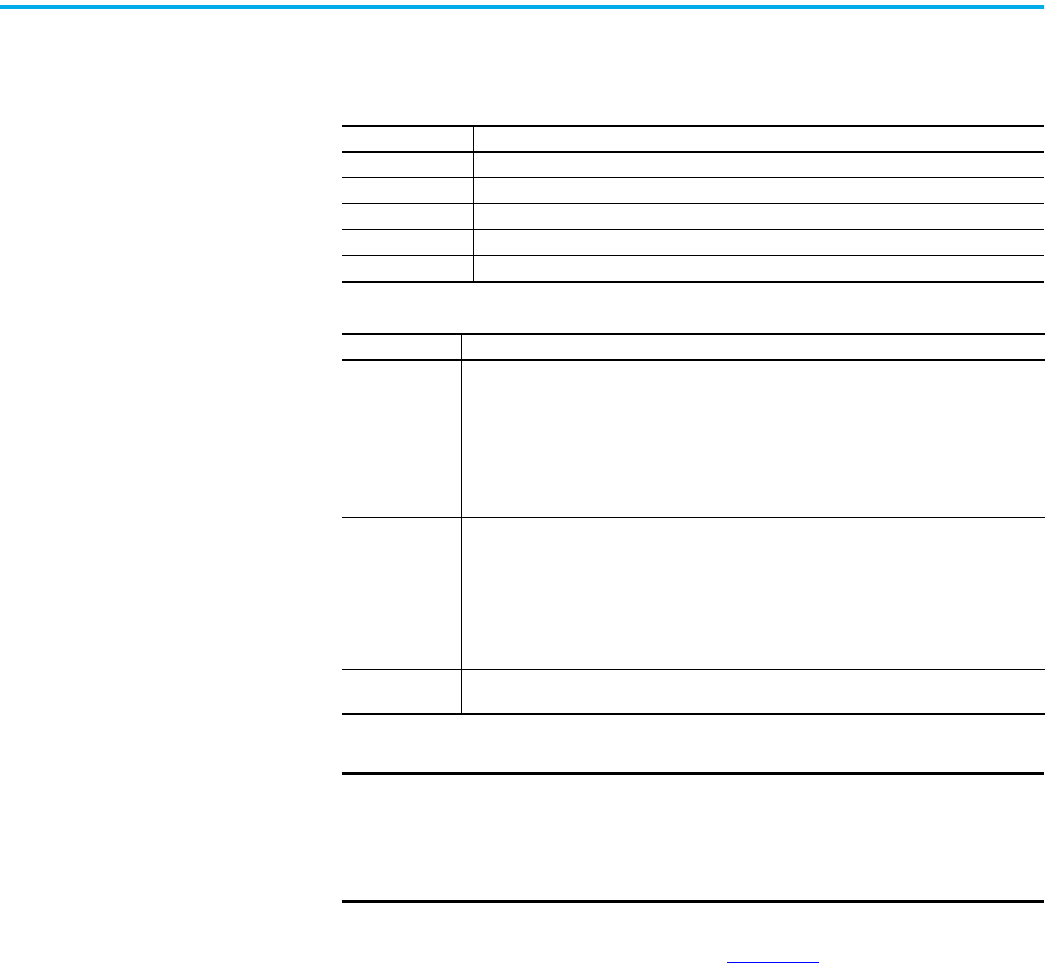
Electronic Keying Electronic Keying reduces the possibility that you use the wrong device in a control system. It
compares the device that is defined in your project to the installed device. If keying fails, a
fault occurs. These attributes are compared in the following table.
The following Electronic Keying options are available.
Carefully consider the implications of each keying option when selecting one.
For more detailed information on Electronic Keying, see Electronic Keying in Logix 5000
Control Systems Application Technique, publication LOGIX-AT001
.
Attribute Description
Vendor The device manufacturer.
Device Type The general type of the product, for example, digital I/O module.
Product Code The specific type of the product. The Product Code maps to a catalog number.
Major Revision A number that represents the functional capabilities of a device.
Minor Revision A number that represents behavior changes in the device.
Keying Option Description
Compatible
Module
Lets the installed device accept the key of the device that is defined in the project when the
installed device can emulate the defined device. With Compatible Module, you can typically
replace a device with another device that has the following characteristics:
• Same catalog number
• Same or higher Major Revision
• Minor Revision as follows:
– If the Major Revision is the same, the Minor Revision must be the same or higher.
– If the Major Revision is higher, the Minor Revision can be any number.
Disable Keying
Indicates that the keying attributes are not considered when attempting to communicate with
a device. With Disable Keying, communication can occur with a device other than the type
specified in the project.
ATTENTION: Be cautious when using Disable Keying; if used incorrectly, this option can lead to
personal injury or death, property damage, or economic loss.
We strongly recommend that you do not use Disable Keying.
If you use Disable Keying, you must take full responsibility for understanding whether the
device being used can fulfill the functional requirements of the application.
Exact Match
Indicates that all keying attributes must match to establish communication. If any attribute
does not match precisely, communication with the device does not occur.
IMPORTANT Changing Electronic Keying parameters online interrupts connections to
the device and any devices that are connected through the device.
Connections from other controllers can also be broken.
If an I/O connection to a device is interrupted, the result can be a loss of
data.

14 Rockwell Automation Publication 1756-UM004E-EN-P - June 2024
Chapter 1 ControlLogix EtherNet/IP Network Device Overview
Protected Mode The 1756-EN2F, 1756-EN2T, 1756-EN2TP, 1756-EN2TR, 1756-EN3TR, and 1756-EN4TR support
explicit protected mode.
(1)
When in this mode, the module does not allow any configuration
changes.
The only exception is for CIP Security devices such as the 1756-EN4TR. For those, if a security
policy has already been deployed to the module, then that security policy can be modified
while in explicit protected mode. If a security policy has not yet been deployed to the module,
then explicit protected mode w prevents an initial policy from being deployed.
Enabling Explicit Protected Mode
To enable the module in an “explicit protected mode state”, follow these steps.
1. Set the rotary switches to position ‘900’.
2. Power up the device, and wait for the display to scroll, “Protected Mode – Change Switch
Settings”.
3. Power down the device.
4. Set the switches for normal operation.
5. Power up the device.
6. The device is now in Explicit Protected Mode.
Operation in Explicit Protected Mode
While operating in protected mode, the module rejects any CIP explicit messages that would
change the configuration of the module. For example, you cannot change the IP address,
speed, or duplex settings when the module had Explicit Protected Mode enabled.
Disabling Explicit Protected Mode
To disable the “explicit protected mode state”, follow these steps.
1. Set the rotary switches on position ‘000’.
2. Power up the device, and wait for the display to scroll, “Unprotected Mode – Change
Switch Settings”.
3. Power down the device.
4. Set the switches for normal operation.
5. Power up the device.
6. The device is now in Unprotected Mode.
(1) For 1756-EN2F, 1756-EN2T, EN3TR, and 1756-EN2TR Versions 11.001 and later.
For 1756-EN2TP and 1756-EN4TR all versions
IMPORTANT When used in a Redundant Chassis Pair (RCP) with ControlLogix
controllers, the 1756-EN2x/1756-EN4x EtherNet/IP communication
modules have a special case for the Time Sync object, where the
PTP_Enable attribute is allowed to be set from the backplane.
This is needed to allow the controller to set the PTP enable using
unconnected messaging in the secondary (it is set via a class 1
connection in the primary controller, and in non-RCP cases).

Rockwell Automation Publication 1756-UM004E-EN-P - June 2024 15
Chapter 1 ControlLogix EtherNet/IP Network Device Overview
Protected Mode in a
Redundant Adapter Pair
The 1756-EN4TR supports explicit protected mode in a redundant adapter pair. In this mode,
the module does not allow any configuration changes.
Enabling Explicit Protected Mode in a Redundant Adapter Pair (RAP)
To enable the module in an “explicit protected mode state in RAP”, follow these steps.
1. Put your system in a qualified state.
2. Remove the secondary device from the chassis, put it in explicit mode using the
methods that are found on page 14
, and insert the module back into the chassis.
The system is qualified with the message “Explicit Protected Mode Mismatch” on the
module display.
3. Force a switchover either using AOP service or disconnect the cable.
4. Remove secondary (previous primary) device, put it in explicit mode and insert module
back.
The system has enabled explicit protected mode.
Disabling Explicit Protected Mode in a Redundant Adapter Pair
To disable the module in an “explicit protected mode state in RAP”, follow these steps.
1. Put your system in a qualified state.
2. Remove the secondary device from the chassis, put it in non-protected mode using the
methods that are found on page 14
, and insert the module back into the chassis.
The system is qualified with the message “Explicit Protected Mode Mismatch” on the
module display.
3. Force a switchover either using AOP service or disconnect the cable.
4. Remove secondary (previous primary) device, put it in non-protected mode and insert
module back.
The system has disabled explicit protected mode.
How to Determine if the Module is in Explicit Protected Mode
To determine if your module is in explicit protected mode, either view the AOP Module
information page, or create a Generic CIP message. Set the following parameters:
• Service Type: Get Single Attribute
•Class = 1
• Instance = 1
• Attribute = 13(Hex)
The Destination Element Tag must be the INT type. Bit 3 is explicit protected mode and a value
of 1 indicates that protected mode is enabled.

16 Rockwell Automation Publication 1756-UM004E-EN-P - June 2024
Chapter 1 ControlLogix EtherNet/IP Network Device Overview
Secure Digital Card The 1756-EN4TR uses a Secure Digital (SD) card to store:
• Module firmware
• Module configuration
• Fault logs
You can provide the fault logs to technical support rather than shipping then entire
module.
The SD card slot is inside the front panel of the module.
When the device is powered up, the device uses the configuration from the SD card if the
configuration does not exist in the device. When a blank SD card is inserted, or powered up,
the configuration is copied from the device to the SD card that was inserted.
If the module powers up with a configuration that does not match the configuration on the
already inserted SD card, the configuration on the SD card is used and copied to the module.
If the module is already powered, and an SD card is inserted, a warning message is displayed.
To change these results, do one of two things. One option is to do an out of box reset on the
module, if you want to use the configuration on the SD card. A second option is to modify one
of the configuration settings on the device, if you want to use the configuration on the device.
IMPORTANT The 1756-EN4TR does not save the CIP Security configuration
information to the SD card. On power-up, the CIP Security setting
returns to the module default setting.
To see other potential error messages, see Table 12 on page 60.
SD Card inside front panel.

Rockwell Automation Publication 1756-UM004E-EN-P - June 2024 17
Chapter 1 ControlLogix EtherNet/IP Network Device Overview
The 1756-EN4TR supports the use of a 1784-SD1 (1 GB) and 1784-SD2 (2 GB) card. You can use
third-party SD cards with the device. You can use SD cards with as much as 32 GB of memory.
If you use an SD card other than those cards that are available from Rockwell Automation,
unexpected results can occur. For example, you can experience data corruption or data loss.
SD cards that are not provided by Rockwell Automation can have different industrial,
environmental, and certification ratings as those cards that are available from Rockwell
Automation. These cards can have difficulty with survival in the same industrial environments
as the industrially rated versions available from Rockwell Automation.
Disable Secure Digital Card
To disable the SD card, see Disable/Enable the SD Card on page 48.
CIP Security CIP Security™ is a standard, open communication mechanism that is defined by the Open
DeviceNet® Vendors’ Association (ODVA) that helps to provide a secure data transport across
an EtherNet/IP™ network. It lets CIP-connected devices authenticate each other before
transmitting and receiving data.
CIP Security uses the following security properties to help devices protect themselves from
malicious communication:
• Device Identity and Authentication
• Data Integrity and Authentication
• Data Confidentiality
Rockwell Automation uses the following products to implement CIP Security:
• FactoryTalk Services Platform, version 6.11 or later, with the following components
enabled:
- FactoryTalk Policy Manager
- FactoryTalk System Services
• FactoryTalk Linx, version 6.11 or later
• Studio 5000® Design Environment, version 31.00.00 or later
• CIP Security-enabled Rockwell Automation products, for example, the product
described in this publication
For more information on CIP Security, including which products support CIP Security, see the
CIP Security with Rockwell Automation Products Application Technique, publication
SECURE-AT001
.
IMPORTANT If an SD card with a valid configuration is inserted into a 1756-EN4TR
module that does not match, an error is displayed on the status display
on the front of the module warning of this mis-configuration. If the SD
card is intended to be used in the 1756-EN4TR module it must be cleared
by external means and reinserted. If this is not done before the next
power cycle of the 1756-EN4TR with the non-matching configuration, this
configuration is copied to the 1756-EN4TR with all settings including the
IP address from the original module. This can possibly cause an IP
address conflict.
IMPORTANT Rockwell Automation does not test the use of third-party SD cards with
the device.

18 Rockwell Automation Publication 1756-UM004E-EN-P - June 2024
Chapter 1 ControlLogix EtherNet/IP Network Device Overview
Syslog Event Logging
The 1756-EN4TR module supports syslog event logging. Do not use FactoryTalk AssetCentre for
logging if you want to use a syslog collector.
Choose a syslog collector that supports the following:
• RFC-5424 syslog protocol
• Ability to receive messages from the 1756-EN4TR module
To set the IP address of the syslog collector, use FactoryTalk Policy Manager software.
For more information, see:
• CIP Security with Rockwell Automation Products Application Technique, publication
SECURE-AT001
.
• Logix 5000 Controller and I/O Fault Codes and Syslog Messages, publication 1756-RD001
.
IMPORTANT Redundant Chassis Pair
1756-EN4TR modules with firmware revision 4.001 support CIP Security
when used in a redundant chassis pair with ControlLogix 5580
controllers that have firmware revision 34.011 or later. This supports
program upload/download/monitor/HMI (not I/O).
• The 1756-EN4TR pair must be configured for non-IP address swapping.
• The 1756-EN4TR pair cannot be configured for redundant adapter mode
while used in a redundant chassis pair with ControlLogix 5580
controllers.
• The 1756-EN4TR pair that is configured for CIP security cannot be used to
communicate with remote I/O, because I/O in ControlLogix redundancy
requires multi-cast. A second 1756-EN4TR pair is required for I/O.
Redundant Adapter Mode
CIP Security is not yet supported when the 1756-EN4TR is in redundant
adapter mode for remote I/O.
If a 1756-EN4TR is installed and using CIP Security, and it is reconfigured
to be part of a redundant adapter pair for remote I/O, the module loses
its CIP Security configuration. When this occurs, the I/O chassis will lose
communication with the controller. At this point, the CIP Security policy
must be redeployed.
(1)
(1) CIP Security is not supported in redundant adapters. See Chapter 3 on page 25.
IMPORTANT The 1756-EN4TR module must be connected to the same network as the
syslog collector.

Rockwell Automation Publication 1756-UM004E-EN-P - June 2024 19
Chapter 1 ControlLogix EtherNet/IP Network Device Overview
Parallel Redundancy
Protocol
Parallel Redundancy Protocol (PRP) is defined in international standard IEC 62439-3 and
provides high-availability in Ethernet networks. PRP technology creates seamless redundancy
by sending duplicate frames to two independent network infrastructures, which are known as
LAN A and LAN B.
A PRP network includes the following components.
For more information about PRP, see the EtherNet/IP Parallel Redundancy Protocol Application
Technique, publication ENET-AT006
.
Device Level Ring (DLR) Device Level Ring (DLR) is an EtherNet/IP protocol that is defined by the Open DeviceNet®
Vendors’ Association (ODVA). DLR provides a means to detect, manage, and recover from single
faults in a ring-based network.
A DLR network includes the following types of ring nodes.
Depending on their firmware capabilities, both devices and switches can operate as
supervisors or ring nodes on a DLR network. Only switches can operate as redundant
gateways.
For more information about DLR, see the EtherNet/IP Device Level Ring Application Technique,
publication ENET-AT007
.
Component Description
LAN A and LAN B Redundant, active Ethernet networks that operate in parallel.
Double attached node (DAN) An end device with PRP technology that connects to both LAN A and LAN B.
Single attached node (SAN)
An end device without PRP technology that connects to either LAN A or LAN B.
A SAN does not have PRP redundancy.
Redundancy box (RedBox)
A switch with PRP technology that connects devices without PRP technology to
both LAN A and LAN B.
Virtual double attached node
(VDAN)
An end device without PRP technology that connects to both LAN A and LAN B
through a RedBox.
A VDAN has PRP redundancy and appears to other nodes in the network as a DAN.
Infrastructure switch A switch that connects to either LAN A or LAN B and is not configured as a RedBox.
Table 5 -
Node Description
Ring supervisor
A ring supervisor provides these functions:
Manages traffic on the DLR network
Collects diagnostic information for the network
A DLR network requires at least one node to be configured as ring supervisor.
By default, the supervisor function is disabled on supervisor-capable devices.
Ring participants
Ring participants provide these functions:
Process data that is transmitted over the network.
Pass on the data to the next node on the network.
Report fault locations to the active ring supervisor.
When a fault occurs on the DLR network, ring participants reconfigure themselves and
relearn the network topology.
Redundant gateways
(optional)
Redundant gateways are multiple switches that are connected to one DLR network and
also connected together through the rest of the network.
Redundant gateways provide DLR network resiliency to the rest of the network.

20 Rockwell Automation Publication 1756-UM004E-EN-P - June 2024
Chapter 1 ControlLogix EtherNet/IP Network Device Overview
Notes:

Rockwell Automation Publication 1756-UM004E-EN-P - June 2024 21
Chapter 2
Connect to the EtherNet/IP Network
EtherNet/IP™ networks are communication networks that offer a comprehensive suite of
messages and services for many automation applications.
The following are examples of applications that use EtherNet/IP networks:
•Real-Time Control
• Time Synchronization
•Motion
This open network standard uses commonly available Ethernet communication products to
support real-time I/O messaging, information exchange, and general messaging.
EtherNet/IP networks also support CIP Safety™, which makes the simultaneous transmission
of safety and standard control data and diagnostics information over a common network
possible.
Set the IP Address The following conditions are required to set the IP address.
Requirements
To set the IP address, have the following:
• EtherNet/IP or USB drivers that are installed on the programming workstation
• MAC ID from the device, which is on the label on the side of the device
• Recommended IP address for the device
Topic Page
Set the IP Address 21
Set the IP Address with Rotary Switches 22
Other Methods to Set the Address 23
Reset the Module to Factory Default Value 23
Redundant Adapter Considerations Setting the IP Address 24

22 Rockwell Automation Publication 1756-UM004E-EN-P - June 2024
Chapter 2 Connect to the EtherNet/IP Network
Set the IP Address with
Rotary Switches
This graphic shows the rotary switches on a 1756 EtherNet/IP communication module. The
three rotary switches at the bottom of the module, labeled X, Y, and Z, can be used for setting
the IP address. If the rotary switches are not set to a valid number, the module attempts to use
the BOOTP/DHCP server to set the IP address.
At power-up, the module reads the rotary switches to determine if they are set to a valid
number for the last portion of the IP address. Valid numbers range from 001…254.
If the settings are a valid number, these conditions result:
• IP address = 192.168.1.xxx (where xxx represents the switch settings)
• Subnet mask = 255.255.255.0
• Gateway address = 192.168.1.1
• The module does not have a host name that is assigned to it, nor does it use any
Domain Name System
We recommend that you set the rotary switches to a valid number before installing the
module.
Some modules now provide a gateway address of 0.0.0.0 when the network
address is set with rotary switches.
IMPORTANT For more information on how to use the BOOTP/DHCP server to set the IP
address, see EtherNet/IP Network Configuration Manual,
publication ENET-UM006
32794 M

Rockwell Automation Publication 1756-UM004E-EN-P - June 2024 23
Chapter 2 Connect to the EtherNet/IP Network
1756-EN4TR Mode Rotary Switch
The rotary switch in the upper left corner of the module is reserved for DLR, PRP, and
redundancy features.
• For modules built with firmware revision 4.001 or later, the default position of the
switch is 0.
• For modules built with firmware revision 3.002 and earlier, the default position of the
switch set to 9 for DLR, linear, or star topologies.
• The switch must be set to 7 for a redundant adapter with DLR or star topologies.
• The switch must be set to 6 for a redundant adapter with PRP.
• Set the switch to the appropriate mode according to Table 6
.
If the switch is in a position that is not implemented, the module displays the message
“Unsupported mode. Change rotary switch setting” on the status display. The module
does not respond on any port until the mode switch is set to the correct position and is
power-cycled.
Table 6
shows the capabilities of the mode rotary switch.
Other Methods to Set the
Address
The modules support the following additional methods to change the IP address:
•RSLinx® Classic software
• EtherNet/IP Commissioning Tool
• FactoryTalk® Linx Network Browser software
• Studio 5000 Logix Designer® Application
• Using Secure Digital Card (1756-EN4TR only)
• For more information on how to use these methods, see EtherNet/IP Network
Configuration Manual, publication ENET-UM006
.
Reset the Module to Factory
Default Value
You can reset the configuration of the module to its factory default value with the following
method.
If the module has rotary switches, set the switches to 888 and cycle power.
ATTENTION: If the mode rotary switch is set to 9 (DLR), and you insert
the module into a PRP network, it can disable the network because it
will directly connect PRP LAN A and PRP LAN B.
Table 6 - Mode Rotary Switch Capabilities
Switch Position Capability
9 DLR or Single-port
8 PRP or Single-port
7 Redundant Adapter and DLR or single-port topologies
6 Redundant Adapter and PRP or single-port topologies
IMPORTANT If you use a redundant adapter pair, the mode rotary switches of both
modules in the redundant adapter pair must be set to the same value.

24 Rockwell Automation Publication 1756-UM004E-EN-P - June 2024
Chapter 2 Connect to the EtherNet/IP Network
Redundant Adapter
Considerations Setting the
IP Address
The following are considerations when using two 1756-EN4TR modules as a Redundant Adapter
Pair.
• DHCP is not supported in Redundant Adapter Mode.
• Default Class C addresses like 192.168.1.x can be set using rotary switches on the
module in any mode.
• IP address assignments other than default Class C can only be set in non-redundant
adapter mode, where the switch is set to 8 or 9.
• Both 1756-EN4TR modules must be set to the same IP address before switching to
Redundant Adapter Mode, where the switch is set to 6 or 7.
• You must reserve an IP+1 address that is taken automatically by the secondary.
For example, if the primary address is 192.168.1.1, the address 192.168.1.2 must be
reserved.
To set the IP address for redundant adapters use the following steps.
1. Insert one module into the chassis in the standard mode (rotary mode switch set to 8 or
9).
2. Set the IP address on the module.
3. Remove the module from the chassis.
4. Insert a second module into the chassis.
5. Set the same IP address on the second module as you set on the first module.
6. Set the rotary mode switches to 6 or 7 on both modules to put the modules in redundant
adapter mode, and put the modules in slots 0 and 1.

Rockwell Automation Publication 1756-UM004E-EN-P - June 2024 25
Chapter 3
Connect Redundant EtherNet/IP Adapters
Redundant 1756-EN4TR adapters can be used for added resiliency at the adapter level. One
adapter acts as the primary and controls the I/O, while the other adapter acts as a secondary
and can take over as the primary if needed. Redundant Adapter functionality is available
starting in revision 3.001 firmware.
Redundant Design
Considerations
There are some details and rules to consider with redundant design considerations in the
following list.
• Do not exceed 80% of the maximum allowed packet rate capacity
(max: 50,000 pps).
• Only I/O modules are supported in the redundant adapter chassis. The redundant
chassis does not support the following.
- motion modules
- communication modules such as DHRIO and DeviceNet®
- controllers
• Redundant adapters must reside in slots 0 and 1 only.
• The fourth rotary switch on the redundant 1756-EN4TR adapter must be set to number 7
for a redundant adapter with DLR, or 6 for a redundant adapter with PRP. Note that PRP
is available starting with firmware revision 4.001.
Topic Page
Redundant Design Considerations 25
Redundant System Components 26
Redundant Switchovers 26
Configure a 1756-EN4TR Redundant Adapter Pair 28
Redundant Architecture 33
Redundant Architecture Network Considerations 35
PRP Architecture with RedBox Switches 37
PRP Architecture without RedBox Switches 38
ATTENTION: For redundant adapter functionality, two 1756-EN4TR adapters
must have configurations that match, including IP addresses and rotary
switches, in both slot 0 and 1.
If you are using one 1756-EN4TR adapter, it functions as one adapter.
If a redundant adapter is in slot 0 or slot 1, then both of those slots must
contain a redundant adapter. No other types of modules can be part of the
pair.

26 Rockwell Automation Publication 1756-UM004E-EN-P - June 2024
Chapter 3 Connect Redundant EtherNet/IP Adapters
Redundant System
Components
The following features are supported with the 1756-EN4TR redundant adapter pair in firmware
revision 4.001 or later:
•PRP
The following features are not currently supported with the 1756-EN4TR redundant adapter
pair.
• CIP Safety™ modules
•CIP Security™
Redundant adapters can be used with redundant controllers or one controller.
For more information on redundancy, see:
• ControlLogix® 5570 Redundancy User Manual, publication 1756-UM535
• ControlLogix 5580 Redundant Controller User Manual,
publication 1756-UM015
Redundant Switchovers During redundant adapter operation, if certain conditions occur to the primary adapter,
control is switched to the secondary adapter. These conditions cause a switchover:
• Major fault/assert on the adapter
• Failure of the adapter
• Removal of the adapter
• A program-prompted command to switchover
• An AOP-prompted command to switchover
• The adapter loses both Ethernet links
Switchover Considerations
Each 1756-EN4TR adapter uses one IP address as the primary IP address for all communication
on the EtherNet/IP™ network. The redundant adapter pair consists of one active and one
stand-by adapter.
The two adapters negotiate which is the primary, depending on the status of the system. If the
primary adapter is unable to perform its role, for example, if a fault occurs in the primary
adapter, then the secondary adapter becomes the new primary, assuming the IP address of
the first primary adapter and taking over the role of communication. The primary adapter is
the only adapter of the pair that produces data on the EtherNet/IP network.
On power-up, the primary is chosen from a pair of devices. The secondary adapter uses the
primary IP address +1. For example, if the primary adapter has an IP address of ‘N’, then the
secondary adapter has an IP address of ‘N+1’.
The primary adapter is always active and is responsible for monitoring all inputs and outputs,
monitoring diagnostics in the system, and reading and writing data to and from I/O
simultaneously. The secondary adapter is waiting to take over communication, if the primary
switches over.
If there is a switchover, the IP address swapping between the primary adapter and the
secondary adapter takes no longer than 50 ms from the time of the initiating fault. The
secondary adapter is the new primary and handles all communication. Depending on the RPIs
configured, the observed switchover time can appear longer. Transmission time that is
imposed by network infrastructure has to be considered when calculating overall switchover
time. No connection drops occur during this switchover process.
This IP address swap is transparent to the user. You can detect which adapter the primary
adapter is by examining the four character display indicator near the top of each adapter. On
the primary adapter, the network status indicator is steady green. On the secondary adapter,
the network status indicator flashes green.

Rockwell Automation Publication 1756-UM004E-EN-P - June 2024 27
Chapter 3 Connect Redundant EtherNet/IP Adapters
Once a swap occurs, the ‘new’ primary adapter remains the primary unless there is a reason to
swap over again. When the previous primary adapter is reinserted or reconnected, both
adapters start the qualification process again with the adapter that was reconnected
becoming the new qualified secondary.
Status Display Codes
Table 7 shows the different Redundant Adapter status codes that can appear on the adapter.
Adapter Qualification
In a Redundant Adapter configuration, one adapter takes the Primary role and a second
adapter becomes the Qualified Secondary ready to take I/O control when the primary becomes
disqualified.
To complete the qualification process the following conditions must be met. The modules
must:
• have the same firmware revision.
• reside in slots 0 and 1 of the same chassis.
• be initially set to the same IP address.
• have at least one Ethernet port link active.
• be connected to the same Ethernet network.
Table 7 - Primary and Secondary Operation Modes
Status Code Description
PwrUp Power Up/ Unknown
DS Disqualified secondary
QS Qualified secondary
PwQs Primary with qualified secondary partner
PwDS Primary with disqualified secondary
PwNS Primary with no secondary
DSwP Disqualified secondary with primary

28 Rockwell Automation Publication 1756-UM004E-EN-P - June 2024
Chapter 3 Connect Redundant EtherNet/IP Adapters
Configure a 1756-EN4TR
Redundant Adapter Pair
To configure a 1756-EN4TR redundant adapter pair, use the following steps.
1. To set the IP address, see page 24
.
2. Make sure you are using the Studio 5000 Logix Designer® application in offline mode.
3. In the I/O configuration tree, add the 1756-EN4TR in slot 0.
4. Name your module and enter the IP address.
5. Click change under the module definition pane, and select "Yes" for redundancy.
6. If you have one of the following modules in your chassis, Select Time Sync and Motion.
- 1756-IB16IF
-756-OB16IEF
-1756-OB16IEFS
When a chassis is configured for a 1756-EN4TR redundant adapter pair and the I/O
chassis contains any of the preceding modules, then the 1756-EN4TR modules must
be configured as Time Sync and Motion or unexpected connection drops can occur.
IMPORTANT Do not put any devices in slot 1 in the I/O configuration tree.

Rockwell Automation Publication 1756-UM004E-EN-P - June 2024 29
Chapter 3 Connect Redundant EtherNet/IP Adapters
7. Power the adapters, and the synchronization process starts. Once synchronization has
completed, one adapter reports as PwQS and the other adapter reports as QS. This
status displays on the adapter.
The adapter that reports as QS has an IP address that was incremented by one, which
was incremented by the firmware in the module.
8. Go online with the project and click Download.
9. Examine the AOP screens by right-clicking on the module and select Properties.
You can now see options in your configuration tree for Module Info Primary, Module Info
Secondary, and Redundancy.
The image below shows the Module Info Primary Tab.

30 Rockwell Automation Publication 1756-UM004E-EN-P - June 2024
Chapter 3 Connect Redundant EtherNet/IP Adapters
10. Under the Redundancy tab, click Qualify Secondary.
11. Click the Module Info Secondary page and examine the information.
In the Status table, the Configured section says “No” if it is not qualified.

Rockwell Automation Publication 1756-UM004E-EN-P - June 2024 31
Chapter 3 Connect Redundant EtherNet/IP Adapters
12. To verify that the redundancy feature created a redundant adapter system, click the
General tab.
You should see the properties for the module defined with both Slot 0 and Slot 1.
If the primary module was in slot 1 and a switchover occurred, you can see a change in
the serial number of the module to match the module in slot 1.

32 Rockwell Automation Publication 1756-UM004E-EN-P - June 2024
Chapter 3 Connect Redundant EtherNet/IP Adapters
13. To confirm that a switchover occurred and there is no longer a secondary, on the
redundancy page, click refresh. You should see “No Secondary” appear.
In the following figure, there is an example of an I/O module in slot 1. Even with a 1756-EN4TR in
slot 0, with any other module apart from a second 1756-EN4TR in slot 1 (in this example it is the
1756-IF8) you cannot enable redundancy. On the module redundancy page, any attempt that is
made to change the redundant function to "yes" results in the following error.
If you try to make a redundancy system starting in any other slot in the chassis other than slot
0, the redundancy option will not be available on the module definition configuration screen.
The redundant adapter must be present in slot 0.

Rockwell Automation Publication 1756-UM004E-EN-P - June 2024 33
Chapter 3 Connect Redundant EtherNet/IP Adapters
Redundant Architecture The following figures show DLR and Star Topology with the 1756-EN4TR module. DLR provides
higher resiliency than a single star. Linear topologies are not recommended because any
break or firmware updating of devices in the line causes loss of communications to
downstream devices.
Figure 2 - Redundant 1756-EN4TR Adapters in DLR Topology
1756-EN2TR
(can also be a 1756-EN4TR)
1756-EN4TR pair
Configure all DLR devices on the ring to be at the same speed on all links as
defined in the Deploying Device Level Ring within a Converged Plantwide Ethernet
Architecture design and implementation guide, ENET-TD015.

34 Rockwell Automation Publication 1756-UM004E-EN-P - June 2024
Chapter 3 Connect Redundant EtherNet/IP Adapters
Redundant adapters can be used in a star configuration, as shown in Figure 3. However, the
switch at the center of the star is a single point of failure. DLR provides for higher resiliency.
Figure 3 - Redundant 1756-EN4TR Adapters in Star Topology with a Single Switch
R
1756-EN4TR pair
1756-EN4TR or
1756-EN2T

Rockwell Automation Publication 1756-UM004E-EN-P - June 2024 35
Chapter 3 Connect Redundant EtherNet/IP Adapters
Redundant Architecture
Network Considerations
In a star topology with a single switch, if a link is broken between the switch and the primary
redundant adapter, a switchover occurs. With multiple switches, for example as shown in
Figure 4
, if a link is broken between two switches, a switchover does not occur because the
link to the redundant adapter is still in place.
Figure 4 - Invalid Topology: Network Break Does not Cause Switchover
R
R
R
Primary
Secondary

36 Rockwell Automation Publication 1756-UM004E-EN-P - June 2024
Chapter 3 Connect Redundant EtherNet/IP Adapters
The Primary Adapter does not detect data connection loss on non-directly connected links. For
example in Figure 5, the secondary adapter disqualifies because it cannot detect the primary
adapter.
This action occurs even though the secondary adapter still has a healthy path to the primary
controller.
Similarly, the secondary controller in the redundant controller pair disqualifies because it
cannot detect the primary.
Figure 5 - Invalid Topology: Network Break Results in Loss of Control
R
R
Primary
Primary
Secondary
Secondary

Rockwell Automation Publication 1756-UM004E-EN-P - June 2024 37
Chapter 3 Connect Redundant EtherNet/IP Adapters
PRP Architecture with
RedBox Switches
PRP, including RedBox switches, must be properly designed, built, and configured based on
CPwE guidelines. For more information, see the Deploying Parallel Redundancy Protocol within
a Converged Plantwide Ethernet Architecture Technical Data.
With Logix Designer application version 33 and 1756-EN4TR firmware 3.001, you can use
1756-EN4TR redundant adapters in the I/O chassis with PRP as shown in Figure 6
.
• The 1756-EN4TR firmware 3.001 does not natively support PRP, which is why the 1756-
EN4TRs must be connected to RedBox switches.
• The 1756-EN4TR firmware 3.001 does not support the 1756-EN4TR being placed in the
redundant chassis pair, so the 1756-EN2TP is the module being used to connect the
redundant chassis pair to the PRP LAN A and LAN B.
Figure 6 - PRP Network with RedBox Switches and Redundant Adapters
LAN A
LAN B
RedBox 1
RedBox 2

38 Rockwell Automation Publication 1756-UM004E-EN-P - June 2024
Chapter 3 Connect Redundant EtherNet/IP Adapters
PRP Architecture without
RedBox Switches
PRP must be properly designed, built, and configured based on CPwE guidelines. For more
information, see the Deploying Parallel Redundancy Protocol within a Converged Plantwide
Ethernet Architecture Technical Data.
With Studio 5000 Logix Designer application version 34 and later, and
1756-EN4TR firmware 4.001 and later, the 1756-EN4TR can be used in the ControlLogix® 5580
redundant chassis pair.
• The 1756-EN4TR cannot be placed in a ControlLogix 5570 redundant chassis pair.
• Redundant 1756-EN4TR adapters can also be placed in the remote I/O chassis, as they
could starting with firmware 3.001.
• RedBox switches are no longer needed because the 1756-EN4TR natively supports PRP
with firmware 4.001 and later.
Follow these guidelines:
• Use EtherNet/IP modules that support the redundant adapter feature.
• Connect the redundant adapters in the I/O chassis to LAN A and LAN B.
Figure 7 - PRP Network with Redundant Adapters
LAN A
LAN B
1756-EN4TR Redundant Adapter Pair
1756-EN4TR as a single adapter
1756-EN4TR
1756-EN4TR

Rockwell Automation Publication 1756-UM004E-EN-P - June 2024 39
Chapter 4
Security Options
For enhanced security, you can disable specific functionalities on an Ethernet communication
module as desired.
MSG Instruction You can use a CIP™ Generic MSG to disable many of the functionalities on a module. This CIP
Generic MSG originates in the controller and is sent to the communication module receiving
the change.
Configure the MSG Communication Path
While the Configuration tab on the Message Configuration dialog requires specific information
to disable or enable a specific feature, the method for configuring the message
communication path is the same for all features.
Communication goes through the backplane and Ethernet ports. When you configure the
communication path, the values in the path specify backplane or Ethernet port:
•1 - Backplane
•2 - Ethernet port
Module In The Local Chassis
To disable or enable functionality in a module in the Local Chassis, the path is:
1, slot number of local module.
The path below is 1,1 denoting that the message originating in the controller is going to the
backplane (the first 1) over to slot 1 (the second 1), which is the location of the local_EN2TR
module that is receiving the change.
Topic Page
MSG Instruction 39
Disable/Enable an Ethernet Port 41
Disable the CIP Security Ports 44
Disable/Enable LLDP 46
Disable the USB Port 47
Disable/Enable the SD Card 48
Disable/Enable the 4-character Status Display 50
Disable/Enable the Webpages 52
Disable/Enable Simple Network Management Protocol (SNMP) 54
Disable the Socket Object 56
Disable the Email Object 56

40 Rockwell Automation Publication 1756-UM004E-EN-P - June 2024
Chapter 4 Security Options
Remote Module Connected Through A Controller Ethernet Port
To disable or enable functionality in a module in a remote chassis that is connected through
the front port of a controller, the path is:
2 (denoting out the Ethernet port), IP address of the remote module that is receiving the
change.
Remote Module Connected to Controller Through a Module in the Local Chassis
To disable or enable functionality in a module in a remote chassis that is connected through
an Ethernet module in the local chassis, the path is:
1 (denoting from the controller to the backplane), slot number of local communication
module, 2 (denoting out the Ethernet port of the communication module), IP address of
remote module that is receiving the change.

Rockwell Automation Publication 1756-UM004E-EN-P - June 2024 41
Chapter 4 Security Options
Disable/Enable an Ethernet
Port
You can disable or enable an Ethernet port three ways:
• Disable/Enable an Ethernet Port with FactoryTalk Linx Network Browser
on page 41
• Disable/Enable an Ethernet Port on the Port Configuration Tab on page 42
• Disable an Ethernet Port with a MSG Instruction on page 43
Ethernet ports return to the default setting after the module is reset to factory defaults. You
must reconfigure the settings to disable an Ethernet port after the port returns to its default
settings.
Disable/Enable an Ethernet Port with FactoryTalk Linx Network
Browser
You can disable or enable an Ethernet port with FactoryTalk® Linx software, version 6.30.00 or
later.
1. On the Factory Talk Linx Network Browser, select the Ethernet module, and click
Configure Device.
2. On the Port Configuration category:
• To disable an Ethernet port, clear the Enabled checkbox.
• To enable an Ethernet port, select the Enabled checkbox.
3. Click Apply.
4. Click Yes on the confirmation messages that appear. The change takes effect
immediately.
5. Click Refresh.
Applies to these modules:
1756-EN2x
1756-EN4x
IMPORTANT Remember the following:
• Once a port is disabled, you lose any connection that is established
through the controller Ethernet port.
• You cannot disable Ethernet ports if the controller keyswitch is in Run
mode or if the FactoryTalk® Security settings deny this editing option.

42 Rockwell Automation Publication 1756-UM004E-EN-P - June 2024
Chapter 4 Security Options
Disable/Enable an Ethernet Port on the Port Configuration Tab
You can disable or enable an Ethernet port with the Studio 5000 Logix Designer® application,
version 28.00.00 or later.
This method retains the setting in the project every time you download the project to the
controller.
1. Go online with the controller.
2. To open the module properties, double-click the Ethernet module.
3. On the Port Configuration category:
• To disable an Ethernet port, clear the Enable checkbox.
• To enable an Ethernet port, select the Enable checkbox.
4. On the Port Configuration tab, click Set.
5. On the dialog box, click Yes. The change takes effect immediately.
6. On the Port Configuration category, click OK.
IMPORTANT To disable an Ethernet port, the Link Status for one port must be Active.
Rockwell Automation Publication 1756-UM004E-EN-P - June 2024 43
Chapter 4 Security Options
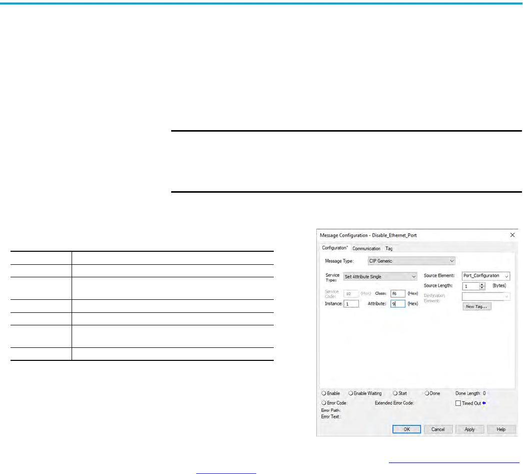
Disable an Ethernet Port with a MSG Instruction
You can disable an Ethernet port with the Studio 5000 Logix Designer application, version
28.00.00 or later. You cannot use this MSG instruction to disable the Ethernet port on a
different controller.
1. Add a MSG instruction to your program.
This message only has to execute once, it does not need to execute with every program
scan.
2. Configure the Configuration tab on the Message Configuration dialog box as follows:
3. On the Communication tab, configure the Path. See Configure the MSG Communication
Path on page 39.
4. Before you enable the MSG instruction, make sure that the Source Element tag value is
2.
To re-enable the port, complete the steps that are described in this section. Before you
enable the MSG instructions, however, make sure that the Source Element tag value is 1.
IMPORTANT • These values are stored to NVS memory in such a way that the MSG
instruction is not required to execute each time the controller powers up.
• You cannot add a MSG instruction to your program if the controller
keyswitch is in Run mode, or if the FactoryTalk Security settings deny
this editing option.
Table 1 - Disable an Ethernet Port
Message Type: CIP Generic
Service Type: Set Attribute Single
Instance:
1 for single port modules
1 for Port 1, 2 for Port 2 on dual-port modules
Class: f6
Attribute: 9
Source Element:
Controller tag of SINT data type.
In this example, the controller tag is named Port_Configuration.
Source Length: 1

44 Rockwell Automation Publication 1756-UM004E-EN-P - June 2024
Chapter 4 Security Options
Disable the CIP Security
Ports
There are two ways to disable CIP Security™ ports:
• Use the Disable CIP Security checkbox in FactoryTalk Linx software, version 6.30.00 or
later. See Disable the CIP Security Ports with FactoryTalk Linx Network Browser
on
page 44
• Disable the CIP Security Ports with a MSG Instruction on page 45
Disable the CIP Security Ports with FactoryTalk Linx Network
Browser
You can disable the CIP Security ports with FactoryTalk Linx Network Browser, version 6.30.00
or later.
1. On the Factory Talk Linx Network Browser, select 1756-EN4TR, and click Configure
Device.
2. Click CIP Security.
3. Select the Disable CIP Security (Port 2221) checkbox.
4. Click Apply.
5. Click Yes on the confirmation messages that appear.
Applies to these modules:
1756-EN4x
IMPORTANT These procedures disable the CIP Security ports. To re-enable the ports,
you must use the rotary switches to return the controller to a factory
default state. See Reset the Module to Factory Default Value
on page 23.

Rockwell Automation Publication 1756-UM004E-EN-P - June 2024 45
Chapter 4 Security Options
Disable the CIP Security Ports with a MSG Instruction
With the Studio 5000 Logix Designer application, version 32.00.00 or later, use a CIP Generic
MSG to execute this option. The message only has to execute once, it does not need to execute
with every program scan.
1. Create a controller tag of SINT[9] data type.
In this example, the controller tag is named CIPSEC_DISABLE and must match the
following graphic.
Before you enable the MSG instruction, consider the following:
- The element CIPSEC_DISABLE[4] is responsible for disabling UDP port 2221 and
EtherNet/IP™ over DTLS, transport class 0/1.
- The element CIPSEC_DISABLE[8] is responsible for disabling TCP port 2221 and
EtherNet/IP over TLS, UCMM, and transport class 3.
- To disable the controller CIP Security™ ports, the elements CIPSEC_DISABLE[4] and
CIPSEC_DISABLE[8] in the SINT array for the Source Element CIPSEC_DISABLE must
be 0.
2. Add a MSG instruction to your program.
3. Configure the Configuration tab on the Message Configuration dialog box as follows:
4. On the Communication tab, configure the Path. See Configure the MSG Communication
Path on page 39.
5. Cycle power on the controller for the configuration to take effect.
IMPORTANT You cannot add a MSG instruction to your program if the
controller keyswitch is in RUN mode, or if the FactoryTalk
Security settings deny this editing option.
Table 2 - Disable the CIP Security Ports
Message Type: CIP Generic
Service Type: Custom
Service Code: 4c
Instance: 1
Class: f5
Attribute: 0
Source Element:
Controller tag of SINT[9] data type. This is the controller tag
that you created in step 1.
Source Length: 9

46 Rockwell Automation Publication 1756-UM004E-EN-P - June 2024
Chapter 4 Security Options
Disable/Enable LLDP Link Layer Discovery Protocol (LLDP) is used by network devices to advertise their identity,
capabilities, and neighbors on a local area network.
You can disable or enable LLDP with FactoryTalk Linx Network Browser, version 6.30.00 or
later.
1. On the Factory Talk Linx Network Browser, select the module, and click Configure
Device.
2. On the LLDP category:
• To disable LLDP, clear the Enabled checkbox.
• To enable LLDP, select the Enabled checkbox..
3. Click Apply.
4. Click Yes on the confirmation messages that appear.
Applies to these modules:
1756-EN2x
1756-EN4x

Rockwell Automation Publication 1756-UM004E-EN-P - June 2024 47
Chapter 4 Security Options
Disable the USB Port With the Studio 5000 Logix Designer application, version 32.00.00 or later, use a CIP Generic
MSG to execute this option.
1. Add a MSG instruction to your program.
This message only has to execute once, it does not need to execute with every program
scan.
2. Configure the Configuration tab on the Message Configuration dialog box as follows:
3. On the Communication tab, configure the Path. See Configure the MSG Communication
Path on page 39.
Applies to these modules:
1756-EN2x
1756-EN4x
IMPORTANT • These values are stored to NVS memory in such a way that the MSG
instruction is not required to execute each time the controller powers up.
• You cannot add a MSG instruction to your program if the controller
keyswitch is in Run mode, or if the FactoryTalk Security settings deny
this editing option.
Table 3 - Disable the USB Port
Message Type: CIP Generic
Service Type: Set Attribute Single
Instance: 1
Class: 33a
Attribute: 4
Source Element:
Controller tag of SINT data type.
In this example, the Source Element is named Port_Configuration.
Source Length: 1

48 Rockwell Automation Publication 1756-UM004E-EN-P - June 2024
Chapter 4 Security Options
Disable/Enable the SD Card You can disable or enable the SD card two ways:
• Disable/Enable the SD Card on the Module Properties Dialog
on page 48
• Disable/Enable the SD Card with a MSG Instruction on page 49
Disable/Enable the SD Card on the Module Properties Dialog
This method retains the setting in the project every time you download the project to the
controller.
On the SD Card category in the module properties dialog:
• To disable the SD card, clear the Enable SD Card checkbox and click Set.
• To enable the SD card, select the Enable SD Card checkbox and click Set.
Applies to these modules:
1756-EN4x
IMPORTANT Remember the following:
• Once an SD Slot is disabled, you lose all and any ability to communicate
to an SD Card inserted into the slot. This includes any diagnostic
information.
• To re-enable the SD card again:
- Use the rotary switches to rest the module to factory defaults.
- Use a MSG instruction.

Rockwell Automation Publication 1756-UM004E-EN-P - June 2024 49
Chapter 4 Security Options
Disable/Enable the SD Card with a MSG Instruction
1. Add a MSG instruction to your program.
This message only has to execute once, it does not need to execute with every program
scan.
2. Configure the Configuration tab on the Message Configuration dialog box as follows:
- To Enable: set source tag value to 0
- To Disable: set source tag value to 1
3. On the Communication tab, configure the Path. See Configure the MSG Communication
Path on page 39.
IMPORTANT • These values are stored to NVS memory in such a way that the MSG
instruction is not required to execute each time the controller powers up.
• You cannot add a MSG instruction to your program if the controller
keyswitch is in Run mode, or if the FactoryTalk Security settings deny
this editing option.
Table 4 - Disable/Enable the SD Card
Message Type: CIP Generic
Service Type: Set Attribute Single
Instance: 1
Class: 3a4
Attribute: 4
Source Element:
Controller tag of SINT Array.
In this example, the Source Element is named src_array.
Source Length: 1

50 Rockwell Automation Publication 1756-UM004E-EN-P - June 2024
Chapter 4 Security Options
Disable/Enable the
4-character Status Display
With the Studio 5000 Logix Designer application, version 29.00.00 or later, you can disable or
enable certain categories of messages on the 4-character status display:
• Disable/Enable All Categories of Messages
on page 50
• Disable/Enable Individual Categories of Messages on page 51
You use a CIP Generic MSG to execute each option.
The 4-character status display returns to the default setting after the module is reset to
factory defaults. You must reconfigure the settings to disable the 4-character status display
after it returns to its default settings.
Disable/Enable All Categories of Messages
When you disable all categories of messages, this information no longer shows:
•Link status
•Port status
•IP address
Complete these steps.
1. Add a MSG instruction to your program.
2. Configure the Configuration tab on the Message Configuration dialog box:
3. On the Communication tab, configure the Path. See Configure the MSG Communication
Path on page 39.
4. Before you enable the MSG instruction, make sure that the Source Element tag value is
1.
Applies to these modules:
1756-EN4x
IMPORTANT You cannot disable these system messages, and they always display:
• Power-up messages (such as TEST, PASS, CHRG)
• Catalog number message
• Firmware revision message
• Major / Critical failure messages
IMPORTANT You cannot add a MSG instruction to your program if the controller
keyswitch is in Run mode, or if the FactoryTalk Security settings deny
this editing option.
Table 5 - Disable/Enable All Categories of Messages
Message Type: CIP Generic
Service Type: Set Attribute Single
Instance: 1
Class: 3a5
Attribute: 1
Source Element:
Controller tag of SINT data type.
In this example, the controller tag is named Display_SINT.
Source Length: 1

Rockwell Automation Publication 1756-UM004E-EN-P - June 2024 51
Chapter 4 Security Options
Disable/Enable Individual Categories of Messages
You can disable a subset of the information that scrolls across the 4-character display. You
can disable these subsets:
•Link status
• Port status and IP address
Complete these steps.
1. Add a MSG instruction to your program.
This message only has to execute once, it does not need to execute with every program
scan.
2. Configure the Configuration tab on the Message Configuration dialog box as follows:
3. On the Communication tab, configure the Path. See Configure the MSG Communication
Path on page 39.
4. Before you enable the MSG instruction, make sure that the Source Element uses one of
the following tag values that are based on what information that you want to disable:
- Link status - Bit 0 of the Source Element = 1
- Port status and IP address - Bit 1 of the Source Element = 1
IMPORTANT You can re-enable the 4-character display after it is disabled.
To re-enable the 4-character display, complete the steps that are
described in this section. Before you enable the MSG instructions,
however, make sure that the Source Element tag value is 0.
IMPORTANT You cannot add a MSG instruction to your program if the controller
keyswitch is in Run mode, or if the FactoryTalk Security settings deny
this editing option.
Table 6 - Disable/Enable Individual Categories of Messages
Message Type: CIP Generic
Service Type: Set Attribute Single
Instance: 1
Class: 3a5
Attribute: 2
Source Element:
Controller tag of DINT data type.
In this example, the controller tag is named Line_MASK.
Source Length: 4
IMPORTANT You can re-enable the subsets of information on the 4-character display
after they are disabled.
To re-enable the subsets, complete the steps that are described in this
section. Before you enable the MSG instructions, however, make sure the
appropriate bit in the Source Element tag value is 0.

52 Rockwell Automation Publication 1756-UM004E-EN-P - June 2024
Chapter 4 Security Options
Disable/Enable the
Webpages
You can disable or enable the module webpages.
Use a CIP Generic MSG to Disable the Webpages
1. Add a MSG instruction to your program.
2. Configure the Configuration tab on the Message Configuration dialog box as follows:
3. On the Communication tab, configure the Path. See Configure the MSG Communication
Path on page 39.
Applies to these modules:
1756-EN2x
1756-EN4x
IMPORTANT If you use FactoryTalk Policy Manager to disable the webpages in a CIP
Security application, the CIP generic message-to-self overrides the
FactoryTalk Policy Manager setting.
IMPORTANT You cannot add a MSG instruction to your program if the controller
keyswitch is in RUN mode, or if the FactoryTalk Security settings deny
this editing option.
Table 7 - Disable the Webpages
Message Type: CIP Generic
Service Type: Custom
Service Code: 4c
Instance: 1
Class: f5
Attribute: 0
Source Element:
Controller tag of SINT[5] data type.
In this example, the controller tag is named WP_Disable and must match the following
graphic:
IMPORTANT: The Source Element tag in your Logix Designer application project must match
the values that are shown in the graphic. If you use values that are different than the ones
shown, the controller webpages are not disabled.
Source Length: 5

Rockwell Automation Publication 1756-UM004E-EN-P - June 2024 53
Chapter 4 Security Options
Use a CIP Generic MSG to Enable the Webpages
1. Add a MSG instruction to your program.
2. Configure the Configuration tab on the Message Configuration dialog box as follows:
3. On the Communication tab, configure the Path. See Configure the MSG Communication
Path on page 39.
IMPORTANT You cannot add a MSG instruction to your program if the controller
keyswitch is in RUN mode, or if the FactoryTalk Security settings deny
this editing option.
Table 8 - Enable the Webpages
Message Type: CIP Generic
Service Type: Custom
Service Code: 4c
Instance: 1
Class: f5
Attribute: 0
Source Element:
Controller tag of SINT[5] data type.
In this example, the controller tag is named WP_Enable and must match the following
graphic:
IMPORTANT: The Source Element tag in your Logix Designer application project must match
the values that are shown in the graphic. If you use values that are different than the ones
shown, the controller webpages are not enabled.
Source Length: 5

54 Rockwell Automation Publication 1756-UM004E-EN-P - June 2024
Chapter 4 Security Options
Disable/Enable Simple
Network Management
Protocol (SNMP)
SNMP enables the module to be remotely managed through other network management
software. SNMP defines the method of communication among the devices and also denotes a
manager for the monitoring and supervision of the devices.
• For 1756-EN2x modules: With firmware revision 12.001 or later, SNMP is disabled on the
Ethernet module by default.
• For 1756-EN4x modules: SNMP is disabled on the Ethernet module by default will all
firmware revisions
For more information about SNMP, see the Ethernet Reference Manual,
publication ENET-RM002
.
Use a CIP Generic MSG to Disable SNMP
1. Add a MSG instruction to your program.
2. Configure the Configuration tab on the Message Configuration dialog box as follows:
3. On the Communication tab, configure the Path. See Configure the MSG Communication
Path on page 39.
Applies to these modules:
1756-EN2x
1756-EN4x
IMPORTANT You cannot add a MSG instruction to your program if the controller
keyswitch is in RUN mode, or if the FactoryTalk Security settings deny
this editing option.
Table 9 - Disable SNMP
Message Type: CIP Generic
Service Type: Custom
Service Code: 4c
Instance: 1
Class: f5
Attribute: 0
Source Element:
Controller tag of USINT[5] data type.
In this example, the controller tag is named offArray and must match this graphic:
IMPORTANT: The Source Element tag in your Logix Designer application project must match
the values that are shown in the graphic. If you use values that are different than the ones
shown, SNMP will not be disabled.
Source Length: 5

Rockwell Automation Publication 1756-UM004E-EN-P - June 2024 55
Chapter 4 Security Options
Use a CIP Generic MSG to Enable SNMP
1. Add a MSG instruction to your program.
2. Configure the Configuration tab on the Message Configuration dialog box as follows:
3. On the Communication tab, configure the Path. See Configure the MSG Communication
Path on page 39.
There are two additional tables to store the result of the IANA port administrator state change
operation.
Figure 8 - onArrayOut
IMPORTANT You cannot add a MSG instruction to your program if the controller
keyswitch is in RUN mode, or if the FactoryTalk Security settings deny
this editing option.
Table 10 - Enable SNMP
Message Type: CIP Generic
Service Type: Custom
Service Code: 4c
Instance: 1
Class: f5
Attribute: 0
Source Element:
Controller tag of USINT[5] data type.
In this example, the controller tag is named onArray and must match this graphic:
IMPORTANT: The Source Element tag in your Logix Designer application project must match
the values that are shown in the graphic. If you use values that are different than the ones
shown, SNMP will not be enabled.
Source Length: 5

56 Rockwell Automation Publication 1756-UM004E-EN-P - June 2024
Chapter 4 Security Options
Disable the Socket Object The module can use socket interfaces to communicate with Ethernet devices that do not
support the EtherNet/IP application protocol. The socket interface is implemented via the
Socket Object. The socket object is enabled by default. You can use a CIP Generic MSG
instruction to disable the socket object.
For more information on the socket interface, see EtherNet/IP Socket Interface Application
Technique, publication ENET-AT002
.
Disable the Email Object A Logix controller can send a generic CIP™ message instruction to the EtherNet/IP
communication module that instructs the module to send an email message to an SMTP mail
relay server that uses the standard SMTP protocol. This process automatically communicates
controller data and application conditions to appropriate personnel.
The controller communicates with the Email Object via MSG instructions.
For more information on the Email Object, see EtherNet/IP Network Devices User Manual,
publication ENET-UM006
.
Applies to these modules:
1756-EN2x
1756-EN4x
Applies to these modules:
1756-EN2x
1756-EN4x

Rockwell Automation Publication 1756-UM004E-EN-P - June 2024 57
Appendix A
ControlLogix Network Device Status Indicators
Status Indicators The following graphics show the status indicators for these modules (extended-temperature
versions not shown).
Figure 9 - 1756-EN2F, 1756-EN2T (Single-port Modules)
Figure 10 - 1756-EN2TR, 1756-EN3TR (Dual-port Modules)
Topic Page
Status Indicators 57
Diagnostic Web Pages 62
Access the Diagnostic Web Pages 62
LINK NET OK
OK Status Indicator
Module Status Display
Link Status
Indicator (LINK)
Network Status Indicator (NET)
Module Status Display
OK Status Indicator
Network Status Indicator (NET)
Link Status
Indicators (LINK)

58 Rockwell Automation Publication 1756-UM004E-EN-P - June 2024
Appendix A ControlLogix Network Device Status Indicators
Figure 11 - 1756-EN2TP (Dual-port Module)
Figure 12 - 1756-EN4TR (Dual-port Module)
(1)
Figure 13 - 1756-ENBT (Single-port Module)
Figure 14 - 1756-EWEB (Single-port Module)
(1) Parallel Redundant Protocol and Redundant Adapter features are not available in the initial release. Check the Product
Compatibility and Download Center (PCDC
) to see if it is available in your firmware revision.
Link Status
Indicators (LINK)
OK Status Indicator
Network Status Indicator (NET)
Module Status Display
Link Status
Indicators (LINK)
Network Status Indicator (NET)
OK Status Indicator
Module Status Display
Parallel Redundant Protocol
Status Indicator
Redundant Adapter Status Indicator
SD Card Status Indicator
VPN
Module Status Display
OK Status Indicator
Network Status Indicator (NET)
Link Status
Indicator (LINK)
Link Status
Indicator (LINK)
Network Status Indicator (NET)
OK Status Indicator
Module Status Display

Rockwell Automation Publication 1756-UM004E-EN-P - June 2024 59
Appendix A ControlLogix Network Device Status Indicators
Single-Port Module Status Indicators
Dual-Port Module Status Indicators
Table 11 - Single-port Module Status Indicators
Status Indicator Description Status State
Module Status Display
Alphanumeric display that scrolls messages. For
example, when a module is operating normally, the
display scrolls the module’s IP address.
——
Link Status (LINK)
Indicates the current state of the module regarding
transmission of data on the EtherNet/IP™ network.
Off
One of these conditions exists:
• The module is not powered.
– Verify that there is chassis power.
– Verify that the module is completely inserted
into the chassis and backplane.
– Make sure that the module has been configured.
• No link exists on the port.
Flashing green Activity exists on the port.
Green The port is active, but not receiving traffic.
OK Status (OK)
Indicates the current state of the module. For example,
this status indicator indicates if the module is executing
power-up testing, in the process of a firmware update or
operating normally.
Off
The module is not powered.
• Verify that there is chassis power.
• Verify that the module is completely inserted into
the chassis and backplane.
• Make sure that the module has been configured.
Flashing green
The module is not configured. The Module Status
display scrolls: BOOTP or
DHCP<Mac_address_of_module>
For example: BOOTP 00:0b:db:14:55:35
Configure the module.
Green
The module is operating correctly. The IP address
scrolls across the Module Status display.
Flashing red
The module detected a recoverable minor fault.
Check the module configuration. If necessary,
reconfigure the module.
Red
The module detected an unrecoverable major fault.
Cycle power to the module. If this power cycle does
not clear the fault, replace the module.
Network Status (NET) Indicates if CIP™ connections are established.
Off
One of these conditions exists:
• The module is not powered.
– Verify that there is chassis power.
– Verify that the module is completely inserted
into the chassis and backplane.
– Make sure that the module has been configured.
• The module is powered but does not have an IP
address. Assign an IP address to the module.
Flashing green
The controller has an IP address and one of these
conditions exists:
• The module has not established any CIP
connections.
If connections are configured for this module,
check the connection originator for the
connection error code.
• All connections to the device have timed out or
been closed.
Network Status (NET) Indicates if CIP connections are established.
Green
The module has established at least 1 CIP connection
and is operating properly. The IP address scrolls
across the Module Status display.
Red
The module is in conflict mode. It shares an IP
address with another device on the network. The
current IP address scrolls across the Module Status
display. The display scrolls: OK
<IP_address_of_this_module> Duplicate IP
<Mac_address_of_duplicate_node_detected>
For example: OK 10.88.60.196 Duplicate IP -
00:00:BC:02:34:B4
Change the IP address of the module.
Flashing green/flashing
red
The module is performing its power-up testing.

60 Rockwell Automation Publication 1756-UM004E-EN-P - June 2024
Appendix A ControlLogix Network Device Status Indicators
Table 12 - Dual-port Module Status Indicators
Status Indicator Description Status State
Module Status Display
Alphanumeric display that scrolls messages. For
example, when a module is operating normally, the
display scrolls the module’s IP address.
——
OK
Indicates the current state of the module. For
example, this status indicator indicates if the
module is executing power-up testing, in the
process of a firmware update or operating normally.
Off
The module is not powered.
• Verify that there is chassis power.
• Verify that the module is completely inserted into the chassis
and backplane.
• Make sure that the module has been configured.
Flashing green
The module is not configured. The Module Status display scrolls:
BOOTP or DHCP<Mac_address_of_module>
For example: BOOTP 00:0b:db:14:55:35
Configure the module.
Green
The module is operating correctly. The Module Status display
scrolls: OK <IP_address_of_this_module>
For example: OK 10.88.60.160
Flashing red
The module detected a recoverable minor fault. Check the
module configuration. If necessary, reconfigure the module.
Red
The module detected an unrecoverable major fault. Cycle power
to the module. If this power cycle does not clear the fault,
replace the module.
Both of these
conditions exist:
• Status Indicator is
Red
• Module Status
Display is scrolling:
Image Update
Needed
The module’s main firmware image must be updated. Follow
these steps:
1. Update the firmware image.
2. Cycle power to the module.
Flashing red and green The module is performing its power-up testing.
Network Status (NET)
Indicates if CIP connections are established.
IMPORTANT: The new-series 1756-EN2TR and
1756-EN3TR modules have a NET status indicator.
The older-series 1756-EN2TR and 1756-EN3TR
modules do not have a NET status indicator.
Off
One of these conditions exists:
• The module is not powered.
– Verify that there is chassis power.
– Verify that the module is completely inserted into the
chassis and backplane.
– Make sure that the module has been configured.
• The module is powered but does not have an IP address.
Assign an IP address to the module.
Flashing green
The controller has an IP address and one of these conditions
exists:
• The module has not established any CIP connections.
If connections are configured for this module, check the
connection originator for the connection error code.
• All connections to the device have timed out or been closed.
Green
The module has established at least 1 CIP connection and is
operating properly. The IP address scrolls across the Module
Status display.
Red
The module is in conflict mode. It shares an IP address with
another device on the network. The module’s current IP address
scrolls across the Module Status display. The display scrolls: OK
<IP_address_of_this_module> Duplicate IP
<Mac_address_of_duplicate_node_detected>
For example: OK 10.88.60.196 Duplicate IP - 00:00:BC:02:34:B4
Change the module’s IP address.
Flashing green/flashing
red
The module is performing its power-up testing.

Rockwell Automation Publication 1756-UM004E-EN-P - June 2024 61
Appendix A ControlLogix Network Device Status Indicators
Link Status
(L
INK 1, LINK 2)
Off
One of these conditions exists:
• The module is not powered.
– Verify that there is chassis power.
– Verify that the module is completely inserted into the
chassis and backplane.
– Make sure that the module has been configured.
• No link exists on the port.
• The port is administratively disabled.
• The port is disabled due to rapid ring faults (LNK2).
Flashing green Activity exists on the port.
Green
One of these conditions exists:
• A link exists on the port, but no traffic is being received.
• The ring network is operating normally on active ring
supervisor (LNK2).
• A ring partial network fault was detected on the active ring
supervisor (LNK2).
Link Status
(LAN A, LAN B)
Flashing red
When the corresponding LAN A/B Parallel Redundancy Protocol
(PRP) Warning bit is set.
SD
(1)
The SD indicator shows if the SD card is in use
Off
No activity is occurring with the SD card. You can safely remove
the card, if necessary.
Flashing green The module is reading from or writing to the SD card.
IMPORTANT: Do not remove the SD card while the module is
reading or writing. Let the read/write complete without
interruption. If you interrupt the read/write, data corruption or
loss can occur.
Solid green
Flashing red
One of the following exists:
• The SD card does not have a valid file system.
• The SD card drew excessive current and power has been
removed from the card.
Solid red The module does not recognize the SD card.
Parallel Redundancy
Protocol (PRP)
(1)
Check Firmware Revision for availability of this feature.
Redundant Adapter (RA)
(1)
Major revision 3.001 or higher.
(1) Status indicators only available on the 1756-EN4TR, 1756-EN4TRK, 1756-EN4TRXT.
Table 12 - Dual-port Module Status Indicators (Continued)
Status Indicator Description Status State

62 Rockwell Automation Publication 1756-UM004E-EN-P - June 2024
Appendix A ControlLogix Network Device Status Indicators
Diagnostic Web Pages The number and type of diagnostic fields vary by module catalog number, series, and revision
number.
Access the Diagnostic Web
Pages
To troubleshoot most possible problems with your EtherNet/IP communication module, you
must access the diagnostic web pages for the module.
To access the EtherNet/IP communication module diagnostic web pages, follow these steps.
1. Open your web browser.
2. In the Address field, type your EtherNet/IP communication module Internet Protocol (IP)
address and press Enter.
The diagnostic web home page appears.
3. Open the Diagnostics folder in the left-most navigation bar and click the link for each
diagnostic web page you must monitor.
For more information on diagnostics, see Troubleshoot EtherNet/IP Networks,
publication ENET-AT003
.
IMPORTANT The diagnostic web pages have many fields that you can use to monitor
the operating state of your EtherNet/IP module.
To troubleshoot problems, you diagnose as a result of monitoring the
diagnostic web pages of the EtherNet/IP modules, see
Troubleshoot EtherNet/IP Networks, publication ENET-AT003
.

Rockwell Automation Publication 1756-UM004E-EN-P - June 2024 63
Index
Numerics
1756-EN4TR
mode rotary switch
23
1756-EN4TR web pages
disable
52
A
additional resources 6
C
CIP Security
disable ports
44
CIP security
17
compatible modules
13
control system
8
conventions
5
D
device type 13
disable LLDP
46
disable SNMP
54
disable the 4-character status display
50
disable the CIP Security ports
44
disable the Email object
56
disable the Ethernet port
41, 47, 48, 50, 52
on port configuration tab
42, 48
with a MSG instruction
43
disable the SD card 48
disable the socket object
56
disable the USB port
47
disable the1756-EN4TR web pages
52
dual-port module
59
E
electronic keying 13
changing parameters
13
disable keying
13
Email object
disable
56
Ethernet port
disable
41, 47, 48, 50, 52
EtherNet/IP
7
communication modules
9
connect to network 21
control system
8
network
11
EtherNet/IP network
module features
9
specifications
9
I
IP Address
factory default
23
requirements 21
rotary switches
22
set the IP address
21
L
link layer discovery protocol 46
LLDP
disable
46
M
major revision 13
minor revision
13
mode rotary switch
23
1756-EN4TR
23
capabilities
23
N
network
specifications
9
P
produce and consume
tags
number of multicast
9
product code 13
protected mode
14
disabling
14
enabling explicit protected mode
14
operation in explicit protected mode
14
R
real-time I/O messaging 7
redundancy rotary switch
23
redundant adapter pair
configure
28
redundant architecture
33
DLR topology
33
star topology - single switch 34
redundant switchover
26
considerations
26
redundancy mis-match
27
S
SD card
disable
48

64 Rockwell Automation Publication 1756-UM004E-EN-P - June 2024
Index
secure applications
disable SNMP
54
disable the 4-character status display
50
disable the CIP Security ports
44
disable the Email object
56
disable the Ethernet port
41, 47, 48, 50, 52
on port configuration tab
42, 48
with a MSG instruction
43
disable the SD card
48
disable the socket object
56
disable the USB port
47
disable the1756-EN4TR web pages
52
Secure Digital (SD) card
disable
48
secure digital card (SD)
16
disable
17
enable
17
simple network management protocol
disable
54
single-port module
59
SNMP
disable
54
socket object
disable
56
specifications
EtherNet/IP network
9
status codes
27
status indicators
1756-EN2T
57
1756-EN2TP
58
1756-EN2TR 57
1756-EN4TR
58
1756-ENBT
58
1756-EWEB 58
dual-port
59
single-port
59
summary of changes 5
T
tags
produced and consumed
9
troubleshoot
web browser support
62
U
USB port
disable
47
V
vendor 13
W
web browser support 62
webpages
disable
52

Rockwell Automation Publication 1756-UM004E-EN-P - June 2024 65
ControlLogix EtherNet/IP Network Devices User Manual

Publication 1756-UM004E-EN-P - June 2024
Supersedes Publication 1756-UM004D-EN-P - August 2022 Copyright © 2024 Rockwell Automation, Inc. All rights reserved. Printed in the U.S.A.
Rockwell Automation Support
Use these resources to access support information.
Documentation Feedback
Your comments help us serve your documentation needs better. If you have any suggestions on how to improve our content, complete the
form at rok.auto/docfeedback.
Waste Electrical and Electronic Equipment (WEEE)
Rockwell Automation maintains current product environmental compliance information on its website at rok.auto/pec.
Technical Support Center
Find help with how-to videos, FAQs, chat, user forums, Knowledgebase, and product
notification updates.
rok.auto/support
Local Technical Support Phone Numbers Locate the telephone number for your country. rok.auto/phonesupport
Technical Documentation Center
Quickly access and download technical specifications, installation instructions, and user
manuals.
rok.auto/techdocs
Literature Library Find installation instructions, manuals, brochures, and technical data publications. rok.auto/literature
Product Compatibility and Download Center
(PCDC)
Download firmware, associated files (such as AOP, EDS, and DTM), and access product
release notes.
rok.auto/pcdc
At the end of life, this equipment should be collected separately from any unsorted municipal waste.
Rockwell Otomasyon Ticaret A.Ş. Kar Plaza İş Merkezi E Blok Kat:6 34752, İçerenköy, İstanbul, Tel: +90 (216) 5698400 EEE Yönetmeliğine Uygundur
Allen-Bradley, Compact 5000, ControlFLASH Plus, CompactLogix, ControlLogix, ControlLogix-XT, expanding human possibility, FactoryTalk, FLEX 5000, Kinetix, Logix 5000, PanelView, PowerFlex,
Rockwell Software, Rockwell Automation, RSLinx, RSLogix 5000, Stratix, and Studio 5000 Logix Designer are trademarks of Rockwell Automation, Inc.
CIP, CIP Safety, CIP Security, DeviceNet, and EtherNet/IP are trademarks of ODVA, Inc.
Trademarks not belonging to Rockwell Automation are property of their respective companies.
