
Quarryman Pro LR manual H-5915-8501-04-C August 2022
Quarryman Pro LR
ruggedised laser scanner
user manual


Page | 3
Contents
1 Customer information ............................................................................................................................................................................. 5
1.1 Dear customer ............................................................................................................................................................................. 5
1.2 User manual ................................................................................................................................................................................ 5
2 Introduction ............................................................................................................................................................................................ 6
2.1 System overview .......................................................................................................................................................................... 6
2.2 Blast design package ................................................................................................................................................................... 6
3 Laser safety ........................................................................................................................................................................................... 8
3.1 Quarryman Pro LR laser module with red dot pointer ................................................................................................................... 8
3.2 Safety precautions and control measures..................................................................................................................................... 9
4 Equipment description ......................................................................................................................................................................... 10
4.1 The Quarryman Pro LR .............................................................................................................................................................. 10
4.2 Control Display Unit (CDU) ........................................................................................................................................................ 11
4.3 Laser module ............................................................................................................................................................................. 13
4.4 Telescope .................................................................................................................................................................................. 14
4.5 Yoke .......................................................................................................................................................................................... 14
4.6 Carrying handle with GPS mount ............................................................................................................................................... 15
4.7 Tribrach ..................................................................................................................................................................................... 16
4.8 Battery pack ............................................................................................................................................................................... 17
4.9 Alternative power connections ................................................................................................................................................... 19
4.10 USB drives ................................................................................................................................................................................. 20
4.11 Tripod ........................................................................................................................................................................................ 22
4.12 Transit case ............................................................................................................................................................................... 22
5 Maintenance and care of the Quarryman Pro LR ................................................................................................................................. 24
5.1 General ...................................................................................................................................................................................... 24
5.2 In Use ........................................................................................................................................................................................ 24
5.3 Cleaning the Quarryman Pro LR ................................................................................................................................................ 24
5.4 Storage and transportation ......................................................................................................................................................... 25
6 Using the Quarryman Pro LR ............................................................................................................................................................... 26
6.1 Data files .................................................................................................................................................................................... 26
6.2 Startup ....................................................................................................................................................................................... 26
6.3 Main menu ................................................................................................................................................................................. 29
6.4 Point and shoot mode ................................................................................................................................................................ 30
6.5 FastScan mode .......................................................................................................................................................................... 32

Page | 4
6.6 AutoFix mode ............................................................................................................................................................................. 35
6.7 Saved settings ........................................................................................................................................................................... 35
6.8 Date and time settings ............................................................................................................................................................... 36
7 Operational guidelines ......................................................................................................................................................................... 38
7.1 System limitations ...................................................................................................................................................................... 38
7.2 Instrument heights and target heights ........................................................................................................................................ 38
7.3 Notes on FastScan options ........................................................................................................................................................ 40
7.4 Last-hit mode ............................................................................................................................................................................. 44
8 Typical operating sequence ................................................................................................................................................................. 45
8.1 Positioning the Quarryman Pro LR ............................................................................................................................................. 45
8.2 Setting up the Quarryman Pro LR .............................................................................................................................................. 45
8.3 Switching on and starting the survey .......................................................................................................................................... 46
8.4 Resection observations .............................................................................................................................................................. 46
8.5 Toe and crest observations ........................................................................................................................................................ 47
8.6 Shooting the hole markers ......................................................................................................................................................... 47
8.7 Scanning the face ...................................................................................................................................................................... 47
8.8 Scanning .................................................................................................................................................................................... 48
8.9 Completing the survey ............................................................................................................................................................... 48
9 Quarryman Pro troubleshooting guide .................................................................................................................................................. 49
9.1 Diagnosis of some common issues ............................................................................................................................................ 49
9.2 Other faults ................................................................................................................................................................................ 51
10 Quarryman Pro LR Specifications ........................................................................................................................................................ 52
11 Product information .............................................................................................................................................................................. 54
12 Safety precautions ............................................................................................................................................................................... 57

Page | 5
1 Customer information
1.1 Dear customer
The Quarryman Pro LR system is designed to be easy to operate. However, we would ask you to take the time to
carefully work through these operating instructions before using the instrument and to keep the manual with the
instrument at all times.
If your system requires servicing or calibration, or if there are questions arising beyond the scope of this manual,
contact Carlson or your local Carlson representative. Visit our website – www.carlsonsw.com
– for contact details.
To ensure best service, please make a note of your equipment’s serial number, which can be found on the upper
surface of the yoke of the instrument.
1.2 User manual
It is important that you read this manual carefully before using the instrument.
This hardware manual describes the Quarryman Pro LR and all accessories supplied with a standard system.
Section 8 gives a brief overview of a typical operation. Some troubleshooting tips are offered in section 9, which
address some of the most common problems and questions that arise from users of the Quarryman Pro LR.
This manual has been compiled with care. However, should you discover any errors, we would be grateful if you
could contact Carlson directly.
Reproduction in whole or in part, including utilisation in machines capable of reproduction or retrieval, without the
express written permission of Carlson is prohibited. Reverse engineering is also prohibited.
The information in this document is subject to change without notice.

Page | 6
2 Introduction
2.1 System overview
The Quarryman Pro LR is a field instrument which combines reflectorless laser ‘point and shoot’ measurement
technology with high-speed automatic scanning. The unit can be used for conventional total station survey methods
as well as 3D laser scanning. Complete scenes and objects in view at ranges of up to 1,200 m can be surveyed.
The instrument employs the ‘time-of-flight’ laser measurement technique to measure ranges to rock faces and other
objects without the need to place reflectors on the target. This allows accurate measurements to be made of
inaccessible points such as quarry faces and stockpiles.
Versions of the Quarryman have been used in the field for over 30 years. This experience has ensured that the
instrument has been developed very specifically for its intended applications. It is designed to be very simple to use
and is capable of operating in the harshest environments.
Selective use of the FastScan feature enables single or multiple high-definition scans to take place, highlighting
rock features and anomalies.
The Quarryman Pro LR will observe 250 points per second, or up to 900,000 points per hour.
2.2 Blast design package
Carlson is able to provide a complete ‘blast design’ package to help quarry operators optimize their fragmentation
operations.
The Quarryman Pro LR produces a detailed scan of the rock face to be blasted. The proposed positions of the
borehole collars can also be positioned by the Quarryman or, alternatively, a Carlson GPS system can be used for
Figure 1 The Quarryman Pro LR

Page | 7
this purpose.
Blast design software can then be used to design the blast by adjusting the proposed hole positions and parameters.
The resulting blast design can then be delivered to the driller to guide their drilling operations. Once drilling is
complete the Boretrak – Carlson’s borehole-deviation survey system – is used to audit the drilling by providing a
survey of the deviation of each hole.
Final burden calculations and hole reports can then be made in the blast design software, enabling the quarry
operators to plan the loading of their holes and the pattern of the blast.
Using a blast design system in this way has been proven to help quarry operators significantly improve the safety
and efficiency of their fragmentation processes.

Page | 8
3 Laser safety
The Quarryman Pro LR is supplied with two internal laser modules: the laser range finder, and a targeting red dot
laser pointer. Refer to the relevant section below for eye safety classification and recommendations.
3.1 Quarryman Pro LR laser module with red dot pointer
The Quarryman Pro LR instrument is classified as a Class 3R laser product and fully complies with the British and
European standards BS EN 60825-1:2014. The following mandatory labels are permanently fixed, legible and
clearly visible upon the top base of the yoke, facing the user during operation, maintenance and service:
As a Class 3R laser product, the unit also has a “LASER APERTURE” label positioned close to the aperture through
which laser radiation in excess of the AEL for Class 1 or Class 2 is emitted, located upon the white extrusion
housing:
The optical specifications of the embedded laser modules are described as follows:
Infrared laser module
Type InGaAs laser diode
Wavelength (typ) 905 nm
Operation Pulsed
Max energy per pulse 1.55 µJ
Pulse length (typ) 16 ns
Pulse frequency 2 kHz
Visible laser module
Type InGaAsP laser diode
Wavelength (typ) 650 nm
Operation Continuous wave (CW)
Maximum power < 0.6 mW
WARNING: in
visible and visible laser radiation. Do not stare into the beam or direct it into the eyes of others.
Do not view directly with optical instruments, e.g. binoculars, theodolite or telescope.
CAUTION: use of controls or adjustments or performance of procedures other that those specified herein
may result in hazardous radiation exposure.
LASER
APERTURE

Page | 9
WARNING: opening the protective housing may result in exposure to Class
3B radiation.
The laser safety labels are located either on the underside of the laser module or on the right-hand side of the laser
yoke facing the user.
Only qualified and trained persons should be assigned to operate the Quarryman Pro LR. When not in use, the
laser should be stored in a location where unauthorized personnel cannot gain access.
We recommend that the instrument is not directly pointed at people’s eyes, especially if they are using optical
instruments. Do not unnecessarily look into the transmitter lens of the Quarryman Pro LR laser scanner.
3.2 Safety precautions and control measures
Operation of Class 3R equipment can represent a hazard not only to the user, but also to other people over a
considerable distance. Because of the hazard potential, only persons who have received training to an appropriate
level should be placed in control of such systems. For all installations where the Quarryman Pro LR instrument is
to be operated, a laser safety officer should be appointed. It is the laser safety officer’s responsibility to review
the following precautions and designate the appropriate controls to be implemented.
For the Quarryman Pro LR instrument, safety precautions, procedures and requirements for hazard control are
defined in sections 10 and 12.6.2. of BS EN 60825-1: 2001 of Class 3R laser products for surveying, alignment and
levelling. For details see section 12 of this manual.
Wherever reasonably practicable, the beam should be terminated at the end of its useful path, and the laser beam
path should be located either well above or below eye level. The laser must not be aimed at personnel (at head
height). Precautions should be taken to ensure that the laser beam is not unintentionally directed at mirror-like
surfaces, but more importantly at flat or concave mirror- like surfaces.
When not in use, the instrument should be stored in a location where unauthorised personnel cannot gain access.
Eye protection, designed to provide adequate protection against specific laser wavelengths (905 nm typically),
should be used in all hazard areas. Any exceptions should only be undertaken with the approval of the laser safety
officer. All laser protective eyewear shall be clearly labelled with information adequate to ensure proper choice with
the particular laser. For the Quarryman Pro LR instrument, the recommended CE marked laser eyewear shall be
marked as “R 905 L1” as specified to EN 207, or equivalent. Note that protection shall be afforded to infrared laser
radiation, and not the visible laser radiation. The visible laser is however Class 2 when operated by itself and as
such is safe to use without eyewear (unless deliberately stared at).
Only qualified and trained persons should be assigned to install, adjust and operate the Quarryman Pro LR laser
instrument. Training shall include, but not be limited to:
• Familiarisation with system operating procedures;
• Proper use of hazard control procedures, warning signs, etc.;
• The need for personal protection;
• Accident reporting procedures;
• Bio-effects of the laser upon the eye and skin.
Areas in which the Quarryman Pro LR instrument is to be used should be posted with an appropriate laser warning
sign. Precautions should be taken to ensure that persons do not look directly into the beam (prolonged intra-beam
viewing can be hazardous). Direct viewing of the beam through optical instruments, e.g. theodolite, binoculars,
telescopes etc., may be hazardous and should not be permitted.

Page | 10
4 Equipment description
The sections below describe each individual element of a standard Quarryman Pro LR system.
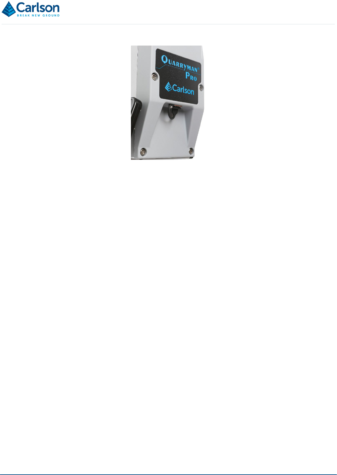
4.1 The Quarryman Pro LR
The Quarryman Pro LR instrument incorporates a laser module held between two pivots within a yoke. The laser
module houses the optical and electronic components that allow distance measurements to be recorded to
reflectorless targets up to 1,200 m from the instrument. The laser module rotates vertically within the yoke.
The yoke itself contains the vertical motor which drives the movement of the laser module between the pillars of the
yoke. It also houses the vertical encoder which measures the angle through which the laser is rotated.
The horizontal housing contains the horizontal motor which drives the rotational movement of the yoke. It also
houses the horizontal encoder which measures the angle through which the yoke is rotated.
The combination of the two axes of rotation gives the Quarryman Pro LR a view that encompasses 360° horizontal
and 135° vertical rotations. The yoke itself prevents the laser from viewing a 90° sector of the vertical rotational axis
looking down to the ground beneath the instrument.
Laser module
Telescope
System ‘power
on’ indicator light
Levelling bubble
Yoke
USB port
Horizontal
housing
Tribrach
Power
connector
Carrying handle
with GPS mount
Figure 2 Component parts of the Quarryman Pro LR

Page | 11
Both motors are protected with clutches. This means that if the unit is rotated by hand or prevented
from moving by an obstruction, the motors will not be damaged. It is advisable, however, to minimise
any manual movement of the unit and to keep the instrument away from potential obstructions so the
motors may turn freely. Nevertheless, the possibility of finger or clothing entrapment exists. Users
should not obstruct the operation of the motors or allow clothing to come into contact with the device.
4.2 Control Display Unit (CDU)
The CDU allows you to control the Quarryman Pro LR: to input data and commands and to view the operation and
status of the unit. The CDU is integrated into the yoke. It incorporates a keypad and screen.
NOTE: The memory in the CDU is protected by a small coin battery, which in normal use should last 10 years before
requiring replacement. The battery ensures that the time and date are retained. If this battery needs replacing, this
must be carried out by an engineer at a Carlson-approved service centre.
The 3.5 inch screen is sun-readable, and has a 320 × 240 resolution display.
The keypad has 17 buttons, some of which have a dual use or can be used in conjunction with other buttons in a
sequence of button presses.
All multi-button combinations result in feedback (e.g. a dialog box or change of screen) to confirm the appropriate
action has been taken, so the buttons should be pressed until the feedback is registered.
4.2.1 Primary button functions
Speed up / speed down
Fire
Function
Scroll
Figure 3 Control Display Unit (CDU)

Page | 12
Enter
Home
Numerals
4.2.2 Secondary button functions
Power on
FastScan pause / resume
FastScan abort
Motorised movement - left
Motorised movement - right
Motorised movement – up
Motorised movement - down
4.2.3 Battery selection
To use a lead acid battery
hold for 5 seconds during power up
Toggle between lead acid /
lithium ion batteries
+
from the main menu

Page | 13
4.2.4 Data entry
Confirm values and continue
Move the cursor to the left
Move the cursor upwards
Move the cursor forwards
4.2.5 Quick-start quide
A sticker showing the most common buttons required during a survey is displayed on the flat of the yoke.
4.3 Laser module
The Quarryman Pro LR laser has a 1,200 m reflectorless range.
The minimum calibrated range of the laser is 10 m. At shorter distances, readings may still be recorded, but their
precision will be severely diminished. At distances up to 20 m, there is a chance that it will be difficult to record data
from surfaces with very low reflectivity.
The two 50 mm lenses within the laser module are the transmitting and receiving optics. It is through these optics
that the infrared measuring laser is fired and its reflected light is then received back into the instrument.
A third, smaller window protects the visible red dot pointer laser which can be turned on to assist aiming the
Quarryman Pro LR in low light conditions.
The laser module incorporates a rifle-style telescope that is used for aiming the laser.
Figure 4 Quickstart guide

Page | 14
4.4 Telescope
The sighting telescope is mounted on the laser module. The telescope is designed to be used with a separation
between the eye and the eyepiece. This allows much easier operation of the system when operating over prolonged
periods.
The magnification is ×1.5 – 4. This is adjustable using the central zoom ring. The focus ring is on the end of the
telescope and can be adjusted to sharpen the image.
The telescope is aligned to be coincident with the laser beam at the unit’s maximum operating range. This means
that there is effectively a vertical offset between the centre of the cross hairs and the scanning laser of up to 60 mm
for near-field targets. This offset will generally only be noticeable at very short ranges.
WARNING: do not look through the telescope while using the laser pointer.
4.5 Yoke
The laser module is mounted between the pillars of the yoke. The yoke itself is mounted on the horizontal housing.
Encoders in the yoke and horizontal housing provide vertical and horizontal angular measurements respectively.
Angles are measured to one hundredth of a degree.
When mounted in the yoke, the laser has movement through −55° (below horizontal) to +90° (above horizontal) in
the vertical. The handle will restrict ranging at upper vertical angles but can be removed if required with a 6 mm hex
key.
Motorised movement of the yoke – and the laser module held within it – is controlled via the keypad. There are four
direction buttons on the right-hand side of the display: 2 = up, 4 = left, 6 = right, 8 = down. On pressing each button,
the motor will operate at the speed that has been set with the SPEED UP / SPEED DOWN buttons on the left of the
keypad. The speed buttons can be used at the same time that the unit is being moved. The default speed is the
slowest possible speed which is most commonly used for fine aiming.
Clutches also allow the system to be moved manually. Large movements of the laser module should be carried out
manually, whilst finer aiming can be achieved more precisely with the motorised controls.
Transmitting
optics
Red dot
pointer
Receiving
optics
Telescope
Figure 5 Quarryman Pro LR Laser module

Page | 15
A level bubble is installed on the crossbar of the yoke to allow accurate levelling of the Quarryman Pro LR. This can
be achieved by varying the length of the tripod legs, and then by adjusting the foot-screws on the tribrach.
4.6 Carrying handle with GPS mount
While the Quarryman Pro LR is out of its transit case, use the carrying handle to transport the instrument around a
site.
If necessary, use a 6 mm hex key to remove the carrying handle. This will allow the laser an unrestricted view
vertically upwards. This may be required if, for example, you are scanning an underground chamber and require a
complete view of the roof above the instrument.
The carrying handle incorporates a 5/8 inch thread. This can be used when you need to establish the position of the
Quarryman unit using a GPS system. Use the supplied 5/8 inch male-to-male adaptor to mount a GPS antenna to
the handle.
The vertical distance from the embossed cross on the side panel to the top of the handle is 141 mm.
The height of the knurled centre of the 5/8 inch male-to-male adaptor is 8 mm.
Thus, when mounting a GPS antenna on the handle using the 5/8 inch male-to-male adaptor supplied, there will be
a total vertical offset of 149 mm from the embossed cross on the side panel to the base of the GPS antenna.
Figure 6 Carrying handle
Figure 7 5/8 in male to male adaptor loose, and on the carrying handle

Page | 16
4.7 Tribrach
The yoke is mounted in a tribrach. The three mounting feet in the base of the yoke unit fit into the corresponding
holes in the tribrach and a latch holds the Quarryman Pro LR in place. The tribrach allows the system to be mounted
on a tripod with standard 5/8 inch thread. Use the tribrach’s foot-screws to level the instrument, with reference to
the levelling bubble on the yoke.
A circular bubble on the tribrach can be used for rough levelling of the tripod and tribrach before the Quarryman Pro
LR itself is attached. However, always use the bubble on the yoke of the Quarryman Pro LR for accurate levelling
of the instrument before starting a survey.
The tribrach incorporates an optical plummet which is required if the Quarryman Pro LR needs to be set up over a
fixed survey station.
Figure 8 Dimensions from embossed cross on side panel to GPS mount point
Offset to top of
carrying handle:
141 mm
Offset to top of knurled
centre of 5/8 inch
male-to-male adaptor:
149 mm
Figure 9 Tribrach
Page | 17
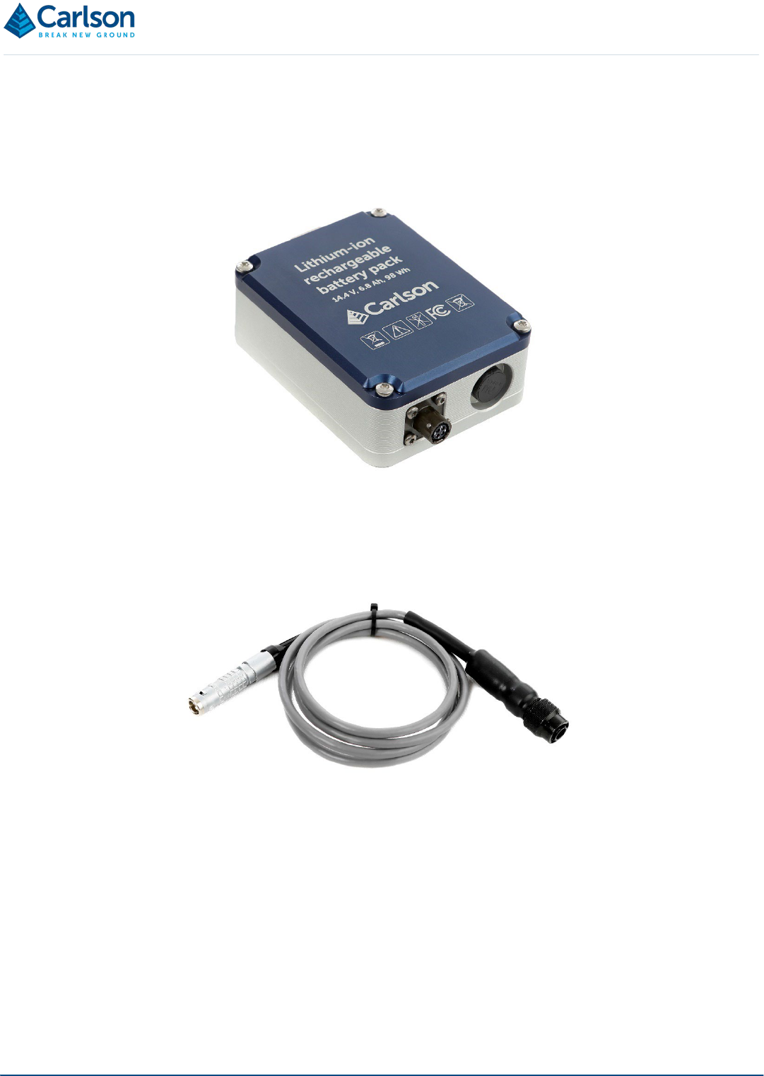
4.8 Battery pack
The Quarryman Pro LR is supplied with a dedicated 14.4 V dc lithium-ion battery pack. The battery pack is rated to
6.8 Ah, and will allow continuous scanning operation for at least 3.5 hours before recharging. This time will reduce
at cold temperatures: 3 hours’ operation would be expected at -20° C.
The battery pack incorporates a bayonet connector with four pins.
This connector will accept the main Quarryman Pro LR power cable which runs directly from the instrument.
Push the connector on the power cable onto the battery connector and turn it clockwise to lock it in place. Turn the
connector anti-clockwise and pull to disconnect.
The other end of the power cable is a silver lemo connector. Match the red dot on this connector to the corresponding
red dot on the power connector on the side of the Quarryman Pro LR. Push the lemo connector into the Quarryman
Pro LR until it clicks securely in place.
Figure 10 Battery pack
Figure 11 Power cable

Page | 18
The battery pack has a mounting bracket which allows it to be hooked onto a tripod.
A separate battery charger is supplied, which plugs directly into the mains and connects to the battery pack through
the 4-pin connector.
Only the supplied battery charger should be used to charge the Quarryman Pro LR battery. A fully discharged
battery requires around six hours to fully recharge from the mains supply. The battery charger is supplied with a
selection of plug types to fit mains sockets around the world. An LED on the charger will show a flashing green light
while charging and a solid green light when the battery is fully charged. A flashing red light is shown if the battery
charger develops a fault.
Figure 12 Quarryman Pro LR connected to the battery pack
Figure 13 Battery charger

Page | 19
When the lithium-ion battery drops beneath 12.5 V dc, the Quarryman Pro LR will carry out a controlled shut-down.
All batteries contain highly reactive, poisonous and corrosive chemicals, which are hazardous if
released due to physical damage. Should the battery or battery charger approach end-of-life, become
non-functional or damaged, stop using it and source a replacement unit from a Carlson-approved
source.
4.9 Alternative power connections
In addition to the lithium-ion battery pack, the Quarryman Pro LR may also be powered from a 12 V dc battery using
the blue cable supplied. This cable incorporates two crocodile clips which connect to the positive (red) and negative
(black) terminals of the battery. The minimum requirement for a lead acid battery is 12 V, 7 Ah, 84 Wh. Larger
batteries can also be used.
The crocodile clip cable contains an in-line fuse. A 5A automotive blade fuse is used.
The Quarryman Pro LR will also run with an old-style lead acid battery (part number A-5914-0222). However, in this
case, the old power cable (part number A-5915-0200) and the old battery charger (part number A-5914-0223) must
be used in conjunction with the old battery, as the connectors on the new equipment are slightly different. The lemo
power connector on the Quarryman Pro LR itself has not changed.
Figure 15 Old-style lead acid battery pack
Figure 14 Crocodile clip DC cable (left) - attached to a 12 V battery (right)

Page | 20
By default, the Quarryman Pro LR is connected to the standard lithium-ion battery supplied. If a lead acid battery is
used instead, whether with the blue crocodile clip cable or the main power cable, you will need to press the 5 button
on the keypad for three seconds when powering the Quarryman Pro LR ON. Alternatively, from the main menu,
press the FUNCTION key and 5 key together to toggle the battery selection between lead acid and lithium-ion.
It is necessary to carry out this procedure because of the different voltages and discharge profiles of lithium-ion and
lead acid batteries. If you do not identify the battery as lead acid, the Quarryman Pro LR will assume that it is
connected to a discharged lithium-ion battery. In this case, very soon after it is turned on, the Quarryman Pro LR
will display a low battery warning and carry out a controlled shut-down.
The battery type will be displayed on the start-up splash screen. It will also be displayed on the battery indicator in
the status bar as either Pb (lead acid) or Li (lithium-ion).
If a lead acid battery is being used at a voltage of less than 10.8 V dc, the Quarryman Pro LR will carry out a
controlled shut-down due to low power.
Any voltage source connected to the Quarryman Pro LR must be within the specified voltage range. This
includes car batteries as an acceptable stand-alone power source but does not include a car battery
connected to a powered vehicle, or a dc power generator.
4.10 USB drives
Three USB drives are supplied with the Quarryman Pro LR. During all operations with the Quarryman Pro LR, data
is stored in a USB drive inserted into the instrument.
The USB drives fit into the USB port on the side of the Quarryman Pro LR.
The USB port is sealed and waterproof. A rubber plug with lanyard is connected to the Quarryman Pro LR and can
be used to physically protect the USB drive when no USB drive is connected to the unit.
Figure 16 Charge indicators for lead acid & lithium-ion batteries
Figure 17 USB drive attached to the Quarryman Pro LR
Page | 21
NOTE: A USB drive must be inserted into the Quarryman Pro LR’s USB port before the instrument is switched on.
This drive must not be removed before the instrument is switched off.
If the USB drive is removed while the Quarryman Pro LR is on, or if it is not present when the instrument is switched
on, a USB error appears on screen. In this case you will need to power down the Quarryman Pro LR by unplugging
the power source.
The USB drives supplied are ready to use. It is recommended that the USB drives supplied are used exclusively for
the Quarryman Pro LR operations and that after data has been downloaded to a PC it is deleted from the USB
drive.
If a new USB drive is used which has not been supplied by Carlson, you need to confirm that it will fit in the location
provided on the side of the Quarryman Pro LR. It may also be necessary to format the drive to allow it to be
compatible with the Quarryman Pro LR.
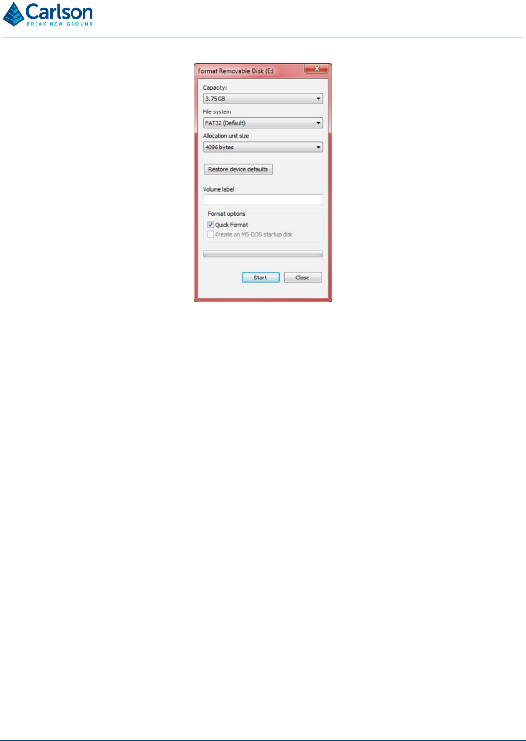
The USB drive can be formatted on a PC. In Windows Explorer (Windows XP, 7, 8 and 10) right- click on the USB
drive and select Format from the context menu. Select the options as shown in Figure 19. The capacity will depend
on the individual drive.
Figure 18 Plastic cover over the USB drive
Page | 22
Click Start to format the USB drive.
The USB drive can also be formatted on the Quarryman Pro LR itself. If a USB drive is connected to the Quarryman
Pro LR that has not been previously used on the instrument or formatted on a PC, or has less than 100 MB of free
space, the Quarryman Pro LR will request to reformat the USB drive when the instrument is powered up. If you
proceed with the reformatting, all data on the USB drive will be lost. For further details see section 6.2.
4.11 Tripod
The Quarryman Pro LR may be supplied with a standard survey tripod. The tripod’s 5/8 inch screw attaches to the
tribrach and holds the instrument secure during operations. Ensure this screw is securely fastened before using the
Quarryman Pro LR.
The tripod should always be set up on stable ground and, where possible, the feet should be dug into the ground
before the instrument is attached and levelled.
Use the screws on the legs to adjust, then fasten, the length of the legs so that the Quarryman Pro LR telescope
and CDU are at a level appropriate to the height of the operator.
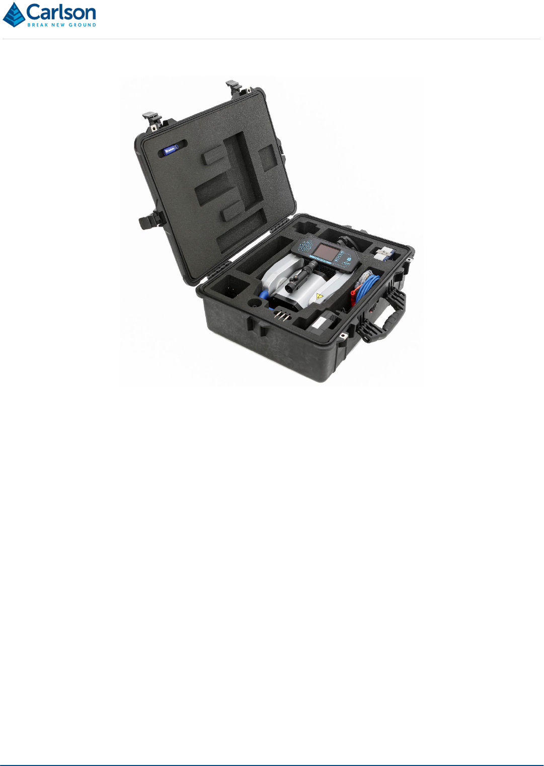
4.12 Transit case
The Quarryman Pro LR system is supplied in a rugged transit case designed to transport the instrument and all
accessories, except the tripod. The case helps to protect the instrument from minor shocks and from the
environment. It is recommended that the transit case be used at all times when transporting and storing the
equipment.
Take care to clean and dry the Quarryman Pro LR and accessories before packing them into the transit case.
Figure 19 Formatting the USB drive
Page | 23
Figure 20 Transit case

Page | 24
5 Maintenance and care of the Quarryman Pro LR
5.1 General
Attempts to dismantle or repair the Quarryman Pro LR and accessories can be hazardous and costly if attempted
by untrained personnel. Unauthorised attempts to carry out maintenance work on the equipment will void all
warranty cover. Maintenance carried out by the operator therefore, should be restricted to the cleaning and
inspection of external surfaces, lens windows and operating controls.
In addition, you should carry out regular functional testing of the system. Detect and report damage, malfunctions
or poor performance to Carlson or a local Carlson representative.
Arrange a yearly calibration for your Quarryman Pro LR system to ensure that it is kept in optimum condition and to
ensure the highest possible quality of data.
A troubleshooting guide which outlines some of the most common support questions is included in section 9. For
issues not dealt with below or in the troubleshooting section, contact Carlson or a local Carlson representative for
further assistance.
5.2 In Use
Avoid directing the Quarryman Pro LR laser towards the sun or other high-power infrared light sources.
Avoid mechanical shock.
Ensure the tripod or other mounting system is securely set up and on stable ground to avoid the instrument being
disturbed or knocked over. When moving from one instrument set-up to another, always detach the Quarryman Pro
LR from the tripod and carry the two items separately. For best stability, ensure the legs are at least 70cm apart
when not extended and at least 110 cm apart when fully extended.
The supplied battery pack will benefit from being kept fully charged and receiving steady use. Recharging the battery
after a short period of use will not affect its performance or life expectancy.
Inspect and check the probe and accessories for wear, tear and damage after each use.
Always clean and dry the equipment after use. See below for details.
5.3 Cleaning the Quarryman Pro LR
Always ensure that the Quarryman Pro LR and all accessories are thoroughly cleaned and dried before packing
them in the transit case after a deployment.
Use clean water to remove mud, grit and other materials from the main body of the probe after use. Do not immerse
the Quarryman Pro LR in water. The Quarryman Pro LR is rated IP66: it is dust-tight and protected against high
pressure water spray from all directions, but not against submersion.
For further cleaning of the Quarryman Pro LR metalwork and plastic side panels, Carlson recommends that you
use a product such as Amberclens anti-static foam cleaner. If this is not available then use a generic, mild
dishwashing liquid diluted in warm water (0.001%, i.e. 1 ml for every 1l of water). Do not use paint solvents or any
other personal, laundry, or household cleaning detergents as they may contain chemicals that could corrode seals
in the Quarryman Pro LR. Apply the diluted detergent with a non-abrasive, lint-free cloth.
Rinse the unit with plain water after using a detergent.
Dry the unit thoroughly after cleaning. Where possible, leave the unit unpacked until it is dry. In case the system is

Page | 25
packed before it has dried, the equipment should be unpacked at the earliest opportunity. Clean and dry the system,
and the inside of the transit case, before repacking the Quarryman Pro LR for storage.
To clean the lens windows and the red dot laser pointer window on the laser module, use HPLC-grade (> 99.8%)
acetone in combination with lint-free cotton wool buds or wipes.
NOTE: repeated exposure to acetone may cause skin dryness or cracking. It is recommended that personal
protective equipment (PPE) such as eye-shields and/or face-shields as well as protective gloves is used when
dispensing and using HPLC-grade acetone.
5.4 Storage and transportation
Dry the system thoroughly before storing.
If the instrument remains unused for several weeks, it is advisable to remove power sources from the instrument.
Store within the environmental temperature limits of -25° C to +70° C.
Before transporting the Quarryman Pro LR system, pack the equipment correctly in the supplied transit case.
Secure the transit case to prevent the possibility of shock or vibration.
Do not allow the transit case to slide around inside transport vehicles or containers.

Page | 26
6 Using the Quarryman Pro LR
6.1 Data files
All data collected by the Quarryman Pro LR is stored in a binary FSC file called QM_nnn.FSC, where nnn is a
sequential number starting at 001. Each time the instrument is switched on, it will check whether any files named in
this way are present and will then offer a choice of either appending to the highest numbered file, or starting a new
file QM_nnn+1.FSC.
The files are stored on the root directory of the USB drive. Files that have been moved to another directory location
on the USB drive will not be detected by the Quarryman Pro LR.
FSC files cannot be deleted while the USB drive is connected to the Quarryman Pro LR. This must be carried out
on a PC prior to the USB drive being connected to the instrument. It is recommended that files on the USB drive
are backed up on a PC as soon as possible. Once the files on the PC have been verified and processed, it is
recommended that they should then be deleted from the USB drive.
The date and time will be added to the file’s properties when the Quarryman Pro LR is powered down.
The FSC file format is the same as that used in previous versions of the Quarryman Pro and Quarryman Pro LR.
If the USB drive is removed while the Quarryman Pro LR is still powered on, the FSC file may not be terminated
correctly and could potentially be corrupt as far as any processing software is concerned. If power is suddenly
removed from the instrument without allowing a controlled shut-down, the same problem may result.
If the Quarryman Pro LR detects a power source that dips beneath a critical level, the instrument will carry out a
controlled shut-down and the FSC file will be correctly terminated.
6.2 Startup
With the USB drive in the USB port, use the FIRE button to turn ON the Quarryman Pro LR. The instrument is turned
OFF from the main menu. See section 6.3.
After turning ON the instrument, a splash screen appears.
The information displayed includes:
• Serial number
Figure 21 Splash screen

Page | 27
• Last calibration date
• Display board firmware version
• CDU board firmware version
• Check on battery voltage
• Battery type selected (default lithium-ion or user-selected lead acid)
• Checks on USB formatting and available memory
• Checks on motor controller
If the USB drive is not present, an error appears on the splash screen showing ‘USB Setup Fault’. Turn off the
instrument by disconnecting the power source, insert the USB drive and power up again.
If the USB drive has not been formatted correctly, an error message appears as shown in Figure 24.
In this case, press ENTER to reformat the USB drive or press 1 to abort the boot-up sequence. If the reformat option
is selected, this process will take around one minute, after which the instrument will turn itself off. All data on the
USB drive will be deleted when it is reformatted.
Once the start-up checks are complete, the instrument searches for existing FSC files on the USB drive. Only files
named QM_nnn.FSC will be recognised. If no such files are found, the unit displays a message stating that a new
file will be created: QM_001.FSC. Press ENTER to continue.
If any valid FSC files are detected, the unit identifies the one with the highest sequential number. An option is then
given to either append to this file, or to start a new file. In the case shown in Figure 26, file QM_001.FSC was found.
Figure 23 Data not found
Figure 22 USB drive error and reformatting

Page | 28
To append to this file, press ENTER. To start a new file – QM_002.FSC – press 1.
Once the current FSC file is determined, the laser module moves vertically to find the zero mark on the vertical
encoder.
Note that the battery indicator is not active until the main menu screen is reached.
A window appears prompting for initial values:
• Station ID: the identification number of the instrument setup.
• Instrument height: the vertical height from the ground beneath the Quarryman Pro LR to the embossed
cross on the side panel of the instrument.
• Backsight heading (degs): by default, this will be 00.00°. Usually when using data from the Quarryman
Pro LR in blast design packages, this value should be left at 00.00°.
These values cannot be entered again without shutting the unit down first.
As with all data entry windows, use the ENTER button to confirm each value, to progress to the next value and to
continue to the next screen. Use the SCROLL button to move the cursor to the left. Use the HOME button to move
the cursor to the right. Use the FUNCTION button to move the cursor up to the previous data entry box.
Having entered the initial parameters, the instrument prompts you to shoot to the back-sight or reference object.
Figure 24 Data file found
Figure 25 Finding zero on encoder
Figure 26 Enter parameters

Page | 29
Sight the laser manually, or using the motorised controls, and press FIRE. This determines the initial 0.00° (or other
value entered as the Backsight heading) position of the horizontal encoder. No point is recorded.
The main menu appears.
6.3 Main menu
From the main menu, all functions of the Quarryman Pro LR are accessible.
1. Point and shoot: single shot operations. See section 6.4.
2. FastScan: scanning operations. See section 6.5.
3. AutoFix: manual rapid fire mode. See section 6.6.
4. Toggle last hit mode on and off. See section 7.4.
5. Toggle the red dot pointer: turns the visible pointer on and off.
6. Adjust saved user settings. See section 6.7.
7. Adjust date and time. See section 6.8.
0. Power off: the unit is powered OFF from the main menu. Press 0 and you will be offered the choice of either
continuing the shut down process or aborting and remaining on the main menu screen. Press ENTER to
continue or HOME to abort.
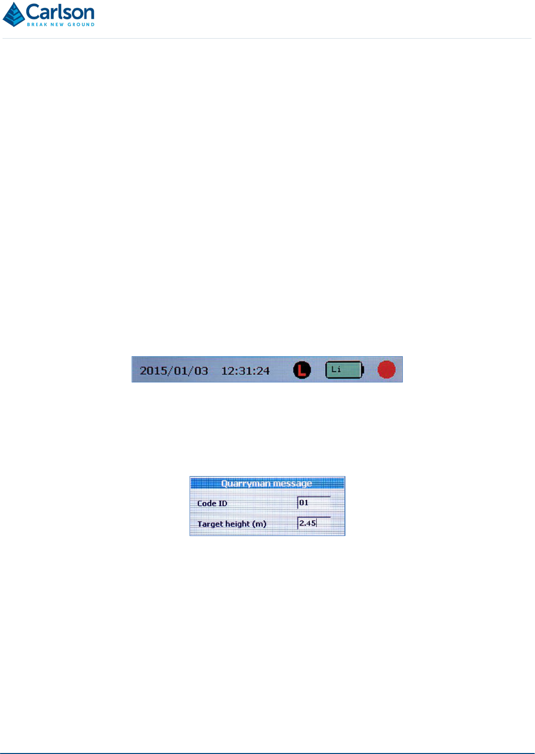
6.3.1 Status bar
The status bar can be seen at the top of the main menu and is present during all survey operations. The status
bar shows:
Figure 27 Shoot to reference object
Figure 28 The main menu
Page | 30
• Date: the date is set in the factory but can be reset by the user: see section 6.8. The date and time are
displayed in the international standard notation: YYYY MM DD / HH:MM:SS.
• Time: the time is set in the factory but can be reset by the user: see section 6.8. The time is displayed in
the 24 hour format.
• Last-hit mode status: A greyed out ‘L’ symbol indicates that last-hit mode is turned off; a red ‘L’ on a black
background indicates that last-hit mode is turned on.
• Battery status: gives a colour-coded representation of the battery status.
o Green: more than 50% charge
o Orange: more than 15% charge
o Red: less than 15% charge. You should consider changing the battery, as the time remaining will
be unpredictable. The instrument shuts down when the voltage from the lithium-ion battery drops
to approximately 12.5 V (if a lead acid battery is being used, this figure will be approximately 10.8
V).
The battery status also shows ‘Li’ or ‘Pb’, depending on whether a lithium-ion or lead acid battery is being
used.
• Red dot pointer status: a black circle indicates that the red dot pointer is turned off; a red circle indicates
that the red dot pointer is turned on.
6.4 Point and shoot mode
On selecting Point and shoot mode, the user input screen appears.
Enter these values as required, then press ENTER.
The Point and shoot survey screen appears.
Figure 29 Code and target height entry

Page | 31
In Point and shoot mode you can move the laser either manually or by using the motor controls. You can take
single shots using the FIRE button. These observations will be recorded under the selected Code ID and Station
ID numbers.
To exit Point and shoot mode at any time, press ENTER to return to the main menu.
The display beneath the status bar shows the following values in real time:
• H Angle: current horizontal angle.
• V Angle: current vertical angle.
• Range: last measured range displayed in metres or feet depending on whether you are using metric or
imperial units of measurement: see section 6.7.
• Est.Time: displays 00:00:00 in Point and shoot mode. During a scan, this displays the time remaining
when a scan is in progress.
• Points: number of recorded points since the current Point and shoot operation was started.
• Laser: displays OFF in Point and shoot mode, and ON when the laser is scanning during FastScan or
AutoFix operations.
• Storage: shows a diagnostic message related to the USB drive connected to the Quarryman Pro LR. There
are three possible messages:
o OK: there is over 100 MB free memory left, and no errors detected.
o ERR: the USB device is not present or has failed.
o LOW: the free space available has dropped below 100 MB.
• Station ID: current station number. This can only be defined when the unit has just been switched on: see
section 6.2.
• Code ID: current user-defined code number. Return to the main menu and re-select Point and shoot mode
to change the Code ID.
• Target ht: current user-defined target height. Return to the main menu and re-select Point and shoot
mode to change the target height.
• Status: displays a message indicating the instrument’s current operational status or diagnostic information.
Figure 30 Point and shoot survey screen

Page | 32
For example:
o Survey in progress
o USB error
• Speed: displays the currently set motor speed. The default value is 1%, which is the slowest speed
available. This value can be altered with the SPEED UP / SPEED DOWN buttons.
6.5 FastScan mode
Select FastScan mode from the main menu to use the Quarryman Pro LR’s scanning functionality. The various
options available are described below. Further information on the concepts involved are outlined in section 7.3.
FastScan settings
The FastScan settings screen appears.
Select the options required for the scan. Some of the options will be greyed out, having already been determined in
the Saved settings screen: see section 6.7. For regular users that have a predictable sequence of operations for
face profiling, this will save having to select the full configuration for each scan.
The settings displayed are:
• Units: only configurable from the Saved settings screen.
• Increment: select Arc or Chord.
• Scan Pattern: select Horizontal, Vertical or Both.
• Scan Speed: select Fast, Medium or Slow.
• Chord Length: enter a value in metres or feet. The default value is configured in the Saved settings
screen. This option will not be visible if Arc increment has been selected.
• Arc Segment: enter a value in degrees. The default value is configured in the Saved settings screen. This
option will not be visible if Chord increment has been selected.
• Scan Code: enter a code for the scan. The default value is configured in the Saved settings screen.
For each option, use the SCROLL button to select, and the ENTER button to accept. Use the FUNCTION button to
move to the previous, active option. When all the values have been entered, a window prompts you to either:
• press ENTER again to accept the settings and continue with the scan or,
• press the HOME button to abort the scan and return to the main menu.
Figure 31 FastScan settings screen

Page | 33
For more information on the scan options, see section 7.3.
6.5.1 Defining the scan window
On accepting the scan settings, you are prompted to select the scan window as a polygon of points shot with the
laser.
Use the telescope to point the laser around the desired scan area, then use the FIRE button to record each point,
up to a maximum of 25. A minimum of two points are required to generate a scan window. The scan window is
effectively a rectangle drawn around the outermost points selected. The sequence of points can be shot in any
order.
Select a circular scan by shooting two points, one vertically above the other at a horizontal separation no greater
than 4°. The vertical separation will define the extent of the scan. This scan mode can be useful in an underground
environment, for example where a complete 360° scan of a cave is required.
As the points defining the polygon are recorded, they will each be displayed onscreen as vertical and horizontal
angles.
Once all the required data points in the polygon have been recorded, press ENTER to continue
You are then prompted to fire a shot inside the selected area. This shot confirms the area to be scanned, as the
selected area could cover a range greater than 180° horizontally. Also, when the scan density is being defined by
Figure 32 Accept scan settings
Figure 33 Polygon select
Figure 34 Polygon select with five points recorded

Page | 34
a chord distance, the shot will provide the distance necessary to calculate the angle required between each scan
line.
The scan will commence immediately after the reference shot has been taken.
6.5.2 During a scan
During a scan, the FastScan survey screen displays the following information. All details are continuously updated.
• Time remaining graphic: a green bar illustrates the percentage of the scan that is complete.
• H Angle: horizontal encoder angle
• V Angle: vertical encoder angle
• Range(m)
• Est time: time remaining – in hours, minutes and seconds.
• Points: displays the total number of points collected during the current scan.
• Laser: displays ON while laser is firing.
• Storage: displays OK if the USB drive is present and has at least 100 MB free memory.
• Station ID: as chosen at the start-up phase.
• Code ID: as selected in the FastScan settings screen.
• Target ht(m): automatically set to 0.00 for FastScan operations.
• Status: Scan in progress.
At any stage while the scan is in progress, you can pause the scan by pressing the FIRE button. The Quarryman
Pro LR completes the current scan line and then pauses. The Status label reads ‘Scan Paused’.
Press the FIRE button again to resume the scan, or press the FUNCTION button to abort the scan. An aborted scan
is acknowledged with a ‘Scan Complete’ dialog box.
When a scan is complete or is aborted, the data collected is stored on the USB drive and the display returns to the
main menu.
Figure 35 Scan in progress

Page | 35
6.6 AutoFix mode
Select AutoFix mode from the main menu to use the rapid fire option. AutoFix mode can sometimes be a more
efficient way of collecting specific data, rather than carrying out a full FastScan: for example, when surveying the
break-lines of a stockpile or a long sequence of points defining a crest.
A message window prompts for a change in Code ID. Enter a value to progress to the AutoFix survey screen.
The target height is automatically set to 0.00 for AutoFix operations.
The header displays ‘AutoFix in progress. Press ENTER to stop’. The Status label displays ‘Scan in progress’.
The rapid fire AutoFix function shoots approximately 30 points per second. The laser triggers when the laser module
is moved at an angular speed greater than 2° per second. Until this point, the Laser label displays OFF. Once the
laser is firing, the Laser label displays ON.
To finish using AutoFix mode and return to the main menu, press ENTER.
6.7 Saved settings
Select ‘Adjust saved user settings’ from the main menu to change the default set-up of the Quarryman Pro LR.
NOTE: when all settings have been entered, the Quarryman Pro LR powers itself OFF to save the selected
configuration. A message appears offering the chance to either save the settings and shut down the instrument, or
to abort any changes and return to the main menu. Press ENTER to continue or HOME to abort.
This screen offers the chance to configure some preferred options. For regular users who have a predictable
sequence of operations, this will save having to select the full configuration for each scan. For example, you may
always use the instrument for face profiling and will always require a Horizontal scan, using a Chord interval of 0.4
Figure 36 AutoFix mode
Figure 37 Saved settings screen

Page | 36
m, with a Code ID of 50 and using the Fast speed setting. Once selected in the Saved settings screen, these
options do not then have to be selected each time the instrument is used.
Note that if any values are set to Manual, these options will be configurable each time a FastScan operation is
initiated. Therefore, if the Quarryman Pro LR is regularly used in a variety of different ways, leave all settings as
Manual.
The options that can be changed are:
• Units: only configurable from this screen. Options: Metric or Imperial.
• Increment: select Arc, Chord or Manual.
• Scan pattern: select Horizontal, Vertical, Both or Manual.
• Scan speed: select Fast, Medium, Slow or Manual.
• Chord (m): enter a value in metres or feet. This value then appears as the default value when FastScan is
selected, but can be changed as required for each survey. The Chord Length option will not be visible if
Arc increment has been selected.
• Arc (degs): enter a value in degrees. This value then appears as the default value when FastScan is
selected, but can be changed as required for each survey. The Arc Segment option will not be visible if
Chord increment has been selected.
• Scan code: enter a code for the scan. This appears as the default value when FastScan is selected, but
can be changed as required for each survey.
6.8 Date and time settings
Select Adjust date and time to set the current date and time used by the Quarryman Pro LR
The time and date are set in the factory, but you may need to reset the values if the unit has crossed time zones or
there are daylight-savings time changes.
NOTE: when the date and time has been entered, the Quarryman Pro LR powers itself OFF to save the selected
configuration. A message appears offering the chance to either save the changes and shut down the instrument, or
to abort any changes and return to the main menu. Press ENTER to continue or HOME to abort.
The following values can be set. Each requires two digits. Press ENTER to accept each value and then ENTER
again to save the values to memory.
• Month: MM.
• Day: DD.
• Year: YY.
Figure 38 Saved settings screen

Page | 37
• Hour: in 24 hour format.
• Minutes
• Seconds
The time and date information is written to the CDU board where a clock keeps the values updated.

Page | 38
7 Operational guidelines
7.1 System limitations
The Quarryman Pro is water and dust resistant (IP66 in accordance with IEC 60529:1992+A1:2002) but should not
be submerged.
Under Carlson test conditions, the laser ranges up to a limit of 1,200 m to 90% reflective material (e.g. Kodak white
card), where the target is larger than the footprint of the laser and the angle of incidence is perpendicular to the path
of the laser.
However, the maximum achievable range at any given time or location will depend on a number of factors. The
following factors will limit the range to an unpredictable degree and, in some circumstances, may prevent any
readings from being taken:
• dark, light-absorbent surfaces such as coal
• very dusty environments
• wet, slick, shiny or very smooth surfaces
• an acute angle between the laser and the surface
The Quarryman Pro LR is calibrated and focused for long range applications. If used at distances of less than 20
m, there is a chance that it will be difficult to record data from very dark, unreflective surfaces.
The minimum calibrated range of the laser is 10 m. At shorter distances, readings may still be recorded, but their
precision will be severely diminished.
Do not point the laser directly into the sun. This could lead to spurious points being collected and, as a worst case,
the laser itself could be damaged.
Only use the Quarryman Pro LR when it is mounted on a stable tripod. If you move the tripod, or the position of the
instrument on the tripod, during operations at a single station, the collected data will be invalid. Take care to level
the instrument, secure the tripod in the ground and securely fasten the screws on the tripod legs. For best stability,
ensure the legs are at least 70cm apart when not extended and at least 110 cm apart when fully extended.
Do not use the Quarryman Pro LR to shoot to reflective prisms as the accuracy of recorded ranges may be affected.
Never use a reflective target when last-hit mode is switched on, as this can cause ranges to be observed that are
twice as long as the actual distance.
7.2 Instrument heights and target heights
Once the Quarryman Pro LR has been secured on the tripod and levelled using the level bubble, carefully measure
the instrument height. In the Quarryman Pro LR menu, there is only one chance to enter the instrument height:
when the unit is first switched on. If you enter the instrument height incorrectly at this stage, either restart the
instrument or else note the measurement and enter it later in your processing software.
The measurement of the instrument height is particularly important if multiple data sets from different instrument
positions are going to be stitched together: for example, carrying out a traverse around a stockpile, or taking range
and bearing observations to new instrument positions when a complete quarry face cannot be viewed from a single
location.
In these cases, if you do not enter the instrument height, or you enter it incorrectly, scans taken from different
locations will not match up.

Page | 39
The instrument height is the vertical distance from the ground directly beneath the instrument to the embossed
cross on either of the side panels.
The target height is also important in the examples mentioned above. Only set the target height to a non-zero value
if observing to a target held above the feature to be surveyed.
In the case of a traverse or a range and bearing observation, a target is usually held above the ground over the
point that will be occupied by the Quarryman Pro LR. Therefore measure the height of the target above the ground.
Similarly, when carrying out face profiling operations, the hole collars are not usually visible from the instrument
location on the quarry floor. Therefore a person holding a tall target on a pole should stand over each collar. Use
the Quarryman Pro LR to shoot a single observation to the target at each collar.
Figure 39 Embossed cross on the side panel to measure instrument height

Page | 40
In each case, it is important that you position the target directly above the point on the ground that is being surveyed.
In the case of a manually held target fixed on a tall pole, it is essential that the pole is straight and that there is a
levelling bubble fixed on the pole to help ensure that it is held upright.
As a rough guide, if your Quarryman Pro LR is up to 150 m away from the hole collars, you should use a target at
least 35 cm square. The target should be painted white, made from a rigid material and mounted in line with the
survey pole. Mark a diagonal cross on the target to identify its centre. To assist ranging, attach some reflective tape
at the centre of the target if required.
Change the target height at any time in the survey by accessing the main menu and selecting Point and shoot
mode.
Enter the instrument height and target height in metres, to the nearest centimetre. If imperial units have been
selected in the Saved settings screen, then enter the measurements in feet, to the nearest hundredth of a foot.
Note that the target height is automatically set to zero when FastScan or AutoFix modes are activated. In these
cases the instrument will always be directly shooting to the feature being surveyed – such as a rock face or stockpile
– rather than to a target held above the feature.
7.3 Notes on FastScan options
7.3.1 Defining the scan window
After selecting FastScan operations, you must define the scan window. The scan window outlines the area that the
Quarryman Pro LR will ‘fill-in’ with scan points.
Use the telescope to aim single observations just outside the outlying edges of the scene. Use a minimum of two
points and a maximum of 25 points to define the scan window. The points can be selected in any order.
Figure 40 Target on survey pole being used to position a hole collar

Page | 41
If using two points, select diagonally opposite corners of the rectangle which encompasses the scan window.
If the Quarryman Pro LR is situated in the middle of a long face and only two points are selected to define the
polygon, horizontal scan lines may appear curved along the face, bowing down in the region closer to the instrument.
This is because the vertical angle of the laser remains fixed during each scan line: at shorter distances it will hit a
lower point on the face than at longer distances, as in the picture below. The result is that upper, central portions of
the face may not be covered by the scan.
It is therefore advisable to use multiple points around the face in order to ensure that all required aspects of
a scene are included in the scan.
The Quarryman Pro LR will then construct a ‘best-fit’ rectangle around the defined polygon.
Figure 41 Using two points to define a scan window
Figure 42 'Curved' horizontal scan lines

Page | 42
Activate a circular scan by selecting two points, one defining the upper boundary of the circular scan, the other
defining the lower boundary. These two points should be separated by less than 4° in the horizontal axis, otherwise
the Quarryman Pro LR will assume that a standard rectangular scan is required
As always, the order in which the points are collected does not affect the scan.
When a scan window has been defined, the Quarryman Pro LR prompts you to take a single shot in the middle of
this window. The scan will not commence until a valid range has been registered. This shot serves two purposes.
• It is possible to scan scenes covering a horizontal angle of greater than 180°, so this shot is necessary to
resolve the ambiguity about which of two possible areas is to be scanned.
• When a Chord increment is selected, the range from this single shot is used to calculate the angle which
will need to be subtended in order for the correct chord distance to be achieved.
7.3.2 Scan speed
When a scan is in progress, the laser is observing 250 points per second. This defines the density of points along
a scan line. The data collection speed of the laser cannot be changed.
The only way to change the point spacing along the scan line is to slow the movement of the motors. There is a
Scan Speed setting in the FastScan settings screen.
• Slow = 15° per second.
• Medium = 17.5° per second.
• Fast = 20° per second.
For almost all operations, this setting can be left on the default Fast setting. However, if carrying out a scan where
the highest level of detail is required, or where the scene being surveyed is at a very long range, it may be advisable
to select a Medium or Slow scan speed. The points will still be collected at 250 points per second, but the time it
takes the laser to turn through each degree of arc will increase. In turn, the number of points which are collected
per scan line will increase.
Figure 43 Using multiple points to define a scan window

Page | 43
7.3.3 Chord and arc settings
Chord and Arc modes are selected in the Increment option in the FastScan settings screen.
The Increment defines the spacing between each scan line. This will be the vertical spacing between horizontal
scan lines if a Horizontal scan pattern has been selected, or the horizontal spacing between vertical scan lines if a
Vertical scan pattern has been selected.
The Arc setting requires you to select an angular arc value in degrees. Enter this value in the FastScan settings
screen. The Quarryman Pro LR laser module will move this angular distance at the end of each scan line before
starting the next line.
The minimum Arc value that the Quarryman Pro LR will operate at is 0.05°.
The Chord setting requires you to select a chord distance in metres (or feet if you are using Imperial units). Enter
this value in the FastScan settings screen.
A chord should be used for most operations, as it is much harder to envisage the actual line spacing at a given
distance when using an angular arc value. For example, if the unit is 100 m from the face, what would the line
spacing be if a 0.2° arc spacing was entered? It would be easier to enter a chord of 0.35 m and let the instrument
make the appropriate calculations to determine the required angular movements between scan lines.
If Chord is selected, the Quarryman Pro LR laser module will use the initial single shot – taken after defining the
scan window – to calculate the angle that will need to be subtended in order to achieve the user-defined Chord
value on the face.
Note that the single shot should be taken in the middle of the scene to be scanned, as this will give a rough average
calculation for the whole scene. Once calculated, the same angular increment is used across the whole scan and
is not adjusted if different parts of the targeted scene are at different distances from the Quarryman Pro LR. If the
single shot is taken at a part of the scene that is very close to the instrument, the line spacing for areas further away
Figure 44 FastScan with Arc increment selected
Arc value
selected to
determine scan
line spacing

Page | 44
will be increasingly large. If the shot is taken to a distant part of the scene, the line spacing will be increasingly small
for areas closer to the instrument.
Irrespective of the entered Chord value, the minimum angular increment that the Quarryman Pro LR will operate at
is 0.05°.
7.4 Last-hit mode
The Quarryman Pro LR measures distances by sending a pulse of laser energy out to a target and timing how long
it takes the pulse to reach the target, reflect from it, and return to the receiving optics.
In some conditions, the pulse can be reflected off particles in the air between the laser and the intended target: for
example, if the instrument is in a particularly dusty environment, if there is mist in the air, or if it is snowing.
In these conditions, turn on Last-hit mode. In this mode, the laser will try to filter out the false readings from particles
in the air by concentrating on the pulses which have taken the longest time to return to the laser. These will generally
be the pulses that have penetrated to the targeted surface, rather than those which have been reflected by the
airborne particles.
However, if the conditions are so bad that very few pulses are penetrating to the intended target, then Last-hit
mode will not be able to help. In this case, you may need to postpone the survey until the weather improves or the
dust clears. Alternatively, you may be able to move the instrument to a position where there is a clearer view of the
scene to be scanned.
Note that you should never use Last-hit mode to shoot to reflective targets, as erroneous ranges can result. It is
recommended to leave Last-hit mode off unless it is specifically required.
Figure 45 FastScan with Chord increment selected
Chord value
selected to
determine scan
line spacing

Page | 45
8 Typical operating sequence
The Quarryman Pro LR can be used for a wide variety of jobs in a variety of applications. However, the following
section gives the step-by-step routine for a typical face profiling operation, including a resection. It might be regarded
as a template for any simple operations with the unit and can be modified according to specific project or site
requirements.
8.1 Positioning the Quarryman Pro LR
Set up the instrument, ideally at a distance of less than 100 m from the face to be profiled.
Find the best location where all parts of the face are clearly visible. It may occasionally be necessary to have two
or more instrument set-ups to ensure complete coverage of the face during scanning operations.
Many quarries will have a series of survey stations around the perimeter. Each station is marked by a permanent
target, visible from the quarry floor. The coordinates (x,y,z) of each marker will be known on either a national or
local grid system. There should be enough markers to ensure that wherever the Quarryman Pro LR is situated, at
least three stations will be visible. These stations can be used to carry out a resection. The resection enables the
software to calculate the position of the Quarryman Pro LR within the quarry.
Check that at least three survey stations can be seen. These should ideally be fairly evenly spaced around the
instrument location. If they are all clustered in the same direction, the results of the resection observations may be
poor.
Check that he set-up location will not be disturbed by other personnel or vehicles during the duration of the profiling.
8.2 Setting up the Quarryman Pro LR
Set the tripod on stable ground and ensure that each leg is secure.
The legs of the tripod should be roughly equidistant and the height should be such that, with the instrument mounted
on the tripod, the telescope will be at eye level.
Tighten each leg screw securely at a point where the flat top off the tripod is roughly level.
Mount the instrument on the tripod using the tribrach and tighten the screw to secure the instrument to the tripod.
Ensure that the latch on the side of the tribrach is engaged and holding the instrument securely.
Turn the yoke of the Quarryman Pro LR so the axis of the unit is parallel to two of the three tribrach screws. Using
these two foot-screws, level the instrument in one axis. Observe the bubble on the yoke to check when the
instrument is level.
Turn the yoke 90° so the axis of the unit is perpendicular to the first two tribrach screws. Now use the third screw to
level the instrument in this second axis.
Repeat this stage with the instrument turned 180° to fine-tune the levelling of the Quarryman Pro LR.
Mount the battery on the tripod using the bracket on the rear of the battery pack.
Connect the power cable between the 4-pin connector on the battery pack and the connector on the base of the
Quarryman Pro LR.
Ensure that the USB drive is securely inserted in the instrument.
Measure the height of the instrument with a tape measure. The instrument height is the vertical distance from the

Page | 46
ground directly beneath the instrument to the cross on either of the side panels.
8.3 Switching on and starting the survey
Press the FIRE button on the CDU.
After the initial splash screen, the Quarryman Pro LR will search for FSC files on the USB drive. If no files are found,
the unit will generate a new file QM_001.FSC. Otherwise, the CDU will prompt:
Quarryman data file found
Press ENTER to append to QM_001.FSC
Press 1 to create file QM_002.FSC
Press 1 to start a new file. The laser will move vertically to initialise the vertical encoder. Enter the Station ID (e.g.
01 to indicate the first instrument position) and Instrument Height (measured to the cross on the side panel). For
most operations, leave the Backsight heading as 00.00°.
The laser module will move up and down until the vertical encoder finds its zero position. The CDU will prompt:
Point to backsight
Press FIRE to zero horizontal encoder
Move the laser manually or with the motorised controls to point to your reference station, which will usually be a
known control station. Fire the laser. This will set the horizontal encoder to 0.00° (or other value entered as the
Backsight heading).
At this point the display shows the default main menu and the instrument is ready to take observations.
8.4 Resection observations
Press 1 to select Point and shoot mode from the main menu.
In the subsequent window, enter a Code ID, eg 10, to identify the resection observations. Leave the Target Height
at 0.00.
Press ENTER again to enter the Point and shoot survey screen.
Manual Point and shoot mode is the default operating mode of the Quarryman Pro LR. This screen allows you to
move the instrument and to fire the laser manually to shoot individual points.
Press the FIRE button to take an observation and to log the measured range, horizontal angle and vertical angle to
the USB drive.
Carefully use the telescope to aim to the first survey station. Take a reading with the FIRE button. Repeat with the
second and third survey stations.
Record which targets have been observed, and in which order.

Page | 47
8.5 Toe and crest observations
To take observations to the toe and the crest, you first need to change the code. This will separate the data from
the previous resection observations (which in this case were recorded under code 10).
Press ENTER to return to the main menu. Press 1 to select Point and shoot mode again.
Enter a new Code ID, e.g. 20, to represent the crest. Leave the Target Height at 0.00.
Use the telescope to point the laser at one end of the crest. Now trace the laser along the line of the crest, taking a
series of manual shots along the way.
On completing the crest, press ENTER then 1 to return to the Point and shoot menu. Enter a new Code ID, e.g.
30, to represent the toe. Leave the Target Height at 0.00.
Use the telescope to point the laser at one end of the toe. Now trace the laser along the line of the toe, taking a
series of manual shots along the way.
8.6 Shooting the hole markers
From the perspective of the Quarryman Pro LR on the quarry floor, the hole collars on top of the bench will probably
not be visible. For this reason, a second operator will be required to hold a target over the holes.
The target should be a straight pole with a clear target on top. For example, this may be a small wooden board (at
least 30 cm square) painted white, with a cross identifying the centre of the target.
The pole must have a bubble attached. This will ensure that the pole can be held straight when positioned over the
hole. If the pole is not held upright, or if it is not straight, the calculated hole position will be incorrect.
Measure the distance from the bottom of the pole to the centre of the target. This will be the entered Target Height.
The second operator should hold the target over the first collar.
On the Quarryman Pro LR, press ENTER then, from the main menu, select 1 to return to the Point and shoot
menu. Enter a new Code ID, e.g. 40, to represent the shot holes. Enter the appropriate Target Height then press
ENTER again to return to the Point and shoot screen.
Use the telescope to point the laser to the target over the first hole. Take an observation with the FIRE button.
The second operator should move the target over the next hole collar.
Re-aim the laser to point at the new target position. Take another observation. Repeat until all holes have been
observed.
All these observations will be recorded under the same code: in this case, code ‘40’.
8.7 Scanning the face
When ready to take a scan, press 2 from the main menu to select FastScan operations.
The FastScan settings screen will appear. The drop-down menus will be populated or greyed out depending on
the settings entered in the Saved settings screen.
For standard face profiling operations, select a Horizontal scan using a Chord measurement. Enter the desired
chord length and a Code ID, for example code ‘50’ for a FastScan.

Page | 48
Using the telescope, position the laser to one extremity of the scene to be scanned. Press the FIRE button to register
this point. Continue to define corners of a polygon with the FIRE button until an outline of the scene is fully defined.
When observing the last corner point, the polygon does not need to be ‘joined up’ to the first corner, i.e. a four-sided
polygon only requires four corners to be observed.
Once the polygon is defined, press ENTER. The CDU prompts:
Point laser to centre of scan area and press FIRE
Point the laser to the centre of the scene and press FIRE.
8.8 Scanning
The Quarryman Pro LR will now automatically move into position at the top left corner of the scan window. The scan
will then commence and will require no further user intervention.
On completion of a scan, the laser will return to the centre of the scan area. The CDU will return to the main menu.
If more scans are required to fill in detail on the face, repeat section 8.7, selecting the scan window and point density
as required.
8.9 Completing the survey
On completion of all observations, it is good practice to re-aim the unit to the reference target that was sighted at
the start of operations. Check that the horizontal angle is 0.00° to within a few hundredths of a degree. If this is not
so, it will mean that the unit has moved on the tripod and there may be errors in some of the observations.
Turn the unit off by pressing 0 from the main menu.
On returning to the office, remove the USB drive and back up the new FSC files immediately. Put the battery on
charge.
Ensure the Quarryman Pro LR and accessories are clean and dry before packing away in the transit case supplied.

Page | 49
9 Quarryman Pro troubleshooting guide
9.1 Diagnosis of some common issues
Some of the most common support questions are outlined below. If you experience a problem with your Quarryman
Pro LR system or the resulting data, check the list to find the cause and action, and also a reference to the relevant
section in this manual.
Instrument does not power up
Cause
Remedy
Reference in manual
Power cable not connected. Ensure all connections are
securely connected.
Section 4.8, “Battery pack”
Lithium-ion battery not charged. Ensure the battery is charged prior
to scanning operations.
Section 4.8, “Battery pack”
Power cable damaged. Check all pins, connectors and the
cable itself for signs of damage.
Arrange for repair or replacement.
Contact Carlson or a local Carlson
representative
Instrument shutting down during operations
Cause
Remedy
Reference in manual
Battery is discharged. Swap to a back-up power source or
ensure the battery supplied is fully
charged.
Section 4.8, “Battery pack”
Using a lead acid battery. If using a lead acid battery, press 5
for 3 seconds while the instrument
is powering up. The battery icon on
the status bar will indicate Pb if the
selection has been registered.
Section 4.9, “Alternative external
power connections”
When starting up, the instrument does not progress past splash-screen
Cause
Remedy
Reference in manual
USB drive not plugged in. Power the unit down. Ensure the
USB drive is present and securely
connected. Restart the instrument.
Section 4.10, “USB drives”
‘Noise’ in the scan data during operations
Cause
Remedy
Reference in manual
Laser pointed into the sun. Avoid pointing the laser into strong
sunlight, as this will interfere with
the receiving optics.
Section 7.1, “System limitations”
Standing water, running water or
wet surfaces on the targeted face.
Laser ranging to wet surfaces is
unpredictable.
Section 7.1, “System limitations”
Laser electronics faulty. Arrange recalibration. Contact Carlson or a local Carlson
representative

Page | 50
Multiple scans not matching up or large traverse misclosures
Cause
Remedy
Reference in manual
Initial reference object or back-
sight not targeted correctly.
Ensure the initial reference
observation is precisely aimed and
is pointing to the correct target.
Section 8.2, “Setting up the
Quarryman Pro LR”
Instrument not levelled. Use the bubble carefully to ensure
the instrument is levelled before it
is switched on.
Section 8.2, “Setting up the
Quarryman Pro LR”
Instrument moved during
operations.
Ensure the tripod is secure and the
tribrach is tightly fastened to it.
Section 8.2, “Setting up the
Quarryman Pro LR”
Instrument height not measured
correctly.
Measure from the ground under the
instrument to the cross on the side
panel. Enter in metres or feet.
Section 8.2, “Setting up the
Quarryman Pro LR”
Target height not entered correctly. Only enter a target height if
shooting to a target above the
object being surveyed – e.g. a
target on a pole held above a
traverse station or a hole collar.
Enter in metres or feet.
Section 8.2, “Setting up the
Quarryman Pro LR”
Telescope not aligned with laser. Arrange recalibration. Contact Carlson or a local Carlson
representative
Encoders faulty. Arrange recalibration. Contact Carlson or a local Carlson
representative
Large ‘spread of heights’ from a resection
Cause
Remedy
Reference in manual
Telescope not aligned with laser. Arrange recalibration. Contact Carlson or a local Carlson
representative”
Survey targets moved. Ensure the targets are stable. Have
the targets remounted and
resurveyed if necessary.
Wrong coordinates entered for the
survey targets.
Ensure the coordinates have been
entered correctly in the processing
software and that the correct target
has been matched with the correct
observation.
Incorrect ranges in Point and shoot mode
Cause
Remedy
Reference in manual
Shooting to a reflective prism. Do not use a reflective prism as a
target.
Section 7.1, “System limitations”
Thick dust, mist or snow interfering
with observations.
Switch on last-hit mode. If the
problem persists, wait for dust or
bad weather to clear, if feasible.
Section 6.3, “Main menu”
Shooting into the sun. Avoid pointing the laser directly at
the sun.
Section 7.1, “System limitations”

Page | 51
‘Holes’ in the point cloud
Cause
Remedy
Reference in manual
Standing water or very unreflective
surfaces such as coal are present.
Laser ranging to wet or very dark
surfaces is unpredictable. Try
moving closer to the targeted
surfaces.
Section 7.1, “System limitations”
Surfaces are beyond the range of
the laser.
Set up the Quarryman Pro LR in
another location if possible and
combine scans to overcome range
limitations.
Section 7.1, “System limitations”
Dark surfaces in the scan. Surfaces such as coal can give
severely reduced ranges. Move
closer to the target.
Section 7.1, “System limitations”
Dark surfaces at ranges below 20
m.
Move further away from the target. Section 7.1, “System limitations”
Point cloud is ill-defined and ‘fuzzy’
Cause
Remedy
Reference in manual
Thick dust, mist or snow interfering
with the scan.
Switch on last-hit mode. If the
problem persists, wait for dust or
bad weather to clear, if feasible.
Section 6.3, “Main menu”
Standing water, running water or
wet surfaces present.
None. Laser ranging to wet
surfaces is unpredictable.
Section 7.1, “System limitations”
9.2 Other faults
If you are not able to repair or pinpoint a fault from the table above, you should contact the product support
department at Carlson, or your local Carlson representative for further assistance.

Page | 52
10 Quarryman Pro LR Specifications
Laser module
Laser classification BS EN 60825-1:2014
(21 CFR 1040.10 and 1040.11 except for
deviations pursuant to Laser No. 50, dated 24
June 2007)
Class 3R*
Infrared laser module
Type InGaAs laser diode
Wavelength (typ) 905 nm
Maximum energy per pulse 1.55 µJ
Beam divergence 2.25 × 0.15 mrads
Resolution 1 cm
Maximum range to a passive target** Up to 1200 m
Minimum range 10 m
Lens aperture size and location 46 mm (location at front of module)
Visible laser module
Type InGaAsP laser diode
Wavelength (typ) 650 nm
Maximum power < 0.6 mW (continuous wave)
Lens aperture size and location 3 mm (location at front of module)
Angle
Encoder type Opto-electronic encoder
Encoder accuracy 0.02°
Encoder resolution 0.01°
Mechanical range
Vertical −45° to +90°
Horizontal 0° to 360°
Mechanical motion Stepper-driven worm and wheel drives in both axes with
manual clutch override
Keyboard and display
Display 3.5 inch, sun-readable TFT
Resolution 320 × 240
Keyboard 17-button keypad
Data logging
Supplied logging media 8 GB USB drive
Compatibility USB 2.0 and 3.0

Page | 53
Power
Supplied battery 14.4 V Lithium-ion
Capacity 6.8 Ah
Scan time (typically) 210 min
Alternative power 12 V dc lead acid, minimum 7 Ah
IEC overvoltage category Category II
Physical data
Construction Machined aluminium
Water and dust resistant IP66
UL weather rating Wet location
IEC Pollution degree PD3
Humidity 95% non-condensing
Altitude Up to 5,000 m
Operating temperature range*** –20 °C to +45 °C
Weight 8.0 kg including tribrach
* Visible and invisible laser radiation. Avoid direct eye exposure.
** Maximum measuring ranges are recorded against Kodak white card (90% reflectivity).
*** Visible laser module operational –10 °C to +50 °C*

Page | 54
11 Product information
© 2018 Carlson. All rights reserved.
This document may not be copied or reproduced
in whole or in part, or transferred to any other media or language,
by any means, without the prior written permission of Carlson.
The publication of material within this document does not imply freedom from the patent rights of Carlson.
Trademarks
CARLSON and the symbol used in the CARLSON logo are registered trademarks of Carlson in the United Kingdom
and other countries. ‘Breaking new ground’ and names and designations of other Carlson products and technologies
are trademarks of Carlson or its subsidiaries.
All other brand names and product names used in this document are trade names, trademarks, or registered
trademarks of their respective owners.
Changes to Carlson products
Carlson reserves the right to improve, change or modify its products and documentation without incurring any
obligation to make changes to equipment previously sold or distributed.
Carlson has made considerable efforts to ensure the content of this document is correct at the date of publication
but makes no warranties or representations regarding the contact. Carlson excludes liability, howsoever arising, for
any inaccuracies in the document.
Warranty
Unless otherwise specified, Carlson warrants all supplied equipment for a period of 12 months from the date of
delivery. This warranty is given subject to the following conditions:
• Carlson shall be under no liability in respect of any defects in the equipment arising from any drawing,
design or specification supplied or modification requested by the customer.
• Carlson shall be under no liability in respect of defects arising from wilful damage, negligence, abnormal
working conditions, failure to follow Carlson’s instructions (whether oral or in writing), misuse or alteration
or repair of the equipment without Carlson’s approval.
• Software is not covered by this warranty.
• Claims in respect of defective equipment must be made in writing to Carlson and the equipment must be
retained by the customer pending written instructions from Carlson.
Following authorised return of the equipment, which must be made by the customer on freight prepaid basis, Carlson
will examine the equipment and, if the claim is justified in Carlson’s opinion, will repair the defective equipment or
will make replacement without charge. Carlson will have no further liability to the customer.
Safety
The Quarryman Pro LR laser scanner is a robust, ruggedized, field instrument whose applications include the 3D
mapping of entire quarry or mine sites, determination of 3D rock face geometry, blast design and volumetric
surveying of stockpiles and reserves. Unit range is 1200 metres to non-reflective surfaces. It is essential that the
unit and all accessories are operated in accordance with the instructions in this user manual and it is the
responsibility of the user to ensure that, in the event of a failure on any part of the Carlson system, the equipment
remains safe.
In the case of equipment with powers or speeds capable of causing injury, it is essential that appropriate safety

Page | 55
measures are incorporated into the equipment operation. Further guidance can be found in the European Standard
EN292 Safety of machinery – General principles of design – Risk assessment and risk reduction.
The safety of any operations involving the Quarryman Pro LR system is the responsibility of the operator.
If the equipment is used in a manner not specified by the manufacturer, the protection provided by the equipment
may be impaired.
Information to the equipment supplier/ installer
It is the equipment supplier’s responsibility to ensure that the user is made aware of any hazards involved in any
operations involving the Quarryman Pro LR system, including those mentioned in Carlson product literature.
Laser Safety
DO NOT STARE DIRECTLY INTO THE BEAM
In accordance with BS EN 60825-1:2014 and US standards 21CFR 1040.10 and 1040.11 except for deviations
pursuant to Laser Notice no. 50, dated June 24, 2007, the Quarryman Pro LR laser profiling system is classified as
a Class 3R combined visible and invisible laser product. Operation of Class 3R equipment can present a hazard
not only to the user, but also other people over a considerable distance.
Class 3R laser products are not considered intrinsically safe, however risk is limited by unintentional exposures
rarely reflecting worst-case conditions; natural aversion behaviour to bright light (visible) and response to heating
of the cornea (invisible). Risk of injury increases with exposure duration, and exposure may be hazardous for ocular
exposure under worst-case conditions or for intentional direct intrabeam viewing. Class 3R products should only be
used where direct intrabeam viewing is unlikely.
For all installations, a laser safety officer should be appointed. It is the responsibility of the appointee to review the
precautions and designate the appropriate controls to be implemented. Safety eyewear, designed to provide
adequate protection against the specific wavelength(s), should be used in all hazard areas.
Do not stare into the beam or shine it into the eyes of others. It is safe to view a diffuse-reflected beam. Do not
dismantle the unit in any way; doing so may expose laser radiation in excess of Class 3R combined limits.
CAUTION: laser light is bright and blinding – do not shine at aircraft or vehicles at any distance.
Safety information
This symbol is used in this manual wherever important safety information is present.
Before proceeding with any electrical connection or operation of the laser system, refer to the general
safety information throughout this manual.
EC declaration of conformity
Carlson declares that the Quarryman Pro LR complies with the applicable directives, standards and regulations.
Contact Carlson or visit www.carlsonsw.com
for the full EC declaration of conformity.

Page | 56
FCC (USA only)
Information to the user (47CFR section 15.19)
This device complies with part 15 of the FCC Rules. Operation is subject to the following two conditions:
1. This device may not cause harmful interference, and
2. This device must accept any interference received, including interference that may cause undesired
operation.
Information to the user (47CFR section 15.21)
The user is cautioned that any changes or modifications not expressly approved by Carlson or authorised
representative could void the user’s authority to operate the equipment.
Information to the user (47CFR section 15.105)
This equipment has been tested and found to comply with the limits for a Class A digital device, pursuant to part 15
of the FCC Rules. These limits are designed to provide reasonable protection against harmful interference when
the equipment is operated in a commercial environment. This equipment generates, uses and can radiate radio
frequency energy and, if not installed and used in accordance with the instruction manual, may cause harmful
interference to radio communications. Operation of this equipment in a residential area is likely to cause harmful
interference in which case the user will be required to correct the interference at his own expense.
WEEE directive
The use of this symbol on Carlson products and/or accompanying documentation indicates that the product should
not be mixed with general household waste upon disposal. It is the responsibility of the end user to dispose of this
product at a designated collection point for waste electrical and electronic equipment (WEEE) to enable reuse or
recycling. Correct disposal of this product will help to save valuable resources and prevent potential negative effects
on the environment. For more information, please contact your local waste disposal service or Carlson
representative.
Battery disposal
The use of this symbol on the batteries, packaging or accompanying documents indicates that used batteries should
not be mixed with general household waste. Please dispose of the used batteries at a designated collection point.
This will prevent potential negative effects on the environment and human health which could otherwise arise from
inappropriate waste handling. Please contact your local authority or waste disposal service concerning the separate
collection and disposal of batteries. All lithium and rechargeable batteries must be fully discharged or protected from
short circuiting prior to disposal.

Page | 57
12 Safety precautions
Two changes made with the introduction of the BS EN 60825-1: 2007 standard from the 2001 edition were as
follows:
1. Removal of light emitting diodes (LEDs) from the scope of the standard
2. Removal of the User’s Guide notes (Section 3) from the scope of the standard
A section of the User’s Guide notes previously made recommendations of the safety precautions and control
measures to be taken by the user of laser products. A User’s Guide was subsequently published as a separate
technical report as IEC TR 60825-1 – User’s Guide in 2004, but not all of the user information or recommendations
were transferred. It is recommended that consideration is made of these guide notes, as presented below, even
though the 2001 standard itself has been superseded and hence withdrawn.
Section 10 of the BS EN 60825-1: 2001 standard denoted “Safety precautions”, specifies the safety precautions
and control measures to be taken by the user of a laser product, in accordance with its hazard classification. Often
users can use the manufacturer’s classification of the product for classification of the laser installation, thus avoiding
the need for further measurements.
The purpose of safety precautions and control measures is to reduce the possibility of exposure to hazardous levels
of laser radiation, and to other associated hazards. Therefore it may not be necessary to implement all the control
measures given. Whenever the application of any one or more control measures reduces the possible exposure to
a level at or below the maximum permissible exposure (MPE), then the additional control measures should not be
necessary.
The standard makes recommendations with the verb “should” for safety precautions and control measures to be
taken by the user of a laser product. It is left to the user to specify whether “should” or “shall” is to be used in the
implementation of these control measures.
This document defines those precautions and measures that are pertinent to Carlson’s Quarryman Pro LR
Class 3R laser product.
Calrson’s Quarryman Pro LR laser product has been self-classified as Class 3R.
10.1: General
• For installations where Class 3R laser products emitting energy outside the 400 nm – 700 nm wavelength
range are operated, a laser safety officer (LSO) should be appointed. It should be the LSO’s responsibility
to review the following precautions and designate the appropriate controls to be implemented.
10.2: Use of remote interlock connector
• Not applicable to Quarryman Pro LR laser product, only laser Class 3B and 4 products.
10.3: Key control
• Not applicable to Quarryman Pro LR laser product, only laser Class 3B and 4 products.
10.4: Beam stop or attenuator
• Not applicable to Quarryman Pro LR laser product, only laser Class 3B and 4 products.
10.5: Warning signs
• Not applicable to Quarryman Pro LR laser product, only laser Class 3B and 4 products.
10.6: Beam paths
• The beam paths of Class 3R laser products emitting energy outside the 400 nm – 700 nm wavelength range

Page | 58
should be as short as practicable, should have a minimum number of directional changes, should avoid
crossing walkways and other access routes and should, where practicable, be enclosed.
• The beam emitted by each Class 3R laser product emitting energy outside the400 nm – 700 nm wavelength
range should be terminated at the end of its useful path by a diffusely reflecting material of appropriate
reflectivity and thermal properties, or by an absorber where practicable.
• Open laser beam paths should be located above or below eye level where practicable.
10.7: Specular reflections
• Care should be exercised to prevent unintentional specular reflections of radiation from Class 3R laser
products. Mirrors, lenses and beam splitters should be rigidly mounted and should be subject to only
controlled movements while the laser is emitting. Reflecting surfaces that appear to be diffuse may actually
reflect a considerable part of the radiation beam specularly, especially in the infrared spectral range.
• Potentially hazardous specular reflections occur at all surfaces of transmissive optical components such as
lenses, prisms, windows and beam splitters.
10.8: Eye protection
• Eye protection that is designed to provide adequate protection against specific laser wavelengths should
be used in all hazard areas where Class 3R laser products emitting energy outside the 400 nm – 700 nm
wavelength range are in use.
• Exceptions include unusual operating requirements where the use of eye protection is not practicable. Such
operating procedures should only be undertaken with the approval of the LSO.
• Identification of eyewear – all laser protective eyewear shall be clearly labelled with information adequate
to ensure the proper choice of eyewear with particular lasers.
• Required optical density – the spectral optical density of laser protective eyewear is normally highly
wavelength dependent. Where protective eyewear is required to cover a band of radiation, the minimum
value measured within the band shall be quoted.
• Protective eyewear – should be comfortable to wear, provide as wide a field of view as possible, maintain
a close fit while still providing adequate ventilation to avoid problems in misting up and provide adequate
visual transmittance. Care should be taken to avoid the use of flat reflecting surfaces that might cause
hazardous specular reflections. It is important that the frame and any side-pieces should give equivalent
protection to that afforded by the lenses.
10.9: Protective clothing
• Where personnel may be exposed to levels of radiation that exceed the MPE for the skin, suitable clothing
should be provided.
10.10: Training
• Operation of Class 3R laser systems can represent a hazard not only to the user but also to other people
over a considerable distance. Because of this hazard potential, only persons who have received training to
an appropriate level should be placed in control of such systems. The training, which may be given by the
manufacturer or supplier of the system, the LSO, or by an approved external organization, and should
include, but not be limited to:
1. familiarization with system operating procedures;
2. the proper use of hazard control procedures, warning signs, etc.;
3. the need for personal protection;
4. accident reporting procedures;

Page | 59
5. bio-effects of the laser upon the eye and the skin.
10.11: Medical supervision
• A medical examination by a qualified specialist should be carried out immediately after an apparent or
suspected injurious ocular exposure. Such an examination should be supplemented with a full biophysical
investigation of the circumstances under which the accident occurred.
• Pre, interim and post employment ophthalmic examinations of workers have value for medical legal reasons
only and are not a necessary part of a safety programme.
Section 12 of the BS EN 60825-1: 2001 International Standard, denoted “Procedures for hazard control”,
considers three general aspects of the use of lasers that need to be taken into account in the evaluation of
the possible hazards and in the application of control measures, namely:
• The capability of the laser system to injure personnel. This includes any consideration of human access to
the main exit port or any subsidiary port
• The environment in which the laser is used
• The level of training of personnel who operate the laser or who may be exposed to its radiation
The practical means for evaluation and control of laser radiation hazards is to classify laser systems according to
their relative hazard potential, and then to specify appropriate controls for each class. This action is the responsibility
of Carlson, and has been comprehensively defined for the Quarryman Pro LR laser product. The use of the
classification system precludes any requirement for radiometric measurement by the user.
The classification scheme relates specifically to the accessible emission from the laser system and the potential
hazard based on its physical characteristics. However, environmental and personnel factors are also relevant in
determining the control measures required, and so a responsible person should be designated as laser safety
officer, to be responsible for providing informed judgements on situations not specifically covered by the BS EN
60825-1: 2001 standard.
The safe operation of the Quarryman Pro LR product is relevant, but not exclusive to, outdoor and construction
environments where administrative controls often provide the only reasonable approach to safe operation. As such,
the following details are pertinent.
12.2: Hazard evaluation for lasers used outdoors
• The hazard potential for Class 3R laser products emitting energy outside the 400 nm – 700 nm wavelength
range may extend over a considerable distance. The range from the laser at which the irradiance or radiant
exposure falls below the appropriate MPE is termed the nominal ocular hazard distance (NOHD). The area
within which the beam irradiance or radiant exposure exceeds the appropriate MPE is called the nominal
ocular hazard area (NOHA). This area is bounded by the limits of the laser system and extends either to
the limit of the NOHD or to the position of any target or backstop (beamstop).
12.3: Personal protection
• The need to use personal protection against the hazardous effects of laser operation should be kept to a
minimum using engineering design, beam enclosures and administrative controls – note not applicable to
Class 3R laser products.
12.4: Laser demonstrations, displays and exhibitions
• Not applicable to Quarryman Pro LR laser product.
12.5: Laboratory and workshop laser installations
• Not applicable to Quarryman Pro LR laser product.

Page | 60
12.6.2: Outdoor and construction laser installations – Class 3R products used for surveying, alignment and
levelling
• Only qualified and trained persons should be assigned to install, adjust and operate the laser equipment.
• Areas in which these lasers are used should be posted with an appropriate laser warning sign.
• Wherever practical, mechanical or electronic means should be used to assist in the alignment of the laser.
• Precautions should be taken to ensure that persons do not look directly into the beam (prolonged intra-
beam viewing can be hazardous). Direct viewing of the beam through optical instruments (theodolite,
binoculars, telescope, etc.) may also be hazardous, and should not be permitted unless specifically
approved by the LSO.
• The laser beam should be terminated at the end of its useful beam path and should in all cases be
terminated if the hazardous beam path (to NOHD) extends beyond the controlled area. The relevance and
practicality to a scanning application is however in this case questionable.
• The laser beam should be located well above or below eye level wherever practical. Again the relevance
and practicality to a scanning application is however in this case questionable.
• Precautions should be taken to ensure that the laser beam is not unintentionally directed at mirror-like
(specular) surfaces (but, more importantly, at flat or concave mirror-like surfaces).
• When not in use, the laser product should be stored in a location where unauthorized personnel cannot
gain access.
12.6.4: Lasers for surveying, alignment and levelling
• If Class 3R lasers are used, the requirements of 12.6.2 should be followed.
• Human access should not be permitted to laser radiation in the wavelength range from 400 nm – 700 nm
(red dot pointer = 650 nm output) with a radiant power that exceeds 5 × 10⁻³ W (or 5 mW) for any emission
duration exceeding 3.8 x 10⁻⁴ seconds, nor should human access be permitted to laser radiation in excess
of the AEL for Class 1 for any other combination or emission duration and wavelength range.
