
DANGER – NO SMOKING
Assembled in USA
Drive Devilbiss
®
10-liter Oxygen COnCentratOr
serviCe Manual
MODEL 1025DS
MODEL 1025KS
MODEL 1025UK
CAUTION
Federal (U.S.A.) law restricts this device to sale by or on the order of a physician.

LT-2329
2
TABLE OF CONTENTS
GENERAL INFORMATION
Introduction ............................................................................................................................................................................................................................. 3
Symbol Definitions .................................................................................................................................................................................................................. 3
Important Safeguards ............................................................................................................................................................................................................. 3
UNPACKING AND SETUP
Initial Inspection ...................................................................................................................................................................................................................... 6
Patient Setup .......................................................................................................................................................................................................................... 6
Operating Instructions ............................................................................................................................................................................................................ 6
MAINTENANCE
Patient Alert System ............................................................................................................................................................................................................... 8
Alarm Function Testing ........................................................................................................................................................................................................... 8
Service Life ............................................................................................................................................................................................................................ 9
Routine Patient Maintenance ................................................................................................................................................................................................. 9
Periodic Homecare Provider Preventative Maintenance ........................................................................................................................................................ 9
Preventative Maintenance Summary ................................................................................................................................................................................... 10
Provider's Notes ................................................................................................................................................................................................................... 10
TROUBLESHOOTING
System Operation ................................................................................................................................................................................................................. 12
Normal Operating Sequence ................................................................................................................................................................................................ 12
Simplified Troubleshooting ................................................................................................................................................................................................... 13
Troubleshooting Chart A ....................................................................................................................................................................................................... 14
Troubleshooting Chart B ...................................................................................................................................................................................................... 15
Troubleshooting Chart C ...................................................................................................................................................................................................... 15
Troubleshooting Chart D ...................................................................................................................................................................................................... 15
Troubleshooting Chart E ...................................................................................................................................................................................................... 16
Troubleshooting Chart F ....................................................................................................................................................................................................... 16
COMPONENT TESTING, REPAIR, AND REPLACEMENT
Proper Repair Procedures .................................................................................................................................................................................................... 17
Cabinet Removal .................................................................................................................................................................................................................. 17
Accuumulator Tank ............................................................................................................................................................................................................... 17
Accumulator Pressure Test .................................................................................................................................................................................................. 17
Auxiliary Oxygen Port ........................................................................................................................................................................................................... 18
Capacitor .............................................................................................................................................................................................................................. 18
Check Valves ........................................................................................................................................................................................................................ 19
Compressor .......................................................................................................................................................................................................................... 19
Cooling Fan .......................................................................................................................................................................................................................... 22
Flow Meter ............................................................................................................................................................................................................................ 22
Hour Meter ........................................................................................................................................................................................................................... 22
Manifold ................................................................................................................................................................................................................................ 22
Molecular Sieve Beds ........................................................................................................................................................................................................... 23
Power Cord .......................................................................................................................................................................................................................... 23
Power Switch ........................................................................................................................................................................................................................ 23
Pressure Regulator .............................................................................................................................................................................................................. 24
Printed Circuit Board (PC Board) ......................................................................................................................................................................................... 24
Rotary Valve ......................................................................................................................................................................................................................... 25
FIGURES, DIAGRAMS AND PARTS LIST
1025 Unit with Auxiliary Oxygen Port ................................................................................................................................................................................... 26
Accessories and Tools .......................................................................................................................................................................................................... 28
Pneumatic and Wiring Diagrams .......................................................................................................................................................................................... 29
ORDERING INFORMATION AND PARTS RETURN
Ordering Information ............................................................................................................................................................................................................ 31
Returns ................................................................................................................................................................................................................................. 31
WARRANTY ......................................................................................................................................................................................................................... 32
Return and Disposal ............................................................................................................................................................................................................. 32
SPECIFICATIONS ................................................................................................................................................................................................................ 33
ELECTROMAGNETIC COMPATIBILITY INFORMATION................................................................................................................................................... 34

3
LT-2329
INTRODUCTION
This service manual was designed to provide DeVilbiss Healthcare qualied service technicians and homecare providers with the proper maintenance, service, safety,
and repair procedures for the Drive DeVilbiss Oxygen Concentrator.
Read and understand all the information contained in this service manual before attempting to operate or perform any maintenance on the concentrator.
An oxygen concentrator is a device that delivers highly concentrated oxygen for therapeutic applications.
Room air is a mixture of 78% nitrogen, 21% oxygen, 1% argon and other gases. The concentrator draws in room air, separates the nitrogen from the oxygen, and
delivers concentrated oxygen to the patient through an oxygen port.
For more in-depth classroom type training, contact the Respiratory Technical Service Department at 1-800-338-1988 (814-443-4881).
NOTE– DeVilbiss reserves the right to alter or change the design of the Drive DeVilbiss Oxygen Concentrator series. Hence, slight differences in construction or
components may exist between the unit in hand and what is described in this manual.
SYMBOL DEFINITIONS
It is mandatory to read and understand the operating
instructions prior to use.
This symbol has a blue background on the
product label.
O
I
Off
On
Catalog Number LOT Number
Electric Shock Hazard. Cabinet to be removed by
authorized personnel only.
This symbol has a yellow background on the
product label.
Reset Serial Number Manufacturer
Danger - No smoking near patient or device.
This symbol has a red circle and diagonal bar on
the product label.
Alternating Current Normal Oxygen
EC REP
European
Representative
Use no Oil, Grease or Lubricants
This symbol has a red circle and diagonal bar on
the product label.
Type B applied part Low Oxygen European Rep CE mark
Do not use near heat or open ames
This symbol has a red circle and diagonal bar on
the product label.
Double Insulated Service Required
10
≤
10 LPM
10
8 8
6 6
4 4
2 2
Maximum
recommended ow
rate: 10 LPM
General Warning
This symbol is used throughout this manual to
indicate hazardous situations to avoid.
Hour Meter
C US
TUV Rheinland C-US
approval mark
Important Information
This symbol is used throughout this manual to
indicate important information you should know.
+5˚C
+35˚C
Operating Temperature
Range +5 to +35˚C (+41 to
+95˚F)
TUV Rheinland Certied
approval mark
Note and Information Symbol
This symbol is used throughout this manual to
indicate notes, useful tips, recommendations and
information.
Atmospheric Pressure
Range 840 to 1010 hPa
(Approximate sea level to
5000 ft)
Inmetro approval mark
Federal (U.S.A.) law restricts this device to sale by or on the order of a physician.
IP21
Ingress Protection - Protected against nger access to hazardous parts; protected against vertically falling water drops.
This device contains electrical and/or electronic equipment that must be recycled per EU Directive 2012/19/EU- Waste Electrical and Electronic Equipment (WEEE)
IMPORTANT SAFEGUARDS
Read this entire guide before using your DeVilbiss concentrator. Important safeguards are indicated throughout this guide. Pay special attention to all safety information.
Imminently and potentially hazardous information is highlighted by these terms:
DANGER
Indicates an imminently hazardous situation which could result in death or serious injury to the user or operator if not avoided.
WARNING
Indicates a potentially hazardous situation which could result in death or serious injury to the user or operator if not avoided.
CAUTION
Indicates a potentially hazardous situation which could result in property damage, injury, or device damage if not avoided.
IMPORTANT
Indicates important information you should know.
NOTE
Indicates notes, useful tips, recommendations, and information.

LT-2329
4
GENERAL INFORMATION
READ ALL INSTRUCTIONS BEFORE USING.
DANGER
• Oxygen causes rapid burning. Do not smoke while your oxygen concentrator is operating, or when you are near a person utilizing oxygen therapy.
• Smoking during oxygen therapy is dangerous and is likely to result in facial burns or death. Do not allow smoking within the same room where the
oxygen concentrator or any oxygen carrying accessories are located.
• If you intend to smoke, you must always turn the oxygen concentrator off, remove the cannula and leave the room where either the cannula or
mask or the oxygen concentrator is located. If unable to leave the room, you must wait 10 minutes after you have turned off the oxygen
concentrator before smoking.
• Oxygen makes it easier for a re to start and spread. Do not leave the nasal cannula or mask on bed coverings or chair cushions if the oxygen
concentrator is turned on but not in use. The oxygen will make the materials ammable. Turn the oxygen concentrator off when not in use to prevent
oxygen enrichment.
• Keep the oxygen concentrator and cannula at least 2 m (6.5 feet) from hot, sparking objects or naked sources of ame.
• Open ames during oxygen therapy are dangerous and are likely to result in re or death. Do not allow open ames within 2 m (6.5 feet) of the oxygen
concentrator or any oxygen carrying accessories.
• Drive DeVilbiss oxygen concentrators are equipped with a re mitigating outlet tting that prevents propagation of re into the unit.
WARNING
• To avoid electric shock, do not plug the concentrator into an AC outlet if the concentrator cabinet is broken. Do not remove the concentrator cabinet.
The cabinet should only be removed by a qualied Drive DeVilbiss technician. Do not apply liquid directly to the cabinet or utilize any petroleum-based
solvents or cleaning agents.
• Improper use of the power cord and plugs can cause a burn, re or other electric shock hazards. Do not use the unit if the power cord is damaged.
• Ensure the mains power cord is fully inserted into the concentrator connector (230 volt units) and the power cord plug is completely inserted into a fully
functioning AC wall outlet. Failure to do so may cause an electrical safety hazard.
• In order to prevent a re propagating from the patient through the cannula towards the unit, a means of protection should be located as close to the
patient as practicable. Country Standards may vary. Please contact your provider for information.
• Locate oxygen tubing and power supply cords to prevent tripping hazards and reduce the possibility of entanglement or strangulation.
• Do not lubricate ttings, connections, tubing or other accessories of the oxygen concentrator to avoid the risk of re and burns.
• Do NOT use lubricants, oils or grease.
• Before attempting any cleaning procedures, turn the unit “Off.”
• Use only water-based lotions or salves that are oxygen-compatible before and during oxygen therapy. Never use petroleum or oil-based lotions or
salves to avoid the risk of re and burns.
• Use only spare parts recommended by the manufacturer to ensure proper function and to avoid the risk of re and burns.
• When using the Transller Caddy with a Transll device, always keep the system on a at surface. Disassemble the system prior to moving.
• If you feel discomfort or are experiencing a medical emergency while undergoing oxygen therapy, seek medical assistance immediately to avoid harm.
• Geriatric, pediatric or any other patient unable to communicate discomfort can require additional monitoring and/or a distributed alarm system to
convey the information about the discomfort and/or the medical urgency to the responsible caregiver to avoid harm.
• Use of this device at an altitude above 5000 feet (1524 meters) or above a temperature of 95°F (35°C) or greater than 93% relative humidity may
affect the ow rate and the percentage of oxygen and consequently the quality of the therapy. Refer to specications for details regarding parameters
tested.
• To ensure you receive the therapeutic amount of oxygen delivery according to your medical condition, the Oxygen Concentrator must:
• be used only after one or more settings have been individually determined or prescribed for you at your specic activity levels.
• be used with the specic combination of parts and accessories that are in line with the specication of the concentrator manufacturer and that were
used while your settings were determined.
• Your delivery settings of the oxygen concentrator should be periodically reassessed for the effectiveness of therapy.
• For your safety, the oxygen concentrator must be used according to the prescription determined by your physician.
• Under certain circumstances, oxygen therapy can be hazardous. Seek medical advice before using an oxygen concentrator.

5
LT-2329
GENERAL INFORMATION
WARNING
MR Unsafe
• Do not bring the device or accessories into a Magnetic Resonance (MR) environment as it may cause unacceptable risk to the patient or damage to
the oxygen concentrator or MR medical devices. The device and accessories have not been evaluated for safety in an MR environment.
• Do not use the device or accessories in an environment with electromagnetic equipment such as CT scanners, Diathermy, RFID and electromagnetic
security systems (metal detectors) as it may cause unacceptable risk to the patient or damage to the oxygen concentrator. Some electromagnetic
sources may not be apparent, if you notice any unexplained changes in the performance of this device, if it is making unusual or harsh sounds,
disconnect the power cord and discontinue use. Contact your home care provider.
• This device is suitable for use in home and healthcare environments except for near active HF SURGICAL EQUIPMENT and the RF shielded room of
an ME SYSTEM for magnetic resonance imaging, where the intensity of Electromagnetic DISTURBANCES is high.
• Use of this equipment adjacent to or stacked with other equipment should be avoided because it could result in improper operation. If such use is
necessary, this equipment and the other equipment should be observed to verify that they are operating normally.
• Portable RF communications equipment (including peripherals such as antenna cables and external antennas) should be used no closer than 30 cm
(12 inches) to any part of the oxygen concentrator, including cables specied by the manufacturer. Otherwise, degradation of the performance of this
equipment could result.
CAUTION
• It is very important to follow your oxygen prescription. Do not increase or decrease the ow of oxygen – consult your physician.
• To prevent product damage, do not attempt to operate the unit without the air lter, or while the lter is still damp.
• The surface temperature of the exhaust vents on the bottom of the unit may exceed 105.8˚F (41˚C) under certain conditions.
• When device is used under extreme operating conditions, the temperature near the exhaust vents on the bottom of the unit may reach 138.2°F (59°C).
Keep body parts a minimum of 30” (76.2 cm) away from this area.
• Use of harsh chemicals (including alcohol) is not recommended. If bactericidal cleaning is required, a non-alcohol based product should be used to
avoid inadvertent damage.
IMPORTANT
• It is recommended that the homecare provider lock the ow control knob to prevent inadvertent adjustment. A ow setting other than prescribed may
affect the patient therapy.
• Do not service or clean this device while in use with a Patient.
• Do not use a low-output ow meter with this concentrator.
• The Device is classied as IP21 which means it is protected against nger access to hazardous parts and protected against vertically falling water
drops.
• Equipment not suitable for use in the presence of a ammable anesthetic mixture with air or with oxygen or nitrous oxide.
• This device contains electrical and/or electronic equipment. Follow local governing ordinances and recycling plans regarding disposal of device
components.
SAVE THESE INSTRUCTIONS.

LT-2329
6
UNPACKING AND SETUP
INITIAL INSPECTION
It is suggested that an initial inspection be performed upon receiving the oxygen
concentrator.
1. After removing the Drive DeVilbiss Oxygen Concentrator from the carton,
examine it for any external damage. If shipping damage has occurred,
contact the DeVilbiss Customer Service Department at 1-800-338-1988
(814-443-4881) for specic instructions. Save the carton for possible later
return; note the position of the unit and placement of the packing material.
2. Open the lter door and make sure the intake bacteria lter is in place.
3. Check to make sure the air cabinet lter is in place.
4. Plug the unit into an electrical outlet, turn the unit “On” and check the
audible and visible alerts.
5. Record hours on the digital hour meter located on the light panel.
6. Set the ow meter to maximum recommended liter ow and let the unit run
for at least 20 minutes.
7. Use an oxygen analyzer to check the concentration.
8. With unit still running, unplug it to test the power fail alarm.
NOTE– If the unit fails to operate properly (oxygen concentration not within
specication) or if internal damage is found, contact the Drive DeVilbiss
Customer Service Department at 1-800-338-1988 (814-443-4881).
PATIENT SETUP
1. Position the unit near an electrical outlet in the room where the patient
spends most of his or her time.
WARNING
Do not connect to an electrical outlet controlled by a wall switch.
2. Position the unit at least 6 inches (16 cm) from walls, draperies, or any
other objects that might prevent the proper ow of air in and out of the
oxygen concentrator. The concentrator should be located in a well-
ventilated area to avoid pollutants or fumes.
3. Locate the unit a minimum of 6.5 feet (2 m) from replaces, radiators,
heaters, and hot-air registers.
WARNING
Oxygen causes rapid burning. Do not smoke while your oxygen
concentrator is operating, or when you are near a person utilizing
oxygen therapy. Keep the oxygen concentrator and cannula at least
6.5 feet (2 m) from hot, sparking objects or naked sources of ame.
Electric Shock Hazard. Only qualied Drive DeVilbiss Healthcare
homecare providers may remove the cabinet.
4. Attach the appropriate oxygen accessories (oxygen tubing or humidier) to
the oxygen outlet port.
NOTE– A maximum of 50 feet (15 meters) of tubing plus 7 feet (2.1 meters)
of cannula plus a bubble humidier is allowed between the concentrator and the
patient.
WARNING
In order to prevent a re propagating from the patient through the
cannula towards the unit, a means of protection should be located as
close to the patient as practicable. Country Standards may vary.
Please contact your provider for information.
Oxygen Tubing Only Connection
1. Thread the cannula tting onto the oxygen outlet port.
2. Attach the 5/32” (4 mm) I.D. oxygen tubing.
Oxygen Tubing with Humidification
Connection
If the physician has prescribed an oxygen humidier as part of the patient’s
therapy, follow these steps (If using a prell, go to Step 3.):
1. Fill the humidier bottle per manufacturer's instructions.
2. Thread the wing nut located on the top of the humidier bottle to the
oxygen outlet port so that it is suspended. Make sure it is securely
tightened.
3. Attach the 5/32" (4 mm) I.D. oxygen tubing, not to exceed 50 feet (15
meters) plus 7 feet (2.1 meters) of cannula, directly to the humidier bottle
outlet tting.
NOTE– For optimum performance, the Drive DeVilbiss Oxygen Concentrator
has a preset nominal output pressure of 20 psi (138 kPa). Use only “bubble-type”
humidiers designed for use with ows up to 10 liters per minute. Do not use
“jet-type” humidiers.
WARNING
In order to prevent a re propagating from the patient through the
cannula towards the unit, a means of protection should be located as
close to the patient as practicable. Country Standards may vary.
Please contact your provider for information.
When ready for operation
1. Attach the nasal cannula to the oxygen tubing (per the manufacturer’s
directions).
2. Follow the Operating Instructions.
OPERATING INSTRUCTIONS
1. Remove the power cord completely from the strap. Make sure the power
switch is in the “Off” position.
2. 120 Volt Units– Insert the plug into an electrical outlet. The Drive DeVilbiss
Oxygen Concentrator uses a two-prong polarized plug and is double-
insulated to protect against electric shock.
220/230/240 Volt Units – Ensure cord is connected to the unit before
inserting plug into an appropriate electrical outlet.
WARNING
The plug on the Drive DeVilbiss 1025DS concentrators has one
blade wider than the other. To reduce the risk of electric shock, this
plug is intended to t in a wall outlet only one way. Do not attempt to
defeat this safety feature.
Improper use of the power cord and plugs can cause a burn, re, or
other electric shock hazards. Do not use the unit if the power cord is
damaged.
Oxygen causes rapid burning. Do not smoke while your oxygen
concentrator is operating, or when you are near a person utilizing
oxygen therapy. Keep the oxygen concentrator and cannula at least
6.5 feet (2 m) from hot, sparking objects or naked sources of ame.
WARNING
The Drive DeVilbiss 1025 oxygen concentrator is equipped with a re
mitigating outlet tting that prevents propagation of re into the unit.
In order to prevent a re propagating from the patient through the
cannula towards the unit, a means of protection should be located as
close to the patient as practicable. Country Standards may vary.
Please contact your provider for information.
3. Press the power switch to the "On" position. When the unit is turned “On”,
all three lights (Service Required, Low Oxygen and Normal Oxygen) on the

7
LT-2329
UNPACKING AND SETUP
front panel will illuminate momentarily and an audible signal will briey
sound conrming that the LEDs and audible signal are functioning
properly. The unit will operate in “start up” mode with the Low Oxygen light
lit until oxygen stabilization is achieved, at which time the Normal Oxygen
light will come on and remain lit. The “start up” mode may take up to 15
minutes.
NOTE– DeVilbiss recommends for optimal service life that the Drive
DeVilbiss Oxygen Concentrator to be operated for at least 30 minutes
after it is powered on. Shorter periods of operation, operating in extreme
temperature/humidity conditions or in the presence of contaminates, and/
or handling and storage conditions outside those specied, may affect the
long term reliable operation of the product.
4. Slowly turn the ow meter knob until the ow meter ball is centered on the
line next to the appropriate ow rate.
NOTE– When the ow meter knob is turned clockwise, the ow
decreases (and eventually will shut off the oxygen ow). When the knob is
turned counter-clockwise, the ow increases.
NOTE– For prescriptions of 10 LPM, be sure the ball is centered on
the 10 liter line; the ball should not touch the red line. Setting the ow
higher than 10 may cause the oxygen purity level to drop.
NOTE– The low-ow alarm may activate if the ow meter ball is set
below 2 lpm. The unit will continue to run; however, the Service Required
light will come on accompanied by an audible alarm. Adjust the ow meter
to your prescribed ow.
NOTE– Do not use a low-output ow meter with this concentrator.
NOTE– The unit may require up to 15 minutes for the oxygen
concentration and ow rate to stabilize. The ow rate should be monitored
and readjusted if necessary.
5. The ow meter has a locking device. If it is necessary to preset and lock
in the prescribed ow rate, tighten the set screw located on the hex nut
just below the control knob using a 1/16" Allen bit. No adjustment can be
made without loosening the set screw.
6. The Drive DeVilbiss oxygen concentrator is now ready for use.

LT-2329
8
MAINTENANCE
PATIENT ALERT SYSTEM
The Drive DeVilbiss Oxygen Concentrator patient alert system will detect unit
component failure. This system is comprised of both visible and audible alerts
which signal the patient if a malfunction should occur.
DeVilbiss OSD
®
Operation
The OSD is a device within Drive DeVilbiss concentrators that monitors the
oxygen produced by the unit. The OSD operates as follows:
• Normal Oxygen (green light) - oxygen purity normal
• Low Oxygen (yellow light) - oxygen purity low–requires servicing
NOTE– If the oxygen purity continues to fall, an audible signal will sound
intermittently. If the oxygen purity continues to fall to a low enough level, the
yellow “Low Oxygen” light will remain on and the red “Service” light will also turn
on.
NOTE– Refer to the Alerts section below for specic alert settings.
NOTE– After power on, the electronics continuously monitors the oxygen
sensor. If a fault is detected, the green "Normal Oxygen" light will turn off and
the beeping audible alert and blinking red "Service Required" light will activate.
The rst 15 minutes, the unit will be in “Start Up” mode. The oxygen purity is
continuously monitored and the green "Normal Oxygen" light will turn on as
soon as the therapeutic oxygen levels are obtained. After 15 minutes
stabilization time, if the O
2
is less than 85% the yellow Low O
2
LED will be on
and a beeping audible alarm will occur. If the level is below 60% (after startup)
then the yellow and red LEDs will be lit along with a beeping audible alarm. The
audible low O
2
alarms are blocked during the 15 minute stabilization delay and
also during the 10 minute stabilization delay that occurs during turn-down mode
enter/exit.
Alerts:
There are two visible service alerts located on the front panel.
Low O
2
%
Service
The audible alert system is internally powered; no batteries are required. If the
indicator lights illuminate or the audible alert sounds other than during start-up,
a problem has occurred
• Power Failure (Pulsing audible alert)
• Low Flow (Below 2 lpm) (Continuous red “Service” light and audible alert)
Below normal O
2
:
• The yellow Low Oxygen light will illuminate with an audible alarm at
approximately <85%.
• The yellow Low Oxygen and red Service Required lights will illuminate with
an audible alarm at <60%.
The audible alert will activate for a minimum of two minutes in a no power
situation. There is no visual indicator for this alarm. If the unit is turned “On”
without power or power is removed later, the alert will sound within 10 seconds.
After that time, the alert will produce an audible pulse every few seconds. Power
for this alert is provided by a capacitor on the PC board.
NOTE– If the concentrator has been unused for an extended period, the unit
must run several minutes before the power fail alert will activate.
The PC (printed circuit) board is responsible for controlling the system and
alerts.
NOTE– A high pressure condition is indicated by the audible (a “popping”
sound) release of pressure from a pressure relief valve located on the
compressor head.
NOTE– Settings below 2 LPM may activate the low ow alarm. Do not use a
low-output ow meter with this concentrator.
ALARM FUNCTION TESTING
The 1025 series is designed to activate alarms when certain conditions or
failures occur. The alarm functions may be tested following the procedures
below:
1. Overheating:
a. Remove the front and rear covers from the concentrator; then
disconnect the cooling fan from the printed circuit board.
b. Replace the front and rear covers.
c. Place the concentrator in a location that has an ambient temperature
of approximately 70° F. Then plug the unit into the appropriate mains
voltage and turn it on.
d. Allow the unit to operate until the Service Required Alarm activates,
which should be within approximately two hours.
2. Compressor Failure:
a. Remove the rear cover from the concentrator; then disconnect the
compressor electrical connector from the main wire harness.
b. Plug the unit into the appropriate Mains voltage and turn it on.
c. Allow the unit to operate until the Service Required Alarm activates,
which should be within approximately two minutes.
3. Low Flow / Obstruction of Gas Pathway:
a. Plug the concentrator into the appropriate mains voltage and turn it
on.
b. Allow the device to run for several minutes.
c. Turn the ow meter off so that there is no oxygen owing out of the
unit.
d. Allow the unit to operate until the alarm condition occurs (red light
and audible beep).
e. Increase the ow to 2 LPM and conrm that the alarm condition
ends.
4. High Flow
a. Connect the oxygen concentrator to AC power and turn the power
switch on.
b. Allow the device to run for several minutes.
c. Adjust the output ow to more than 11.0 LPM using the ow meter
knob (turn counter clockwise until ball goes above 11.0 LPM).
d. The alarm condition (yellow light) should occur.
e. Decrease the ow to 10 LPM and conrm that the alarm condition
ends.
5. Oxygen Generation Mains Failure:
a. Plug the concentrator into the appropriate mains voltage and turn it
on.
b. Turn the ow meter to 10 LPM.
c. Attach another ow meter to the auxiliary oxygen port which is
located on the rear of the concentrator and then adjust the ow to 3
LPM.
d. Allow the unit to operate until the Service Required Alarm is
activated, which should be within approximately thirty minutes.
6. Pressure Failure:
a. Remove the front and rear covers from the concentrator.
b. Disconnect the tubing from the top of one of the sieve beds.
c. Plug the unit into the appropriate mains voltage and turn it on.
d. Turn the ow meter to 10 LPM.
e. Allow the unit to operate until the Service Required Alarm is
activated, which should be within approximately thirty minutes.
7. Power Supply Failure
a. Connect the oxygen concentrator to AC power and turn the power
switch on. Allow the device to run for several minutes.
b. With the power switch in the on position, unplug the AC power cord
from the outlet.
c. The alarm condition (audible beep) should occur and continue for a
minimum of 120 seconds. There is no visual indicator for this alarm

9
LT-2329
MAINTENANCE
condition.
d. Reconnect the AC power cord and conrm that the alarm condition
ends.
8. Malfunction – O2S Gas Temperature High
a. This alarm condition is tested automatically during start-up.
9. Malfunction – Corrupted Settings
a. This alarm condition is tested automatically during start-up.
10. Malfunction – Non-Recoverable Valve Error
a. This alarm condition is tested automatically during start-up.
11. Malfunction – O2S Oxygen Sensor Communication Failure
a. This alarm condition is tested automatically during start-up.
12. Low Oxygen Concentration – Startup Period
a. Connect the oxygen concentrator to AC power and turn the power
switch off.
b. Leave the device off for several minutes until the outlet ow is zero
(ow meter ball at zero).
c. Turn the power switch to the on position. The alarm condition (yellow
light) occurs during startup until the oxygen concentration reaches
85%.
13. Low Oxygen Concentration – Startup Period Over
a. This alarm condition is tested automatically during start-up. Once the
oxygen concentration reaches 85% the green light comes on.
SERVICE LIFE
The expected service life of the 1025 is 5 years of operation, when used in
accordance with all manufacturer guidance for safe use, maintenance, storage,
handling and general operation. Expected service life of the unit, and in
particular the sieve beds and compressor, may vary based on the operating
environment, storage, handling and the frequency and intensity of use.
ROUTINE PATIENT MAINTENANCE
DeVilbiss recommends using only original DeVilbiss parts and lters in order to
guarantee a reliable operation of the product.
The oxygen patient should perform the following maintenance:
Cannula, Tubing, and Humidifier Bottle
The patient should clean and replace the cannula, tubing, and humidier bottle
according to the manufacturer’s instructions.
Air Filter
The air lter should be inspected periodically and cleaned as needed by the
user or caregiver. Replace if torn or damaged. To clean, follow these steps:
NOTE– Frequency of inspection and cleaning of lter may be dependent
upon environmental conditons like dust and lint.
1. Remove the air lter located in the door on the back of the unit.
2. Wash in a solution of warm water and dishwashing detergent.
3. Rinse thoroughly with warm tap water and towel dry. The lter should be
completely dry before reinstalling.
CAUTION
Do not attempt to operate the unit without the air lter or while the
lter is still damp
NOTE– The air lter should be monitored more closely in environments with
abnormal amounts of dust and lint.
CAUTION
Operation of the Drive DeVilbiss Oxygen Concentrator in extreme
environments or without the air lter will prematurely occlude the
intake bacteria lter and cause a decrease in the unit performance.
Exterior Cabinet
The patient should clean the concentrator exterior cabinet weekly by using a
damp cloth or sponge with a mild household cleaner and wiping it dry.
WARNING
Do not apply liquids directly to the cabinet or utilize any petroleum-
based solvents or cleaning agents.
PERIODIC HOMECARE PROVIDER
PREVENTATIVE MAINTENANCE
Use only DeVilbiss concentrator replacement parts and accessories.
Every Drive DeVilbiss Oxygen Concentrator is tested at the factory. To assure
continued trouble-free performance, the following preventative maintenance
should be performed by the homecare provider during periodic oxygen patient
visits. Failure to properly maintain the unit will void the warranty.
1. Check the oxygen concentration with an oxygen analyzer (part #R217P62)
– every 3 years.
a. Calibrate the oxygen analyzer prior to checking the oxygen
concentration. The analyzer should be properly calibrated using the
manufacturer’s recommended procedure.
NOTE– Changes in temperature, altitude or humidity may affect the
analyzer’s oxygen concentration reading. The analyzer should be calibrated in
similar conditions to the location of the concentrator.
b. Power the unit. Set the ow meter to 10 LPM and connect the
analyzer to the unit’s oxygen outlet port.
c. Wait 20 minutes for the display to stabilize. The concentrator must
operate for a minimum of 20 minutes before checking the oxygen
concentration.
d. Record the reading.
2. Check the audible alert and indicator lights during every service. When the
power is turned “ON,” listen for the audible alert and check to see if the
front panel indicator lights are operating.
3. Inspect cabinet air lter (part #303DZ-605) every PM check. Replace if
lter is torn or damaged.
4. Inspect intake bacteria lter (part #1025D-605) at every PM check.
Replace if the lter looks dirty or there is a drop in oxygen purity.
a. Open the lter door and replace lter as required.
Air Intake Holes
5. I nspect the nal bacteria lter (part #PV5LD-651) during every compressor
service.
a. Use the Cabinet Removal instructions found under CABINET
REMOVAL in this manual to remove and attach the cabinets.
b. Remove the hose from each end of the lter and discard the lter.

LT-2329
10
MAINTENANCE
c. Install the new nal bacteria lter with the “IN” tting toward the ow
meter.
6. Inspect the compressor lter (part #1025D-682) during every compressor
service. Replace if the compressor is replaced.
NOTE– A new style compressor lter with an aluminum housing is now
being used. See below:
New Style Old Style (no longer used)
7. Inspect the AC power cord, power switch and circuit breaker between every
patient change. Replace any damaged or defective components.
NOTE– This PM Schedule reects:
• 4000 hour usage equal to one year
• a normal, clean operating environment.
The homecare provider is responsible for:
• determining the condition of the concentrator operating environment.
• determining a preventative maintenance interval frequency* which
takes into consideration the specic operating environment.
* Standard intervals are noted below. Service interval may be more
or less frequent than stated below provided that the Home Care
Provider establishes and documents appropriate protocols.
PREVENTATIVE MAINTENANCE SUMMARY
Patient / Caregiver
Clean and replace oxygen tubing, cannula / mask, and humidier bottle (if used)
according to manufacturer’s instructions.
Homecare Provider
During each inspection
Wash/Replace cabinet lter.
Check audible alert and indicator lights.
During each PM check – every 3 years for the 1025 series
Inspect/Replace intake bacteria lter as necessary.
Check oxygen purity.
During compressor service
Inspect/ Replace nal bacteria lter.
Inspect/ Replace the compressor lter
NOTE– There is no portion of the gas pathways through the concentrator that
could be contaminated with body uids under normal conditions.
The device patient connection may unintentionally become contaminated with
expired gases if a hose internal to the device becomes disconnected. This
condition will cause no ow out of the device and/or an alarm condition. Should
this occur, remove the front cabinet in order to determine where the
disconnection occurred.
Replace all components from the free end of the disconnect through the outlet
port. Reference the pneumatic diagram and replacement part numbers/
instructions.
PROVIDER’S NOTES - Cleaning and
Disinfection When There is a Patient
Change
DeVilbiss Healthcare recommends that at least the following procedures be
carried out by the manufacturer or a qualied third party between uses by
different patients.
NOTE– If the following described complete processing of the concentrator by
an appropriately trained individual is not possible, the device should not be used
by another patient.
NOTE– If preventive maintenance is due at this time, these procedures
should be carried out in addition to the servicing procedures.
1. Use disinfectants safely. Always read the label and product information
before use.
2. Always wear personal protective equipment when performing this
procedure. Use suitable gloves and safety glasses. Cover exposed skin on
arms to prevent accidental contact with bleach solution that has been
applied to the concentrator.
3. Dispose of all accessories that are not suitable for reuse. This includes but
may not be limited to the oxygen tubing, tubing connectors, nasal cannula
and/or mask, oxygen outlet connector, and humidier bottle.
4. Clean the exterior of the concentrator with a clean lint-free cloth. Heavy soil
should be removed with a clean lint-free cloth dampened with water. A soft
bristled brush dampened with water can be used to remove stubborn soil.
Dry the concentrator using a clean lint-free cloth if water was used to
remove soil.
5. Use 5.25% chlorine bleach (Clorox Regular Liquid Bleach or equivalent).
Mix one (1) part bleach with four (4) parts water in an appropriate clean
container. This ratio produces a one (1) part bleach to ve (5) total parts
solution (1:5). The total volume (amount) of solution required is determined
by the number of concentrators in need of disinfection.
NOTE– An
alternate suitable disinfecting agent (e.g. Mikrobac® forte or Terralin®
Protect) may also be used. Follow disinfectant manufacturer’s instructions.
6. Apply the bleach solution in an even manner to the cabinet and power cord
using a clean lint-free cloth. The cloth should be dampened only and not
dripping of solution. Do not use a spray bottle to apply the solution. Do not
saturate the device with the solution. Take care that no solution enters the
vent areas on the concentrator base or the Auxiliary O2 tting area on the
back of the unit. Avoid over-saturating the cabinet seams so that no solution
residue builds up in these areas. Avoid the caster wells located on the
bottom of the unit.
7. Exposure time of the disinfectant solution should be 10 minutes minimum to
15 minutes maximum.
8. After the recommended exposure time, all surfaces of the concentrator
should be wiped with a clean lint-free cloth dampened with drinking quality
water no warmer than room temperature. Dry the unit with a dry, clean lint-
free cloth. This is to remove residue that may stain or leave a lm on the
unit, especially after repeated disinfections.
9. Check the cord, the plug on the back of the device, the power switch, the
fuse holder, and the indicator lights for possible damage. Replace all
damaged or worn components.
10. Replace the cabinet air lter on the back of the device.
11. Check the oxygen concentration. If the device is within specication, the
extended life intake bacteria lter does not need to be replaced between
patients. If the oxygen concentration is not within specication, the provider
should refer to the service manual section on Troubleshooting.
12. OPTIONAL INSIDE CLEANING: The concentrator must be disconnected
from the power supply for this step: Open the concentrator and remove all
dust deposits inside the cabinet with an appropriate vacuum cleaner. Close
the concentrator.

11
LT-2329
MAINTENANCE
NOTE– There is no portion of the gas pathways through the concentrator that
could be contaminated with body uids under normal conditions.
The device patient connection may unintentionally become contaminated with
expired gases for a single fault condition i.e., a hose internal to the device
becomes disconnected. This condition will cause no ow out of the device and/or
an alarm condition. Should this occur, refer to the service manual for additional
instructions.
Cleaning
Recommended
cleaning interval
Number of
cleaning cycles *
Compatible cleaning
method
Outer Cabinet 7 days 260 Water, use only a damp cloth
Air Filter 7 days 104 Mild dish soap and warm
water
* number of cleaning cycles determined by recommended cleaning interval and
expected service life
Disinfection
NOTE– The disinfection process can only be completed by the manufacturer
or by a qualied Drive DeVilbiss provider/service technician.
Recommended
disinfection
interval
Number of
disinfection
cycles *
Compatible
disinfection method
Cabinet, power cord Between patients 20 Microbac Forte or
Terralin
®
,1:10 chlorine
bleach (5.25%) and
water solution
Oxygen tubing, tubing
connectors, nasal cannula/
mask, oxygen outlet
connector, humidier
bottle, cabinet air lter
Do not clean,
replace between
patients
N/A N/A
Optional - Inside cabinet Between patients N/A Remove dust with a
vacuum cleaner

LT-2329
12
TROUBLESHOOTING
SYSTEM OPERATION
The Drive DeVilbiss Oxygen Concentrator uses a pressure swing adsorption
system. The air is drawn into the unit through air lters and into a double-head
compressor.
A pneumatic diagram of the system is shown on page 29.
The compressed air passes through a rotary valve, which is cycled at a pre-
determined rate, and is directed into one of two sieve beds. The sieve beds
contain molecular sieve material which is a synthetically-produced inorganic
silicate. It is very porous and has the unique ability to selectively adsorb nitrogen
from the air as it passes through the sieve bed.
As one bed is being pressurized, the other bed is quickly depressurized. This
allows the nitrogen that was adsorbed during its pressurization cycle to be
exhausted from the sieve material.
The nitrogen is released through an exhaust port located on the rotary valve
assembly. The port is connected to the exhaust mufer.
Also during each bed pressurization, a small amount of oxygen ows through an
orice from the pressurized bed into the depressurizing bed. This helps purge the
nitrogen from the depressurizing bed.
The beds will continue to be alternately pressurized and depressurized as the
unit operates.
Oxygen leaving the sieve beds is directed through a check valve to the
accumulator tank. A pressure regulator on the tank controls the oxygen pressure
as it leaves the accumulator and enters the ow meter. The ow meter allows the
oxygen ow to be controlled and adjusted to the level prescribed by the patient’s
physician. From the ow meter the oxygen passes through the nal bacteria lter
and nally the oxygen outlet port to the patient.
The Drive DeVilbiss Oxygen Concentrator operates on a timed cycle (2.5 sec. @
ows > 4.5 LPM) that is controlled by the PC board. The PC board will send
voltage to the valve causing it to shift and alternately pressurize the sieve beds.
The PC board also activates the electronic alert system. Low ow, system
abnormality, and power failure are indicated by audible and visible alerts. A high
pressure condition will be indicated with a “popping” type sound produced by
release of pressure from a pressure relief valve on the compressor head.
The 1025 operating system incorporates “turn-down” technology. The PC board
constantly monitors the ow rate and will decrease the cycle time whenever the
ow rate is equal to or less than 4.5 LPM. Therefore it “turns-down” the cycle
based on lower oxygen demand. As a result, the unit runs cooler and less power
is consumed.
NORMAL OPERATING SEQUENCE
When the concentrator is turned “On,” the following cycling sequence can be
observed by attaching a pressure gauge to the accumulator tank test point.
1. The rotary valve is quickly cycled several times to relieve residual bed
pressure preventing a static condition in the compressor. This rapid cycling
only happens on start-up and is clearly heard as pressure is being quickly
exhausted several times. The pressure exhausts through an exhaust
mufer that is connected to the valve.
2. The PC board applies a short DC voltage signal to the valve. The valve will
stop for several seconds causing the right bed to pressurize rst while the
left bed depressurizes.
3. Voltage is again applied to the valve for a short time. The valve will stop for
approximately a second. During this time the sieve bed pressures are
equalized.
4. A short DC voltage signal is again applied to the valve. The valve will stop
for several seconds causing the left bed to pressurize while the right bed
depressurizes.
5. A short DC voltage signal is again applied to the valve. The valve will stop
for approximately a second. During this time, the sieve bed pressures are
equalized.
6. The cycle then repeats with step 2.
NOTE– In the “turn-down” mode, the xed cycle time is decreased to less
than 2 seconds.

13
LT-2329
TROUBLESHOOTING
SIMPLIFIED TROUBLESHOOTING
The key to simple troubleshooting is to recognize which type of problem exists
and select the most effective approach to solving the problem. The different
types of problems and the approaches for solutions are as follows:
Type I— Purity Issues (Low Purity Indicator Light
is activated and the audible alert may also sound.)
WARNING
Electric Shock Hazard. Extra care should be taken if it is necessary
to operate the unit with the cabinet removed.
WARNING
Mechanical Hazard. Keep ngers, loose clothing, etc. away when
working on compressor.
Observe the pressure cycle at the oxygen tank.
1. Connect a calibrated pressure gauge to the unit’s oxygen tank test point or
manifold. See accumulator pressure test on page 17.
2. Set the unit’s ow meter to 10 LPM.
3. Power the unit and allow it to operate for a minimum of 5 minutes before
observing the pressure cycle.
4. Compare the high pressures and low pressures to those expected for the
current elevation and use the following chart to nd the appropriate action.
All consecutive high pressures should be within 2 psi of each other and all
consecutive low pressures should be within 2 psi of each other.
NOTE– For normal system pressures refer to Specications.
NOTE– Check for leaks using a certied leak detection solution such as
Snoop® or equivalent (must not contain ethylene glycol). Apply leak test solution
to all ttings and hose connections with unit running. If an air leak is present, the
solution will bubble. All leaks should be repaired before putting the unit back in
service.
WARNING
Do not apply leak test solution to any part of the rotary valve or the
main PC Board assembly.
Pressure Diagnostic Chart
If Pressure Reading Is Do This To This
Higher than expected
(pressure relief valve may
be activated)
Replace Sieve beds (2)
Lower than expected
Inspect and replace, as
needed
Filters
Inspect and correct or replace,
as needed
Tubing connections
Troubleshoot
Compressor
See Component Testing,
Repair and Replacement
As expected
Inspect and correct, as
needed
Leaks from sieve beds to
oxygen outlet port
Dropping too low during
cycle change
Replace Check valves or manifold
Uneven - high pressures
& low pressures are not
consistent during cycle
Inspect and replace, as
needed
Rotary valve wire harness
Troubleshoot or replace
Rotary valve or PC board.
See Component Testing,
Repair and Replacement
Type II—Operation Issues (Service Indicator
Light. The audible alert may also sound and the
pressure relief valve may be activated.)
WARNING
Electric Shock Hazard. Extra care should be taken if it is necessary
to operate the unit with the cabinet removed.
WARNING
Mechanical Hazard. Keep ngers, loose clothing, etc. away when
working on compressor.
NOTE– Check for leaks using a certied leak detection solution such as
Snoop® or equivalent (must not contain ethylene glycol). Apply leak test solution
to all ttings and hose connections with unit running. If an air leak is present, the
solution will bubble. All leaks should be repaired before putting the unit back in
service.
CAUTION
Do not apply leak test solution to any part of the rotary valve or the
main PC Board assembly.
Operation Alarm Chart
If this is happening It’s because of this Do this to resolve
Pressure relief valve has a
‘popping’ noise with
possible uneven tank
pressure.
Rotary valve not cycling
properly.
Test rotary valve. Refer to
page 25.
Continuous red light with a
pulsing audible alert while
compressor is operating.
Low ow alert – ow setting
below 2 lpm.
Correct setting and educate
user.
Continuous red light with a
continuous audible alert
and unit is warm to touch.
Internal temperature is too
high.
Move unit to cooler location.
Ensure unit vents are clear.
Ensure unit lters are clean.
Ensure cooling fan is
operating, replace as
needed.
Ensure there is proper
voltage to the unit. If voltage
is correct, replace capacitor
or compressor.
Continuous red light with a
pulsing audible alert and
fan is operating but
compressor is not.
Internal power failure to
compressor.
Test voltage at compressor
connector. If no voltage,
replace main wire harness. If
voltage present, replace
capacitor or compressor.
Pulsing audible alert and
compressor and fan not
operating.
External OR Internal power
failure.
Ensure voltage is correct
and / or the part is functional
for the following: AC outlet,
power cord, IEC connector
or cord connection, main
wire harness, circuit breaker;
correct as needed. If issue
persists, replace power
switch.
Pulsing audible alert and
compressor is operating
but fan is not.
Internal power failure at fan
wire harness or PC board.
Inspect wire harness and
replace harness or PC board
as needed.
Type III—The concentrator runs and
continues to cycle but has low oxygen
concentrations and no alarms are
activated.
This problem is similar to Type I in the way it is diagnosed/resolved. Observe
pressure cycle at oxygen tank as recommended in Type I.

LT-2329
14
TROUBLESHOOTING
OTHER SYMPTOMS POSSIBLE CAUSE POSSIBLE REMEDY
Pulsating air noise Intake filter not in place or defective Check filter and replace if necessary
Compressor intake hose disconnected Reconnect hose
Excessive noise
Loose or defective motor mounts Replace motor mounts
Mounting plate loose Reinstall or replace mounting plates
Defective compressor Replace compressor
Defective cooling fan Replace cooling fan
Fluctuating oxygen ow Occluded humidier Clean or replace humidier
Use of improper humidier
Use only a bubble-type humidier designed for use with ows up to 10
liters per minute and 20 psi pressure
Occluded filters Clean or replace filters
Occluded or defective cannula and tubing Detach cannula from oxygen delivery tubing. If proper flow is not
attained, check tubing for kinks or other obstructions. Clean or straighten
as required or replace tubing if necessary
Use of excess oxygen tubing The unit is designed to deliver 10 lpm with a cannula on 50 feet (15
meters) of approximately 5/32” (4 mm) inside diameter tubing. Smaller
diameter tubing or the addition of any other ow restriction may prevent
obtaining the desired ow rate.
Defective ow meter Replace ow meter
Leak in system Check for leaks in all hoses and ttings
Defective compressor Replace compressor
Defective compressor reed valve Replace compressor reed valve
Defective check valve Replace check valve or manifold
Pressure regulator not adjusted properly or defective Adjust or replace pressure regulator
Little or no oxygen ow Flow meter not adjusted properly Adjust ow meter
Hose disconnected to ow meter Reconnect hose
Oxygen delivery tubing is kinked or blocked Straighten tubing or remove obstruction
Occluded humidier Clean or replace humidier
Low oxygen concentration Leak in system Check for leaks in all hoses and ttings
Defective sieve bed check valve Replace check valve or manifold
Defective compressor reed valve Replace compressor reed valve
Defective compressor Replace compressor
Rotary valve not operating correctly Replace valve
Occluded lters Clean or replace lters
Contaminated sieve beds Replace sieve beds
Audible alarm does not sound during power
failure
Unit has not been used for an extended period of time.
NOTE–If the concentrator has been unused for an
extended period, the unit must run several minutes before
the power fail alarm will activate.
Allow unit to run for 20 minutes and retry
Defective PC board Replace PC board
Defective power switch Replace power switch
Defective wire harness Replace wire harness
Audible alarm does not sound when unit is
turned “On”
Defective PC board Replace PC board
Pressure relief valve activated “popping” sound PC board connectors not properly latched Be sure tabs are pushed completely into place
Defective PC board Replace PC board
Defective rotary valve Replace valve
Service Required light does not illuminate when
unit is turned “On”
PC board connectors not properly latched Be sure tabs are pushed completely into place
Defective PC board Replace PC board
Visible Alarm Audible Alarm Compressor
OFF OFF ON
TROUBLESHOOTING CHART A

15
LT-2329
TROUBLESHOOTING
TROUBLESHOOTING CHART B
Visible Alarm Audible Alarm Compressor
Blinking Pulsing OFF
OTHER SYMPTOMS POSSIBLE CAUSE POSSIBLE REMEDY
Fan off Line cord not properly installed or defective Insert plug in receptacle or replace line cord. On 220/230/240
Volt units, check that the IEC connector on the back of the unit is
attached.
No power at receptacle Check building circuit breaker or fuse, or have house wiring
checked by qualified electrician Circuit may be fully loaded with
other appliances and another receptacle may be required.
Oxygen concentrator circuit breaker activated
Press the circuit breaker reset button. If unit circuit breaker opens again,
check internal wiring.
Line cord quick-connect terminal inside unit is
disconnected
Reconnect quick-connect terminal
Defective power switch Replace power switch
Defective circuit breaker Replace circuit breaker
TROUBLESHOOTING CHART C
Visible Alarm Audible Alarm Compressor
Blinking Pulsing ON
OTHER SYMPTOMS POSSIBLE CAUSE POSSIBLE REMEDY
Fan and compressor operating
Pressure relief valve activated – “popping”
sound
Connector on PC board not connected Connect connector
Defective PC board Replace PC board
Defective valve or valve wire harness Replace valve or valve wire harness
TROUBLESHOOTING CHART D
Visible Alarm Audible Alarm Compressor
ON ON OFF
OTHER SYMPTOMS POSSIBLE CAUSE POSSIBLE REMEDY
Fan operating Main wiring harness disconnected/defective
Reconnect/replace wiring harness
Loose compressor wire
Tighten or attach wire
Defective capacitor Replace capacitor
Defective compressor Replace compressor
Unit warm to the touch and cannot be
restarted for several minutes
Compressor overheated due to:
1. Occluded lters 1. Clean or replace lters
2. Restricted input or output air passage 2. Remove obstruction
3. Low or high line voltage 3. Check line voltage; use alternate circuit independent of other
appliances
Defective cooling fan Replace cooling fan
Defective compressor Replace compressor

LT-2329
16
TROUBLESHOOTING
TROUBLESHOOTING CHART E
Visible Alarm Audible Alarm Compressor
ON ON ON
OTHER SYMPTOMS POSSIBLE CAUSE POSSIBLE REMEDY
Fluctuating or no ow System pressure below 20 psi (138 kPa) due to:
1. Leak in system 1. Check for leaks in all hoses and ttings
2. Defective compressor 2. Replace compressor
TROUBLESHOOTING CHART F
Visible Alarm Audible Alarm Compressor
See Below See Below ON
OTHER SYMPTOMS POSSIBLE CAUSE POSSIBLE REMEDY
No OSD lights are illuminated. Defective OSD/PC Board. Check concentration with an oxygen analyzer. If the concentration is
within specification, replace the PC board.
Yellow Low Oxygen Light and the Red
Service Required Light are illuminated
accompanied by a beeping audible alarm
Oxygen level is low* Check concentration with an oxygen analyzer. If the concentration is
within specication, replace the PC board. If the concentration is low,
refer to low oxygen concentration symptom in Troubleshooting Chart A.
Red Service Required light is illuminated
with beeping audible alarm.
Defective OSD Replace PC board.
Yellow Low Oxygen light is illuminated. Oxygen level is low* Check concentration with an oxygen analyzer. If the concentration is
within specication, replace the PC board. If the concentration is low,
refer to low oxygen concentration symptom in Troubleshooting Chart A.
Yellow Low Oxygen light is illuminated and
an intermittent audible alarm sounds every
few seconds.
Oxygen level is low* Check concentration with an oxygen analyzer. If the concentration is
within specication, replace the PC board. If the concentration is low,
refer to low oxygen concentration symptom in Troubleshooting Chart A.
*Refer to Alerts page for oxygen purity levels.
NOTE-If unit does not run or perform to specication, verify the proper AC input voltage and frequency are being used.

17
LT-2329
COMPONENT TESTING, REPAIR AND REPLACMENT
PROPER REPAIR PROCEDURES
WARNING
When servicing the Drive DeVilbiss Oxygen Concentrator, be
absolutely certain that the correct tools are used and that the parts
are free of oil and grease or any material not compatible with oxygen.
Teon
®
tape is recommended and must be applied to the male
threads omitting the rst thread to eliminate the possibility of tape
particles entering the oxygen system.
Electric shock hazard. Do not remove cabinet. The cabinet should
only be removed by a qualied Drive DeVilbiss homecare provider.
Disconnect the power cord from the wall outlet before attempting
repairs on the unit. Extra care should be taken if it is necessary to
operate the unit with the cabinet removed.
NOTE– Be sure to read all of the steps involved before beginning any of the
procedures in this manual.
NOTE– After repairing or replacing a component, run the unit for 20 minutes,
check the oxygen concentration and test for leaks.
The DeVilbiss Oxygen Concentrator is designed for ease of service. To aid
service personnel a Service Kit (part #444-501) is available which contains the
necessary gauges, tools, and testing instruments to properly service the oxygen
concentrator. See list below.
In addition, you will also need an oxygen analyzer (part #R217P62) to
periodically check oxygen concentration levels and leak test solution.
The following parts are included in the Service Kit:
1 Slotted bit
1 #1 Phillips bit
1 #2 Phillips bit
1 Crescent wrench
1 8” Duckbill pliers
1 Voltmeter
2 Pressure/Vacuum gauge
1 Tool box
2 Test Fittings
1 Torx screwdriver w/bits
1 Channel Lock Pliers
1 1/4” Ratchet wrench
1 10mm Socket l/4” Drive
1 1/4” Drive extension
1 Plastic storage case
CABINET REMOVAL
The majority of all the servicing and repairs can be done without removing the
front cabinet completely. However, it may be loosened or removed to gain access
to the components behind it.
To remove back cabinet:
1. Unplug the unit from the wall outlet.
2. Remove the six screws that secure the back cabinet – 2 behind handle, 2
near the bottom, and 1 on each side.
NOTE– All six screws are the same size.
3. Remove the back cabinet by sliding it toward the rear until clear.
4. To reassemble, reverse steps 2-3.
To loosen the front cabinet:
5. Remove the two screws (located directly above the intake bacteria lter)
that hold the front cabinet to the unit’s internal structure.
6. Remove the screw located near the bottom of the recessed humidier
compartment on the front of the unit. The top of the front cabinet can now
be tilted forward to allow access to the components behind it.
To remove the front cabinet completely:
7. Tilt cabinet forward.
8. Before disconnecting the wires from the power switch and circuit breaker
note their positions in order to reconnect them properly; then disconnect the
wires.
9. Disconnect the hose at the bottom of the ow meter and remove cabinet.
10. To reassemble reverse steps 5 – 9 making sure bottom of cabinet is
inserted securely in base of unit.
NOTE– Two types of cabinet screws are used in the 1025 models, thread-
forming screws and machine screws. Do not overtighten the thread-forming
screws; they should be torqued to 18 –20 in-lbs. The machine screws have much
ner threads and are used in conjunction with brass inserts that are molded into
the cabinet part; they should be torqued to 20 – 25 in-lbs.
When replacing a cabinet part such as the front cover, base or compressor box
be sure to use the correct screw. The ne threaded machine screws should
always be used if there is a brass insert. Thread-forming screws should be used
if there is no brass insert molded into the cabinet part.
These screws are not interchangeable, so be sure to order the correct part
number. See gure below.
Thread-forming
Cabinet Screw
(525DD-636)
Machine Cabinet
Screw (525DD-628)
ACCUMULATOR TANK
The oxygen accumulator tank holds the concentrated oxygen and releases it to
the patient at a specied liter ow.
ACCUMULATOR PRESSURE TEST
To check accumulator pressures:
1. Make sure the unit is “Off.”
2. Use the Cabinet Removal instructions listed previously to open the unit for
testing.
3. Use the pressure gauge (part #PVO2D-601) and pressure test assembly
(part #303DZ-637) included in the Service Kit.
Pressure Gauge
Pressure Test
Assembly

LT-2329
18
COMPONENT TESTING, REPAIR AND REPLACMENT
4. Remove the tubing cap from the accumulator tank tting or from the
manifold attached to the tank, and attach the 1/16" (1.6 mm) diameter
tubing from the gauge to the tting just vacated above.
See Figures below showing pressures being checked at accumulator tank
"T" tting and manifold.
Accumulator "T" Fitting Manifold
5. Turn the unit “On” with the ow rate set to maximum recommended ow,
which is 10 lpm. Allow the unit to run for 5 minutes before observing the
pressures. During each timed cycle, the average pressure in the oxygen
accumulator will rise and fall. The high pressures should be consistent and
the low pressures should be consistent. The pressure swing will be
approximately 4-5 psi.
NOTE– Expected normal pressures observed depend on altitude and ow
rate. See the Typical Peak Accumulator Tank Pressure Range chart below.
• Increases in altitude and ow rate will slightly decrease accumulator
pressures.
• Lower altitudes and ow rates will slightly increase accumulator pressures.
NOTE– A defective check valve in the purge harness may cause a rapid drop
in accumulator pressure below the minimum value.
TYPICAL PEAK ACCUMULATOR TANK PRESSURE RANGE @ 10LPM
Altitude Psi kPa
0 to 457 m
0 to 1500 ft.
25-36 172-248
457 to 914 m
1500 to 3000 ft.
21-33 145-228
914 to 1524 m
3000 to 5000 ft.
21-30 145-207
6. Refer to the Type 1 – Purity Issues, found under Simplied Troubleshooting,
to determine the appropriate action to take in resolving abnormal pressure
cycles.
NOTE– A defective compressor will be indicated by slowly rising pressure.
Pressure may only reach a certain level and then stop.
Low oxygen concentration levels and accumulator pressures higher than normal
may indicate defective sieve beds. Severely contaminated beds may also cause
the pressure relief valve on the compressor to open.
NOTE– A malfunctioning rotary valve may also cause high accumulator tank
pressure and activation of the pressure relief valve. In this case it should be
determined whether the problem is with the sieve beds, valve, or both.
AUXILIARY OXYGEN PORT
All 1025 series concentrators are manufactured with an auxiliary oxygen port
located on the back of the unit.
To ll oxygen cylinders:
This external port can be used to ll oxygen cylinders with an FDA-cleared
cylinder lling device that is designed to use oxygen from a concentrator to
ll a cylinder. The port is only for use with FDA-cleared lling devices with
compatible oxygen input specications.The ow meter should be set at 6
LPM or less when the concentrator is being used during cylinder ll. The
port does not affect concentrator performance if properly used. See gures
below.
Auxiliary Port Output Specications:
Outlet Pressure ........................................ <15 psi
Outlet Flow ............................................. 2.0 LPM
Outlet Oxygen ..............................................>90%
Operation Time ................................... Continuous
Refer to the cylinder lling device instruction guide for the oxygent input/output
specications, connection and operating instructions.
Transfill Hose
(PF1100TUB)
Auxiliary Port
Transfiller Caddy
(525DD-650)
WARNING
When using the Transller Caddy with a Transll device, always keep
the system on a at surface. Disassemble the system prior to
moving.
CAPACITOR
The capacitor enables the compressor to start and run by supplying voltage to
the windings of the compressor motor. A defective capacitor will result in the
compressor running slower or not starting.
CAUTION
The 1025DS concentrators use a GSE compressor with a 60 mfd
capacitor. If replacement is necessary, be sure the correct capacitor
is installed.
CAUTION
The 1025KS/1025UK concentrators use a GSE compressor with a
17.5/15 mfd capacitor respectively. If replacement is necessary, be
sure the correct capacitor is installed.
WARNING
Electric Shock Hazard. When replacing the capacitor, do not touch
the terminals or allow metal objects to come in contact with the
terminals on the capacitor. The capacitor may hold a charge for
several days after the unit is turned off.
If a defective capacitor is suspected, a new one must be installed. The capacitor
is located beside the intake lter or next to the cooling fan in the base of the unit.
To replace the capacitor:
1. Make sure the unit is unplugged from the wall outlet.
2. Remove the back cabinet and also loosen the front cabinet and tilt it
forward. Use the cabinet removal instructions listed previously.
3. Disconnect the two wires from the terminals on the capacitor.
4. Cut the nylon cable tie holding the capacitor in place and remove the
capacitor.
5. Install the new capacitor and secure with a new cable tie.
6. Reconnect the wires to the new capacitor.
7. Replace both cabinets and secure with screws.

19
LT-2329
COMPONENT TESTING, REPAIR AND REPLACMENT
CHECK VALVES / MANIFOLD
Manifold And Sieve Bed Check Valves
The manifold check valves, located in the manifold attached to the accumulator
tank, and the sieve bed check valves, located in the purge harness between the
outlet of each sieve bed and the accumulator tank, allow oxygen to pass from the
sieve beds to the accumulator tank when the bed pressure is greater than the
accumulator tank pressure. These valves also prevent reverse ow of oxygen
from the accumulator tank to the sieve beds.
The manifold also directs a small amount of pressurized oxygen into the
discharging sieve bed to aid the nitrogen exhaust process. The purge harness
includes a xed orice that performs the same function.
A defective manifold or sieve bed check valve will result in lower oxygen
concentrations and accumulator pressures.
Use the Accumulator Pressure Test listed previously to troubleshoot manifold or
sieve bed check valves.
• To replace a defective sieve bed check valve, remove the tubing on either
side of it and install a new valve making sure the outlet end is toward the
accumulator tank.
• To replace a defective manifold check valve, replace the manifold.
NOTE– Also see Manifold section on page 22.
COMPRESSOR
The Drive DeVilbiss Oxygen Concentrator uses a double-head, oil-free
compressor. The compressor is secured to the base with a mounting plate and
four motor mounts.
Electrical Connector
Exhaust Fitting
Intake Fitting
Pressure Relief Valve
Changes were made to the original compressor in January, 2020. These changes
include a redesigned valve plate and sleeve with heat sink. All 1025 models now
have the updated compressor. See gures below.
(Updated compressor
with redesigned valve
plate and sleeve.)
Sleeve w/Heat Sink Valve Plate
A compressor that is worn or defective may:
• cause pressure to rise slowly.
• cause excessive noise and/or vibration.
• cause lower oxygen concentrations.
A worn or defective compressor can be caused by a defective internal
component such as:
• reed valve
• o-ring
• gasket
• cup seal
These components are included in the Compressor Rebuild Kit (1025D-643 and
1025K-643).
Sleeve
Rod Screw
Cup Seal
Cup
Retainer
Valve Plate
Bottom Reed
Valve & Retainer
O-Ring
Sleeve
Top Reed Valve
& Retainer
Head Gaskets
Intake Fittings
PR
Valve
Head Screw
Connecting
Tubes
Exhaust
Fitting
NOTE– A built-in thermal cutoff switch will shut the compressor off if it
becomes overheated. This protects the compressor from damage caused by heat
build-up. (Some models have an auxiliary thermostat mounted within the
compressor compartment.) Should this condition occur, the compressor will
require several minutes for the thermo-protective device to reset.
NOTE– A pressure relief (PR) valve is located on the pressure head to
prevent high pressure build up in the system should a component malfunction
occur.

LT-2329
20
COMPONENT TESTING, REPAIR AND REPLACMENT
To test the compressor operating voltage:
The compressor requires line voltage to operate. If the compressor does not start
when the unit is turned on, the voltage input must be tested:
1. This voltage can be checked at the compressor connector using an AC
voltmeter or test light connected to the brown and blue wires. The voltmeter
is the best way to test.
Testing Compressor Voltage
Voltmeter Leads
2. If no voltage is detected, disconnect power and check for loose or broken
wires between the compressor connector and switch or wire harness.
3. If there is voltage at the compressor connector, then either the capacitor or
the compressor itself is defective.
To test the compressor for proper output:
NOTE– If the compressor is not providing a high enough output the patient
alert system may be activated.
1. Use the Cabinet Removal instructions listed previously to open the unit for
testing.
2. Use the Accumulator Pressure Test listed previously to observe the high
pressures, low pressures and the pressure drop.
3. Refer to the Type 1 – Purity Issues, found under Simplied Troubleshooting,
to determine the appropriate action to take in resolving abnormal pressure
cycles.
NOTE– A compressor, which slowly builds pressure that remains below 25
psi, indicates worn cup seals and/ or reed valves.
If these conditions are observed then:
• The unit lter(s) may be occluded—check the air lter, compressor lter,
and intake lter for occlusions.
• There may be a severe leak in the system—check for air leaks using a leak
detection solution such as Snoop
®
or equivalent (must not contain ethylene
glycol).
CAUTION
Do not apply leak test solution to any part of the rotary valve or the
main PC Board assembly.
• The compressor reed valves, cup seal, or the compressor itself may be
defective.
If the lters are not occluded and no leaks are found, the compressor must then
be removed and repaired or replaced.
To remove the compressor:
1. Make sure the unit is unplugged from the wall outlet.
2. Use the Cabinet Removal instructions listed previously to open the unit.
3. Disconnect the compressor wires by disconnecting the compressor
electrical connector.
4. Remove compressor lter by loosening hose clamps and removing hoses
from compressor exhaust tting and heat exchange tube. This can be done
using a 1/4" nut driver or at screw driver.
5. Rotate heat exchange tube to the right 90˚.
6. Disconnect intake hose from intake lter.
7. Carefully lean unit backwards slightly in order to access motor mount nuts
on the bottom. Using a 10 mm nut driver or socket wrench remove the four
motor mount hex nuts.
8. Place unit in upright position and carefully lift the compressor and mounting
plate assembly out of the compressor box.
CAUTION
If the unit has been running recently, the compressor may be hot.
9. Disconnect the intake hose from both intake ttings on compressor.
Intake Hose
10. Turn compressor upside down and place on work surface.
11. Remove both retaining plates, one on each side of the compressor.
Retaining Plates x2
Motor Mounts
x4
Mounting
Bolts x4
Mounting
Plates x2
12. Inspect motor mounts to see if they are torn or damaged. If necessary,
remove the motor mounts by unscrewing them from the mounting plates by
hand. Install new ones; hand tighten only.
NOTE– If compressor is being replaced, mounting plates need removed. Use
a 3/8" socket to remove mounting plate bolts.

21
LT-2329
COMPONENT TESTING, REPAIR AND REPLACMENT
To inspect and/or replace internal
components:
1. Place compressor upright and remove the eight screws that hold the
compressor heads in place. When removing the heads, be sure to keep
each head and its components with the correct compressor side.
2. Check for proper placement of or damage to the gaskets on the bottom of
the compressor heads. Replace if damaged.
Valve Plate
Reed Valve
Reed Valve
Screw
Head Gaskets
Retainers
3. Remove reed valve plates. A reed valve is located on each side of the valve
plate.
4. The compressor reed valves should be ush with the valve plate. If the
valve is broken or not ush with the valve plate, or foreign matter is
detected inside the head, clean or replace the compressor reed valves.
To replace the compressor reed valves:
a. Remove the screw holding the compressor reed valves in position on
the valve plate and discard the used reed valves.
b. Position the new reed valves so that they are centered and completely
cover the holes in the valve plate.
c. Place the metal retainers on the reed valves and secure with the reed
valve screw.
5. Check for proper placement of or damage to the rubber o-ring on the
bottom of the valve plate. Replace if damaged. Refer to the compressor
rebuild kit pictures on page 19.
6. Remove piston sleeves by pulling upward and inspect cup seal on pistons.
Replace if badly worn or damaged.
Sleeve
Cup Seal
Retainer
Plate
Cup Seal
Piston
Screws
To replace cup seal:
a. Remove both rod screws from top of piston. Note the position of the
screws since they are different lengths.
b. Remove the cup retainer plate.
c. Discard defective cup seal.
d. Place new cup seal into position.
e. Replace cup retainer plate.
f. Secure with screws.
7. Clean inside surface of sleeves before reinstalling. Position sleeve at 45
degree angle over the piston. Carefully push it down as you rotate it slightly
around the top of the piston until it is in place.
8. Place valve plates on the compressor so that heads of reed valve screws
are aligned with the indentation in top of pistons.
9. Install the compressor heads so that the holes in the heads are aligned with
the holes in the compressor housing.
10. Secure compressor heads with the screws.
To replace the compressor:
CAUTION
The 1025DS concentrators use a GSE compressor with a 60 mfd
capacitor. The 1025KS/1025UK concentrators use a GSE
compressor with a 17.5/15 mfd capacitor, respectively. If replacement
is necessary, be sure the correct capacitor is installed.
1. Position mounting plates with hooks facing intake side of compressor and
secure with four compressor mounting bolts.
Mounting Plate
Hook
Mounting Plate
Hook
Mounting Bolts
x4
2. Install motor mounts and retaining plates.
Retaining Plates x2
Motor Mounts
x4
3. Turn compressor upright and attach intake hose to both intake ttings.
Intake Hose

LT-2329
22
COMPONENT TESTING, REPAIR AND REPLACMENT
4. Carefully place compressor in compressor box so that motor mount threads
are protruding through the holes in the base of the unit.
5. Lean unit backwards slightly and reinstall motor mount nuts.
NOTE– Ensure the compressor mounting and retaining plates are positioned
properly to prevent excessive noise and vibration.
6. Reconnect intake hose beneath intake lter.
7. Rotate heat exchange tube to the left 90°.
8. Install compressor lter by attaching tubing and ladder clamps to
compressor exhaust tting and heat exchange tube. Ensure heat exchange
tube is not touching mounting plate or fan guard.
9. Reconnect compressor electrical connector.
COOLING FAN
The cooling fan provides a constant air ow to cool the compressor. The cooling
fan is located in the bottom of the unit below the compressor.
A defective cooling fan may cause the compressor’s internal thermo-protective
(thermal cut off) device to activate and shut the compressor off. Should this
condition occur, the compressor will require several minutes for the thermo-
protective device to reset.
If the cooling fan is defective, it must be
replaced:
1. Make sure the unit is unplugged from the wall outlet.
2. Use the Cabinet Removal instructions listed previously to open the unit.
3. Use the To Remove the Compressor instructions listed under Compressor.
4. Disconnect the cooling fan connector from the PC board.
5. Note the position of the fan, wires and fan guard before removing the four
retaining screws that secure the fan to the base of the unit.
6. Remove the defective fan and secure the replacement fan in position with
the four retaining screws.
NOTE– When installing the fan, be sure the air ow directional arrow on the
side of the fan is directed away from the compressor and fan guard is reinstalled
properly.
7. Reconnect the electrical connector.
8. Reinstall the compressor.
FLOW METER
The DeVilbiss 1025 series oxygen concentrator ow meter (1025D-607) has an
operating ow rate of 2-10 LPM. Flows below 2 LPM may cause the low ow
alarm to activate.
NOTE– Do not use a low output ow meter.
Locking Screw
The ow meter is pressure compensated and has an
accuracy level of ±5% of full scale at all liter ows except at
10 LPM. Accuracy at 10LPM is +0% / -5%. The ow meter
can be locked using a 1/16th inch Allen wrench and
tightening the locking screw behind the ow meter knob.
To check for leaks in the flow meter tubing:
1. Check for leaks using a certied leak detection solution such as Snoop® or
equivalent (must not contain ethylene glycol).
2. Apply leak test solution to all ttings and hose connections with the unit
running.
CAUTION
Do not apply leak test solution to any part of the rotary valve or the
main PC Board assembly.
3. I f an air leak is present, the solution will bubble. All leaks should be repaired
before putting the concentrator back in service.
WARNING
Electric Shock Hazard. Use caution when leak testing near electrical
connections.
To replace the flow meter:
1. Make sure the unit is unplugged from the wall outlet.
2. Use the Cabinet Removal instructions listed previously to open the unit.
3. From behind the front cabinet, remove the 2 hoses from the ow meter.
4. Unscrew both the top and bottom ow meter ttings and remove the ow
meter by pushing it out through the front cabinet.
5. Install new ow meter and reconnect hoses.
HOUR METER
The digital hour meter can be seen on the status indicator panel and is mounted
directly onto the PC board. If the hour meter malfunctions, the PC board will
need to be replaced.
Refer to PC board replacement instructions on page 24.
MANIFOLD
The manifold is attached to the accumulator tank and performs the same function
as a purge harness. It directs a small amount of pressurized oxygen into the
discharging sieve bed to aid the nitrogen exhaust process while it ensures that
the majority of pressurized oxygen is directed into the accumulator tank. The
manifold also prevents reverse ow of oxygen from the accumulator to the sieve
beds.
See CHECK VALVES: MANIFOLD and SIEVE in this manual for additional
information.

23
LT-2329
COMPONENT TESTING, REPAIR AND REPLACMENT
MOLECULAR SIEVE BEDS
The build and release of pressure in the sieve beds indicates the health of the
sieve material and the operation of contributing components. Determine ‘good’ or
expected pressures for your altitude by testing bed pressures on multiple oxygen
concentrators that are producing at least 93% purity.
Check sieve bed pressures at the accumulator tank using the manifold test point
or the accumulator tank "T" tting. See Figures below
Accumulator "T" Fitting Manifold
NOTE– The pressure will rise and fall as it cycles through the rotary valve.
The pressure swing will be approximately 4-5 psi.
Also consider the acceptable pressure range for various altitudes as shown
below.
TYPICAL PEAK ACCUMULATOR TANK PRESSURE RANGE @ 10LPM
Altitude Psi kPa
0 to 457 m
0 to 1500 ft.
25-36 172-248
457 to 914 m
1500 to 3000 ft.
21-33 145-228
914 to 1524 m
3000 to 5000 ft.
21-30 145.207
To test sieve bed pressures:
1. Remove the plugged piece of 1/16" tubing from the accumulator tank.
2. Connect the pressure gauge to the test point and observe the cycling of
pressures. Refer to the section on Normal Operating Sequence and also
Accumulator Pressure Test.
a. If it is determined that the valve is not cycling the pressure, refer to
the section on Rotary Valve testing.
b. If the unit is cycling properly, allow it to operate for 20 minutes.
3. After 20 minutes of operation, observe the high and low pressures and
check the oxygen concentration level.
a. If the pressures are within the expected range and the oxygen
concentration is within specication, the sieve material is effective.
b. If pressures are not within the expected range and/or the oxygen
concentration is not within specication, refer to the Simplied
Troubleshooting Table in this manual to determine the proper
corrective action.
NOTE– If the molecular sieve material is found to be no longer effective, rst
search for the source of a malfunction in the system; then, for a cause for
contamination (such as leaks) and take corrective action.
To replace the molecular sieve beds:
NOTE– Make sure that the sealing caps remain on the new sieve beds until
just prior to connecting hoses and tubing.
1. Ensure any contamination problem has been corrected.
2. Ensure the unit is unplugged from the wall outlet.
3. Cut the plastic cable ties that secure the sieve beds to the internal structure
of the unit.
4. Remove the tubing from the ttings at the top of each sieve bed.
5. Remove the hose clamps and hose from the bottom of the sieve beds.
6. Install new sieve beds in reverse order using new plastic cable ties.
Position the new beds so that the bed serial number label is at the top of
the unit.
7. Leak test all connections with a certied leak detection solution such as
Snoop® or equivalent (must not contain ethylene glycol). Apply leak test
solution to all ttings and hose connections with unit running. If an air leak
is present, the solution will bubble. All leaks should be repaired before
putting the unit back in service.
CAUTION
Do not apply leak test solution to any part of the rotary valve or the
main PC Board assembly.
POWER CORD
To replace the power cord - 120 volt units
only:
1. Make sure the unit is unplugged from the wall outlet.
2. Use the Cabinet Removal instructions listed previously to open the unit.
3. Disconnect the power cord connector.
4. Note wire colors and socket locations before removing wires.
5. Using a pair of duckbill pliers, squeeze the power cord strain relief and pull
it out of the base of the unit.
6. Insert a new power cord through the hole in the base of the unit and secure
with strain relief.
7. Insert sockets into connector housing and then reconnect the power cord
connector.
8. Replace back cabinet and secure with the six screws.
POWER SWITCH
To replace the power switch:
1. Make sure the unit is unplugged from the wall outlet.
2. Use the Cabinet Removal instructions listed previously to open the unit.
3. Note the position of the wires and switch before removing the wires from
the switch terminals.
4. While squeezing the locking tabs on the top and bottom of the switch, push
the switch out of the front of the unit.
5. Install the new switch in the correct orientation making sure that it locks into
position.
6. Reconnect the wires to the switch terminals.
Brown Wire (or 2 Black Wires)
2 Black Wires (or 1 Brown Wire)
*Red Wire
*Red Wire
* Either red wire can be connected to either left hand terminal of the switch
Switch Detail
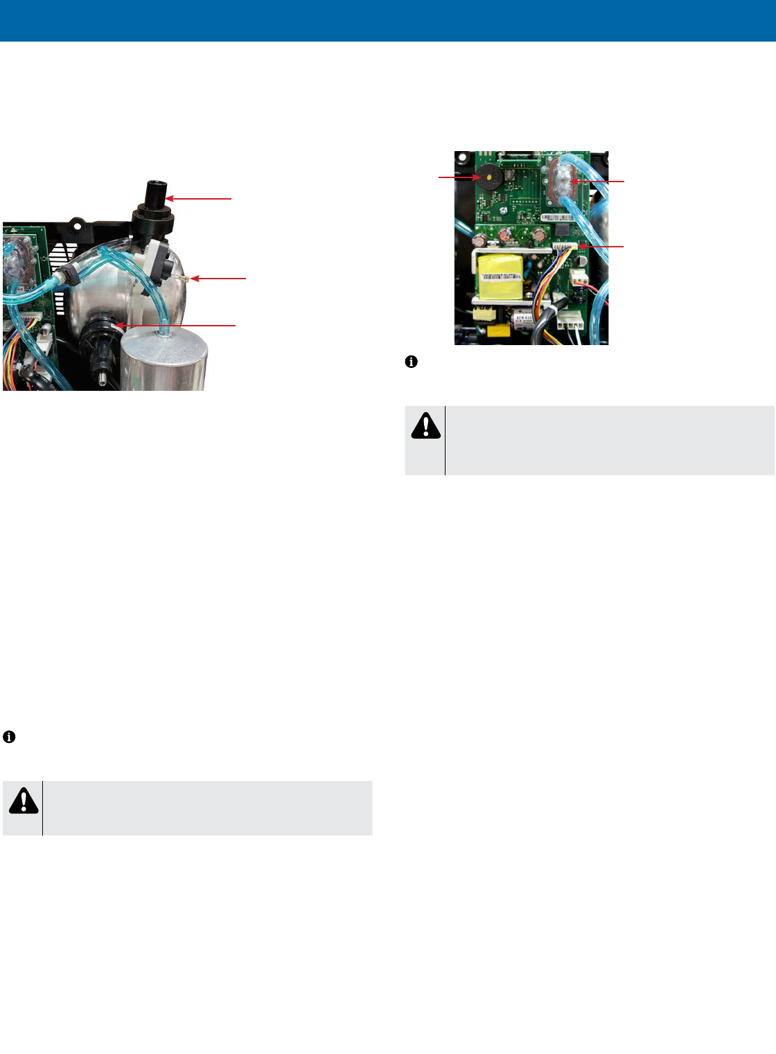
LT-2329
24
COMPONENT TESTING, REPAIR AND REPLACMENT
PRESSURE REGULATOR
The 1025 series has two pressure regulators. One regulates the outlet pressure
to the patient and the other regulates pressure to the auxiliary oxygen port. The
regulator located at the top of the accumulator tank is connected to the OSD and
stabilizes the ow of oxygen to the patient and establishes back pressure on the
system. It is pre-set at 20 ± 1 psi (137.8 ± 7 kPA) and should not have to be
adjusted in the eld.
Regulator for Auxillary
Oxygen Port
Pressure Test Point
Regulator for Outlet
Pressure to Patient
It is not necessary to test the pressure regulator unless there is a problem with
ow rate accuracy. The following test is only needed when troubleshooting ow
rate issues.
To test the pressure regulator:
1. Turn the unit “On.”
2. Set the ow meter at 2-3 lpm.
3. Attach a pressure gauge (part #PVO2D-601) to the oxygen outlet to obtain
a reference pressure. Use this reference pressure to determine if further
testing is needed.
4. If the reference pressure varies from the expected pressure by more than ±
1 psi or ± 7 kPa, connect a ‘T’ tting directly between the pressure regulator
tting and the pressure regulator tubing and attach the pressure gauge to
the 3rd leg of the ‘T’ tting. If the pressure reading is not within
20 ± 1 psi (137.8± 7 kPa), adjustment to the pressure regulator is required.
To adjust the pressure regulator:
1. If necessary, the pressure regulator can be adjusted by turning the allen
screw on top of the regulator until the pressure is within specication. Turn
clockwise to increase the pressure, and counterclockwise to decrease the
pressure.
NOTE– Before adjusting the pressure regulator, make sure no leaks exist by
using a certied leak detection solution such as Snoop® or equivalent (must not
contain ethylene glycol).
CAUTION
Do not apply leak test solution to any part of the rotary valve or the
main PC Board assembly.
A malfunction in the pressure regulator will cause either a loss or uctuation in
the oxygen ow which will be seen on the ow meter or a decrease in oxygen
concentration.
To replace the pressure regulator:
1. Make sure the unit is unplugged from the wall outlet.
2. Use the Cabinet Removal instructions listed previously to open the unit.
3. Remove the tubing clamp and tubing from the pressure regulator.
4. Unscrew the regulator from the accumulator tank.
5. Install a new regulator on the accumulator tank and attach the tubing and
tubing clamp.
PRINTED CIRCUIT BOARD
The printed circuit (PC) board is responsible for monitoring and controlling the
Drive DeVilbiss Oxygen Concentrator.
The PC board has preset alerts for low ow and power failure. Should any of the
alert values be exceeded, the patient alert system will activate.
Rotary Valve
Wire Harness
Alarm
OSD
NOTE– If the concentrator has been unused for an extended period, the unit
must run 20 minutes before the power fail alert will be enabled. This alert is
powered by a capacitor on the PC board.
CAUTION
Do not apply any force or ex to the PC Board when connecting or
disconnecting electronic or pneumatic components. Damage to the
electronic assembly is possible.
To remove and replace the PC board:
1. Make sure the unit is unplugged from the wall outlet.
2. Use the Cabinet Removal instructions listed previously to open the unit.
3. Disconnect all wires and electrical connectors.
4. Remove the 1/8" (3.2mm) tubing from both ttings on the oxygen sensor.
5. Remove the screw that secures the board to the unit and remove the PC
board.
6. Install the new PC board and secure it using the screw.
7. Reconnect all electrical wires, connectors and the tubing to the sensor.

25
LT-2329
COMPONENT TESTING, REPAIR AND REPLACMENT
ROTARY VALVE
The timed rotary valve alternately distributes pressure supplied by the
compressor to the sieve beds. While one bed is being pressurized the other bed
is being exhausted through the valve exhaust port.
The valve contains two revolving discs powered by a stepper motor to cycle the
pressure between the beds. DC voltage is supplied by the PC board to the motor
windings causing the internal discs to turn and direct pressure to the proper sieve
bed.
Rear View
Valve Wire Harness
Front View
Stepper Motor
If the rotary valve is not shifting properly, one bed may pressurize continuously;
the pressure building until the pressure relief valve on the compressor releases
the excess with a sputtering sound.
There are several reasons why the rotary valve could malfunction; therefore the
cause of failure must be determined before corrective action can be taken.
To test the rotary valve:
1. Use the Cabinet Removal instructions listed previously to open the unit for
testing.
2. Connect a pressure gauge to the test point on the accumulator tank to
observe unit cycling and the high and low bed pressures. Refer to the
section on Normal Operating Sequence and also Accumulator Pressure
Test.
a. If it is determined that the valve is shifting properly and the high and
low pressures are consistent, the valve is operating correctly.
b. If it is determined that the valve did not shift properly or the high
pressures or low pressures are uneven, check the valve wire harness
for any loose or broken connections. If harness connections are good,
then the problem is caused by either the rotary valve or PC board.
To replace the rotary valve:
1. Make sure the unit is unplugged from the wall outlet.
2. Use the Cabinet Removal instructions listed previously to open the unit.
3. Unplug valve wire harness from the valve.
4. Loosen clamps and remove bed hoses from each side of valve.
5. Loosen ladder clamps and remove pressure intake and exhaust hoses from
backside of valve, then remove valve.
6. Install the new rotary valve by reversing the above procedure.

LT-2329
26
FIGURES, DIAGRAMS AND PARTS LIST
1025 Unit with Auxiliary Oxygen Port
Rear View
Front Inside
40
25
13
3
11
6
35
47
8A-8B
5
7
39
37
2
20
36
1
42
12
49
9
46
38
Front View
33
IEC connector on
1025KS and
1025UK models only
41
28
24
44
48
31 (not shown)
30
Hour Meter
Visible Alerts
Purge Harness Assembly
Fixed Orifice
12
Check Valves
45
45A (valve cover
foam not shown)
Front Inside
(manifold version)
26
Accumulator Tank
(close-up)
42
26
1
41
50
51
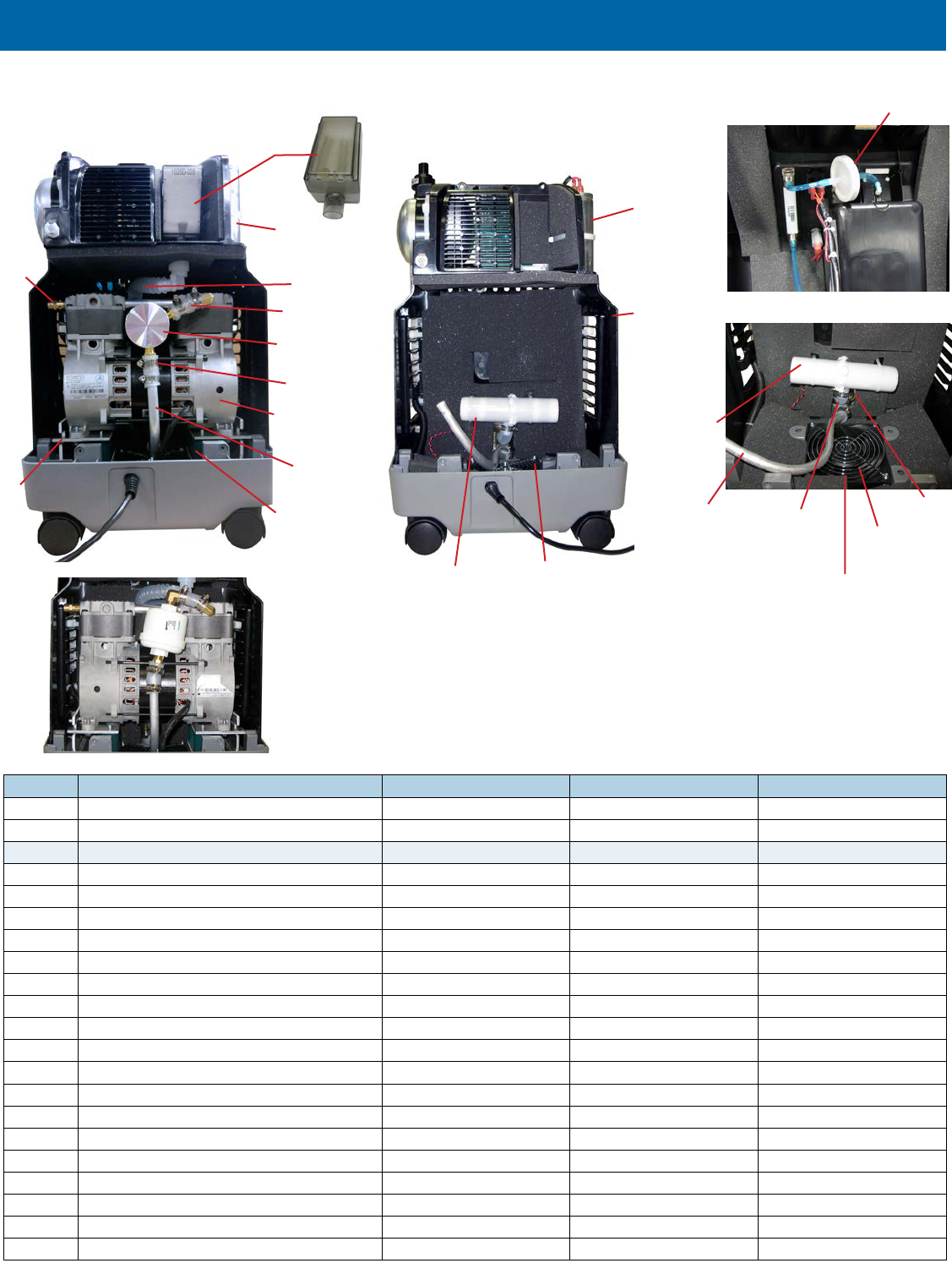
27
LT-2329
FIGURES, DIAGRAMS AND PARTS LIST
PART DESCRIPTION
1025DS 1025KS 1025UK
1 Accumulator Tank 1025D-610 1025D-610 1025D-610
2 Auxiliary Oxygen Port 525DD-635 525DD-635 525DD-635
Cabinet Parts:
3 Base 1025D-603 1025K-603 1025K-603
4 Compressor Box w/ Foam 1025D-615 1025D-615 1025D-615
5 Filter Door 525DD-639 525DD-639 525DD-639
6 Front Cover 525DD-611 525DD-611 525DD-611
7 Rear Cover 525DD-612 525DD-612 525DD-612
8A Cabinet Screw (Machine) 525DD-628 525DD-628 525DD-628
8B Cabinet Screw (Thread-forming) 525DD-636 525DD-636 525DD-636
9 Cable Tie (Large) 505DZ-617 505DZ-617 505DZ-617
10 Capacitor (Motor Start/Run) 1025DS-616 1025KS-616 1025UK-616
11 Caster, Non-locking 501DZ-603 501DZ-603 501DZ-603
12 Bed Check Valve PVO2D-607 PVO2D-607 PVO2D-607
13 Circuit Breaker 1025D-613 1025K-613 1025K-613
14 Cooling Fan 1025D-634 1025D-634 1025D-634
15 Cooling Fan Guard N/A N/A N/A
16 Compressor 1025D-625 1025K-625 1025K-625
17 Compressor Mounting Plate Package 1025D-632 1025D-632 1025D-632
18 Compressor Rebuild Kit 1025D-643 1025K-643 1025K-643
19 Exhaust Mufer 1025D-705 1025D-705 1025D-705
Rear Inside - Compressor Removed
1025 Unit with Auxiliary Oxygen Port
Behind Front Cover
23
19
10
14, 15
4
Rear Inside
21
22
27
16, 18 (not
shown)
34
30
29
43
17
10 (Location of
capacitor on
model 1025DS)
32
Inside Compressor Box
Exhaust
Muffler
Exhaust
Hose from
Rotary Valve
Heat
Exchange
Tube
Cooling Fan
& Guard
Rotary
Valve
10
(Location of capacitor on
models 1025KS and 1025UK)
Old style compressor
filter and connections
(no longer used)

LT-2329
28
FIGURES, DIAGRAMS AND PARTS LIST
ACCESSORIES
Carton with Shipping Inserts 1025D-606
Oxygen Outlet Connector - Plastic XM-1
Casters, Locking 525DS-603
Transll Caddy 525DD-650
Transll Hose PF1100TUB
High Flow (6-15 LPM) Bubble Humidier Salter Labs 7900 or equivalent
Low Flow (up to 6 LPM) Bubble Humidier Salter Labs 7600 or equivalent
High Flow Nasal Cannula Salter Labs 1600HF or
equivalent
TOOLS
Service Kit 444-501
Pressure Gauge PVO2D-601
Pressure Test Assembly 303DZ-637
Oxygen Analyzer (Max O
2
) R217P62
PART DESCRIPTION
1025DS 1025KS 1025UK
Filters:
20 Cabinet Air Filter 303DZ-605 303DZ-605 303DZ-605
21 Intake Bacteria Filter 1025D-605 1025D-605 1025D-605
22 Compressor Filter 1025D-682 1025D-682 1025D-682
23 Final Bacteria Filter PV5LD-651 PV5LD-651 PV5LD-651
Fittings:
24 Accumulator Tank "Tee" (not shown) 444-582 444-582 444-582
25 Flow Meter 1025D-607 1025D-607 1025D-607
26 Purge Manifold 1025D-618 1025D-618 1025D-618
27 Heat Exchanger Tube 1025D-655 1025D-655 1025D-655
Hoses:
28 1/8" ID (Blue) (4' Lg) 444-554 444-554 444-554
29 Compressor Intake Hose (Silicone) 1025D-657 1025D-657 1025D-657
30 1/2" ID Silicone Braided (2' LG) 505DZ-634 505DZ-634 505DZ-634
Hose Clamps:
31 Plastic (1/4" ID Hose) (not shown) N/A N/A N/A
32 Ladder Clamp (1/2" ID Hoses) 444-566 444-566 444-566
33 IEC Connector N/A N/A N/A
34 Motor Mounts 1025D-609 1025D-609 1025D-609
35 Oxygen Outlet Port 525DD-606 525DD-606 525DD-606
36 PC Board 1025D-622 1025D-622 1025D-622
37 Power Cord w/ Strain Relief PV5LD-618 VARIOUS VARIOUS
38 Power Cord Strap MC29D-657 MC29D-657 MC29D-657
39 Power Cord Strain Relief 505DZ-645 N/A N/A
40 Power Switch 1025D-508 1025D-508 1025D-508
41 Pressure Regulator (8.5 PSI) MC29D-612 MC29D-612 MC29D-612
42 Pressure Regulator (20 PSI) 1025D-612 1025D-612 1025D-612
43 Pressure Relief Valve 1025D-614 1025D-614 1025D-614
44 Purge Harness Assembly 1025D-617 1025D-617 1025D-617
45 Rotary Valve 515ADZ-702 515ADZ-702 515ADZ-702
45A Valve Cover Foam 525DD-642 525DD-642 525DD-642
46 Sieve Bed 1025D-619 1025D-619 1025D-619
47 Top Cover Label 1025D-631 1025D-631 1025D-631
Wire Harness:
48 Main Harness 1025D-623 1025K-623 1025K-623
49 Rotary Valve Harness 525D-621 525D-621 525D-621
50 Front Label 1025D-627 1025D-627 1025D-627
51 Rating Label 1025DS-633 1025KS-633 1025UK-633

29
LT-2329
FIGURES, DIAGRAMS AND PARTS LIST
Pneumatic Diagram

LT-2329
30
FIGURES, DIAGRAMS AND PARTS LIST
COMPRESSOR
FOR MODELS NOT EQUIPPED WITH A THERMOSTAT
FOR MODELS EQUIPPED WITH A THERMOSTAT
BROWN
BLUE
INLET
APPLIANCE
FOR 230 VOLT UNITS
BROWN
BLACK
WHITE
BLACK
COMPRESSOR
BLACK
WHITE
OR BLUE
BROWN
WHITE OR BLUE
BLACK
BLUE
BLUE
WHITE OR BLUE
P3-2
P3-4
J4-1
J4-3
FOR 115 VOLT UNITS
RED
CIRCUIT BREAKER
SWITCH
ELECTRONIC
CONTROLS
BOARD
RED
J3-2
J3-1
J2-4to9
J2-1to3
MOTOR RUN
CAPACITOR
RED
RED
RED
RED
MOTOR RUN
CAPACITOR
FAN
DC VALVE MOTOR
VALVE SENSOR
Wiring Diagram

31
LT-2329
ORDERING INFORMATION AND PARTS RETURN
ORDERING INFORMATION
When ordering components, instruction guides, or service manuals the following must be provided:
• Unit Catalog Number
• Unit Serial Number
• Part Number
• Quantity Required
DeVilbiss Concentrator 10 Liter Series Instruction Guide:
• A-1025 1025DS, 1025KS & 1025UK English, Spanish, French
• SE-1025-1 1025DS, 1025KS & 1025UK English, Spanish, French, German, Italian, Dutch, Turkish, Portuguese, Polish
• SE-1025-2 1025DS, 1025KS & 1025UK English, Greek, Danish, Swedish, Finnish, Norweigan, Czech, Slovak, Chinese (simplied)
DeVilbiss Concentrator 10 Liter Series Service Manual:
• LT-2329 1025DS, 1025KS & 1025UK English
DeVilbiss Oxygen Concentrator Service Log:
• A-1007 All English
• A-1007-PT All Portuguese
• A-1007-DE All German
Orders may be placed by calling:
• Customer Service 800-338-1988
• International Department 814-443-4881
• Europe +49 (0) 621-178-98-0
RETURNS
Before returning units to the factory, call the Drive DeVilbiss Healthcare Customer Service Department (800-338-1988) or (814-443-4881) to obtain a return authorization
number. Include in the package a note indicating the return authorization number along with your company name, address, phone number, and account number. The
return authorization number should also be written on the outside of the package.
To expedite your order for non-warranty parts, the following information should be given to the representative:
• Catalog number
• Serial number
• Hour meter reading for each concentrator
• Account number
• Company name and address
• Description of problem

LT-2329
32
WARRANTY
WARRANTY
Drive DeVilbiss Healthcare warrants the Drive DeVilbiss 10 Liter Oxygen Concentrator under the conditions and limitations stated below. Drive DeVilbiss warrants this
equipment to be free from defects in workmanship and materials for three (3) years from date of factory shipment to the original purchaser, (typically the healthcare
provider) unless contractually specied otherwise. This warranty is limited to the Buyer of new equipment purchased directly from Drive DeVilbiss, or one of its Providers,
Distributors, or Agents. Drive DeVilbiss’ obligation under this warranty is limited to product repair (parts and labor) at its factory or at an Authorized Service Center.
Routine maintenance items, such as lters, are not covered under this warranty, nor does it cover normal wear and tear.
Warranty Claims Submissions
The original purchaser must submit any warranty claim to Drive DeVilbiss or to an Authorized Service Center. Upon verication of the warranty status, instructions will be
issued. For all returns, the original purchaser must (1) properly package the unit in a DeVilbiss approved shipping container, (2) properly identify the claim with the Return
Authorization Number, and (3) send the shipment freight prepaid. Service under this warranty must be performed by Drive DeVilbiss and/or an Authorized Service Center.
NOTE– This warranty does not obligate Drive DeVilbiss to provide a loaner unit during the time that an oxygen concentrator is undergoing repair.
NOTE– Replacement components are warranted for the unexpired portion of the original Limited Warranty.
This warranty shall be voided, and Drive DeVilbiss shall be relieved of any obligation or liability if:
• The device has been misused, abused, tampered with, or used improperly during this period.
• Malfunction results from inadequate cleaning or failure to follow the instructions.
• The equipment is operated or maintained outside the parameters indicated in the Drive DeVilbiss operating and service instructions.
• Unqualied service personnel conduct routine maintenance or servicing.
• Unauthorized parts or components (i.e., regenerated sieve material) are used to repair or alter the equipment.
• Unapproved lters are used with the unit.
THERE IS NO OTHER EXPRESS WARRANTY. IMPLIED WARRANTIES, INCLUDING THOSE OF MERCHANTABILITY AND FITNESS FOR A PARTICULAR
PURPOSE, ARE LIMITED TO THE DURATION OF THE EXPRESS LIMITED WARRANTY AND TO THE EXTENT PERMITTED BY LAW ANY AND ALL IMPLIED
WARRANTIES ARE EXCLUDED. THIS IS THE EXCLUSIVE REMEDY AND LIABILITY FOR CONSEQUENTIAL AND INCIDENTAL DAMAGES UNDER ANY AND ALL
WARRANTIES ARE EXCLUDED TO THE EXTENT EXCLUSION IS PERMITTED BY LAW. SOME STATES DO NOT ALLOW LIMITATIONS ON HOW LONG AN
IMPLIED WARRANTY LASTS, OR THE LIMITATION OR EXCLUSION OF CONSEQUENTIAL OR INCIDENTAL DAMAGES, SO THE ABOVE LIMITATION OR
EXCLUSION MAY NOT APPLY TO YOU.
This warranty gives you specic legal rights, and you may also have other rights that vary from state to state.
NOTE– International warranties may vary.
Ordering and Returning Parts
Drive DeVilbiss Customer Service Contact Information
Customer Service (USA): 877-224-0946
International Department: [email protected]
Ordering Non-Warranty Replacement Parts
Order non-warranty parts and literature from your Drive DeVilbiss provider. To expedite the process, be prepared to provide the following information:
• Account and ship-to numbers
• Ship-to address
• Part numbers and/or descriptions
• Quantity required
• Unit catalog number
• Unit serial number
• Hours of operation
Return and Disposal
This device may not be disposed of with household waste. After use of the device, please return the device to the provider for disposal. This device contains electrical
and/or electronic components that must be recycled per EU Directive 2012/19/EU-Waste Electrical and Electronic Equipment (WEEE). Non-infectious used accessories
(e.g. nasal cannula) can be disposed of as residential waste. The disposal of infectious accessories (e.g. nasal cannula from an infected user) must be made via an
approved waste disposal company. Names and addresses can be obtained from the local municipality.

33
LT-2329
SPECIFICATIONS
DEVILBISS 10-LITER SERIES
Catalog Number 1025DS 1025KS
1025UK
Delivery Rate 2 to 10 LPM 2 to 10 LPM 2 to 10 LPM
Maximum Recommended Flow (@
nominal outlet pressures of zero and
7 kPa)**
10 LPM 10 LPM 10 LPM
Outlet Pressure 20.0 ± 1.0 psi (138 kPa +/- 7 kPa) 20.0 ± 1.0 psi (138 kPa +/- 7 kPa) 20.0 ± 1.0 psi (138 kPa +/- 7 kPa)
Auxiliary Oxygen Port **
Outlet Pressure: <15 psi
Outlet Flow: 2 LPM
Outlet Pressure: <15 psi
Outlet Flow: 2 LPM
Outlet Pressure: <15 psi
Outlet Flow: 2 LPM
Electrical Rating 120 V, 60 Hz, 6.1 Amp 230 V~, 50 Hz, 3.2 Amp 240 V~, 50 Hz, 3.2 Amp
Operating Voltage Range 102-132 V~, 60 Hz 195-253 V~, 50 Hz 204-264 V~, 50 Hz
Oxygen Percentage 2-10 LPM=87%-96% 2-10 LPM=93% +3%/-6% 2-10 LPM=93% +3%/-6%
Operating Altitude
(tested at 70˚F {21˚C} only)
0-1500 M (0-5000 ft)
Across the voltage range:
No degradation of performance
Across the voltage range:
No degradation of performance
Across the voltage range:
No degradation of performance
Operating Environment Range*
41˚F (5˚C) to 95˚F (35˚C), humidity
range of 15% to 93% non-condensing
No degradation in performance across the
operating voltage range.
No degradation in performance across the
operating voltage range.
No degradation in performance across the
operating voltage range.
Power Consumption 120 vac, 60HZ: 639 watts average 230 vac, 50Hz: 664 watts average 240 vac, 50Hz: 670 watts average
Weight 42 lbs. (19 Kilograms) 42 lbs. (19 Kilograms) 42 lbs. (19 Kilograms)
Safe Working Load 53 lbs. (24 Kilograms) 53 lbs. (24 Kilograms) 53 lbs. (24 Kilograms)
Sound Pressure Level at 3 and 10LPM <59 dBA <57 dBA <57 dBA
Sound Power Level at 3 and 10 LPM <69 dBA <67 dBA <67 dBA
Dimensions
24.5”H x 13.5”W x 12”D
(62.2 x 34.2 x 30.4 cm)
24.5”H x 13.5”W x 12”D
(62.2 x 34.2 x 30.4 cm)
24.5”H x 13.5”W x 12”D
(62.2 x 34.2 x 30.4 cm)
Maximum Limited Pressure 35 PSIG (241 kPa) 35 PSIG (241 kPa) 35 PSIG (241 kPa)
Operating System Time Cycle / Pressure Swing Time Cycle / Pressure Swing Time Cycle / Pressure Swing
Low Oxygen Indicator
<82% low oxygen
<60% very low oxygen
<82% low oxygen
<60% very low oxygen
<82% low oxygen
<60% very low oxygen
Storage Conditions -13˚F (-25˚C) to 158˚F (70˚C), humidity range of
15% to 93% non-condensing
-13˚F (-25˚C) to 158˚F (70˚C), humidity range
of 15% to 93% non-condensing
-13˚F (-25˚C) to 158˚F (70˚C), humidity range
of 15% to 93% non-condensing
Equipment Class and Type
Class II Equipment Double Insulated;
Type B Applied Part
Ordinary Equipment, IP21
Class II Equipment Double Insulated;
Type B Applied Part
IP21
Class II Equipment Double Insulated;
Type B Applied Part
IP21
Approval Body and Safety Standard
TUV
ANSI/AAMI ES60601-1:2005+A2 (R2012) +A1
IEC 60601-1-6:2010
IEC 60601-1-11:2015
ISO 80601-2-69:2014
CAN/CSA-C22.2 No. 60601-1:14
CAN/CSA-C22.2 No. 60601-1-6:11
CAN/CSA-C22.2 No. 60601-1-11:15
CAN/CSA-C22.2 No. 80601-2-69:16
TUV
IEC 60601-1:2012
IEC 60601-1-6:2010+A1
IEC 60601-1-11:2015
EN ISO 80601-2-69:2014
TUV
IEC 60601-1:2012
IEC 60601-1-6:2010+A1
IEC 60601-1-11:2015
EN ISO 80601-2-69:2014
CE mark No Yes Yes
EMC Compliance To EN60601-1-2 EN60601-1-2 EN60601-1-2
* NOTE– The OSD performance at 41˚F (5˚C) to 95˚F (35˚C), 93% R.H. through voltage range on the 1025 veried at 670m.
**The maximum recommended ow is 6 LPM when an oxygen bottle is being lled with oxygen from the auxiliary oxygen port.
Specications subject to change without notice.
Oxygen Concentration vs Flow Rate
Flow L/m %O
2
10 87% - 92%
9 87% - 93%
8 87% - 95%
7 87% - 96%
6 87% - 96%
5 87% - 96%
4 87% - 95%
3 87% - 95%
2 87% - 94%

LT-2329
34
ELECTROMAGNETIC COMPATIBILITY INFORMATION
ELECTROMAGNETIC COMPATIBILITY INFORMATION
WARNING
MR Unsafe
Do not bring the device or accessories into a Magnetic Resonance (MR) environment as it may cause unacceptable risk to the patient or damage to the
oxygen concentrator or MR medical devices. The device and accessories have not been evaluated for safety in an MR environment.
Do not use the device or accessories in an environment with electromagnetic equipment such as CT scanners, Diathermy, RFID and electromagnetic security
systems (metal detectors) as it may cause unacceptable risk to the patient or damage to the oxygen concentrator. Some electromagnetic sources may not be
apparent, if you notice any unexplained changes in the performance of this device, if it is making unusual or harsh sounds, disconnect the power cord and
discontinue use. Contact your home care provider.
This device is suitable for use in home and healthcare environments except for near active HF SURGICAL EQUIPMENT and the RF shielded room of an ME
SYSTEM for magnetic resonance imaging, where the intensity of Electromagnetic DISTURBANCES is high.
WARNING
Use of this equipment adjacent to or stacked with other equipment should be avoided because it could result in improper operation. If such use is necessary,
this equipment and the other equipment should be observed to verify that they are operating normally.
WARNING
Portable RF communications equipment (including peripherals such as antenna cables and external antennas) should be used no closer than 30 cm (12
inches) to any part of the oxygen concentrator, including cables specied by the manufacturer. Otherwise, degradation of the performance of this equipment
could result.
Electromagnetic Compatibility
TEST DESCRIPTION SPECIFICATION NOTES RESULTS
CISPR11 & IEC 60601-1-2:2014 (4TH EDITION)
RF Emissions CISPR 11 Group 1 Complies
RF Emissions CISPR 11 Class B Complies
Harmonic Current Emissions EN 61000-3-2:2014 AC Input Complies
Voltage Fluctuations & Flicker EN 61000-3-3:2013 AC Input Complies
Electrostatic Discharge Immunity EN 61000-4-2:2008 ±15kV (Air)
8kV (Contact)
Complies
Radiated Electromagnetic Field Immunity EN 61000-4-3:2006 80MHz to 2.7GHz @ 10V/m; 80% AM at 1kHz Complies
Fast Transient/Burst Immunity EN 61000-4-4:2004 ±2kV for Power Lines & ±1kV for I/O Lines Complies
Surge Immunity EN 61000-4-5:2006 ±1kV differential
±2kV common
Complies
Conducted RF Immunity EN 61000-4-6:2009 3Vrms 150kHz to 80MHz
6Vrms ISM Band frequencies between 150kHz-80MHz
Complies
Magnetic Field Immunity EN 61000-4-8:2010 30A/m Complies
Voltage Dips, Short Interruptions & Variations EN 61000-4-11:2004 100% dip 0.5 cycle
100% dip 1 cycles
30% dip 25 cycles
100% dip 5 sec
Complies

DeVilbiss Healthcare LLC • 100 DeVilbiss Drive • Somerset, PA 15501 • USA
800-338-1988 • 814-443-4881 • www.DeVilbissHealthcare.com
© 2020 DeVilbiss Healthcare LLC. 08.20 All Rights Reserved. LT-2329 Rev D
DeVilbiss
®
and OSD
®
are registered trademarks of DeVilbiss Healthcare. Teon
®
is a registered trademark of DuPont. Snoop
®
is a
registered trademark of SWAGELOK
0044
DeVilbiss Healthcare LLC
100 DeVilbiss Drive
Somerset, PA 15501-2125
USA
800-338-1988 • 814-443-4881
Drive DeVilbiss Healthcare Ltd.
Heathfield Lane
Birkenshaw
West Yorkshire BD11 2HW
ENGLAND
+44 (0) 845 0600 333
Drive DeVilbiss Australia Pty Limited
Building F, 2 Hudson Ave
Castle Hill, NSW 2154
AUSTRALIA
+61 02 9899 3144
Drive DeVilbiss Healthcare France
Chaussée du Ban la Dame
Parc d’activités Eiffel Energie
ZAC du Ban la Dame - BP 19
54390 Frouard
FRANCE
+33 (0) 3 83 495 495
DeVilbiss Healthcare GmbH
Kamenzer Straße 3
68309 Mannheim
GERMANY
+49 (0) 621-178-98-0
