
.
The Gerber Layer Format
Specification
A format developed by Ucamco
Revision 2021.02

Copyright Ucamco NV 2
Having a question or remark about the spec? Please contact us at gerber@ucamco.com
Contents
Contents ........................................................................................................................ 2
Preface ........................................................................................................................... 7
1 Introduction .............................................................................................................. 8
1.1 Scope and Target Audience ................................................................................ 8
1.2 Further Resources .............................................................................................. 8
1.3 Reference Gerber Viewer ................................................................................... 8
1.4 Copyright and Intellectual Property ..................................................................... 9
2 Overview ................................................................................................................. 10
2.1 File Structure ..................................................................................................... 10
2.2 Apertures ........................................................................................................... 10
2.3 Graphical objects .............................................................................................. 11
2.4 Draws and Arcs ................................................................................................. 12
2.5 Operations (D01, D02, D03) ............................................................................. 13
2.6 Graphics State .................................................................................................. 14
2.7 Polarity .............................................................................................................. 16
2.8 Blocks ................................................................................................................ 17
2.9 Attributes ........................................................................................................... 17
2.10 Commands Overview ..................................................................................... 18
2.11 Processing a Gerber File ................................................................................ 19
2.12 Glossary .......................................................................................................... 21
2.13 Annotated Example Files ................................................................................ 24
Example: Two Square Boxes ................................................................... 24
Example: Polarities and Apertures ........................................................... 26
2.14
Conformance .................................................................................................. 30
3 Syntax ..................................................................................................................... 31
3.1 Character Set .................................................................................................... 31
3.2 Grammar Syntax ............................................................................................... 31
3.3 Commands ........................................................................................................ 33
3.4 Data Types ........................................................................................................ 35
Integers ...................................................................................................... 35
Decimals ..................................................................................................... 35
Strings ........................................................................................................ 35
Fields .......................................................................................................... 36
Names ........................................................................................................ 36
3.5
Full Grammar of the Gerber Format .................................................................. 37

Copyright Ucamco NV 3
Having a question or remark about the spec? Please contact us at gerber@ucamco.com
3.6 File Extension, MIME Type and UTI ................................................................. 43
4 Graphics.................................................................................................................. 44
4.1 Comment (G04) ................................................................................................ 44
4.2 Coordinate Commands ..................................................................................... 45
Unit (MO) .................................................................................................... 45
Format Specification (FS) ........................................................................... 46
4.3
Aperture Definition (AD) .................................................................................... 47
AD Command ............................................................................................. 47
Zero-size Apertures .................................................................................... 48
Examples .................................................................................................... 48
4.4
Standard Aperture Templates ........................................................................... 49
Overview..................................................................................................... 49
Circle .......................................................................................................... 49
Rectangle ................................................................................................... 51
Obround ..................................................................................................... 52
Polygon ...................................................................................................... 53
Transparency of Holes ............................................................................... 54
4.5
Aperture Macro (AM) ......................................................................................... 55
Primitives .................................................................................................... 57
Exposure Parameter................................................................................... 66
Rotation Parameter .................................................................................... 67
Macro Variables and Expressions .............................................................. 68
Examples .................................................................................................... 69
4.6
Set Current Aperture (Dnn) ............................................................................... 73
4.7 Interpolation State Commands (G01,G02,G03,G75) ........................................ 74
Linear Interpolation (G01)........................................................................... 74
Circular Interpolation (G02, G03, G75) ....................................................... 75
4.8
Operations (D01/D02/D03) ............................................................................... 79
Overview..................................................................................................... 79
Interpolate (D01)......................................................................................... 81
Move (D02) ................................................................................................. 81
Flash (D03) ................................................................................................. 81
Example ..................................................................................................... 82
4.9
Aperture Transformations (LP, LM, LR, LS) ...................................................... 83
Overview..................................................................................................... 83
Load Polarity (LP) ....................................................................................... 85
Load Mirroring (LM) .................................................................................... 85
Load Rotation (LR) ..................................................................................... 85
Load Scaling (LS) ....................................................................................... 86
Examples .................................................................................................... 86
4.10
Region Statement (G36/G37) ......................................................................... 89
Region Overview ...................................................................................... 89
Region Statement Syntax ......................................................................... 90

Copyright Ucamco NV 4
Having a question or remark about the spec? Please contact us at gerber@ucamco.com
Valid Contours .......................................................................................... 90
Examples .................................................................................................. 92
Power and Ground Planes ..................................................................... 108
4.11
Block Aperture (AB) ...................................................................................... 111
Overview of block apertures ................................................................... 111
AB Statement Syntax ............................................................................. 111
Usage of Block Apertures ....................................................................... 112
Example ................................................................................................. 113
4.12
Step and Repeat (SR) .................................................................................. 115
4.13 End-of-file (M02) ........................................................................................... 118
4.14 Numerical Accuracy ...................................................................................... 119
Visualization ........................................................................................... 119
Image Processing ................................................................................... 119
5 A
ttributes .............................................................................................................. 121
5.1 Attributes Overview ......................................................................................... 121
5.2 File Attributes (TF) .......................................................................................... 123
5.3 Aperture Attributes (TA) .................................................................................. 123
Aperture Attributes on Regions ................................................................ 124
5.4
Object Attributes (TO) ..................................................................................... 124
5.5 Delete Attribute (TD) ....................................................................................... 125
5.6 Standard Attributes ......................................................................................... 126
Overview................................................................................................... 126
.Part .......................................................................................................... 128
.FileFunction ............................................................................................. 129
.FilePolarity ............................................................................................... 133
.SameCoordinates .................................................................................... 134
.CreationDate ........................................................................................... 134
.GenerationSoftware................................................................................. 135
.ProjectId .................................................................................................. 135
.MD5 ......................................................................................................... 136
.AperFunction ......................................................................................... 138
.DrillTolerance ........................................................................................ 148
.FlashText ............................................................................................... 148
.N (Net) ................................................................................................... 149
.P (Pin) ................................................................................................... 151
.C (Component) ...................................................................................... 153
5.7
Text in the Image ............................................................................................ 154
5.8 Examples ........................................................................................................ 155
6 PCB Fabrication and Assembly Data ................................................................. 157
6.1 Structure .......................................................................................................... 157
6.2 Mandatory Attributes ....................................................................................... 157

Copyright Ucamco NV 5
Having a question or remark about the spec? Please contact us at gerber@ucamco.com
6.3 Alignment ........................................................................................................ 157
6.4 Pads ................................................................................................................ 157
6.5 The Profile ....................................................................................................... 157
6.6 Drill/rout files ................................................................................................... 158
6.7 Drawings and Data .......................................................................................... 162
6.8 The CAD Netlist .............................................................................................. 162
6.9 PCB Assembly Data .................................................. 165
7 Errors and Bad Practices .................................................................................... 168
7.1 Errors .............................................................................................................. 168
7.2 Bad Practices .................................................................................................. 171
8 Deprecated Format Elements ............................................................................. 173
8.1 Deprecated Commands .................................................................................. 173
Overview................................................................................................... 173
Axis Select (AS)........................................................................................ 174
Image Name (IN) ...................................................................................... 175
Image Polarity (IP) .................................................................................... 175
Image Rotation (IR) .................................................................................. 176
Load Name (LN) ....................................................................................... 177
Mirror Image (MI) ...................................................................................... 177
Offset (OF) ............................................................................................... 178
Scale Factor (SF) ..................................................................................... 179
Single-quadrant arc mode (G74) ............................................................ 181
8.2 D
eprecated Command Options ....................................................................... 185
Format Specification (FS) Options ........................................................... 185
Rectangular Hole in Standard Apertures .................................................. 186
Draws and Arcs with Rectangular Apertures ............................................ 187
Macro Primitive Code 2, Vector Line ........................................................ 188
Macro Primitive Code 22, Lower Left Line ................................................ 188
Macro Primitive Code 6, Moiré ................................................................. 189
8.3 D
eprecated Syntax Variations ......................................................................... 190
Combining G01/G02/G03 and D01 in a single command. ....................... 190
Coordinate Data without Operation Code ................................................. 191
Style Variations in Command Codes ........................................................ 191
Deprecated usage of SR .......................................................................... 191
8.4 D
eprecated Attribute Values ........................................................................... 191
8.5 Standard Gerber (RS-274-D) .......................................................................... 193

Copyright Ucamco NV 6
Having a question or remark about the spec? Please contact us at gerber@ucamco.com
9 References ............................................................................................................ 194
10 History ................................................................................................................... 195
11 Revisions .............................................................................................................. 197
11.1 Revision 2021.02 .......................................................................................... 197
11.2 Revision 2020.09 – X3 .................................................................................. 197
11.3 Revision 2019.09 .......................................................................................... 197
11.4 Revision 2019.06 .......................................................................................... 197
11.5 Revision 2018.11 .......................................................................................... 198
11.6 Revision 2018.09 .......................................................................................... 198
11.7 Revision 2018.06 .......................................................................................... 198
11.8 Revision 2018.05 .......................................................................................... 198
11.9 Revision 2017.11 .......................................................................................... 198
11.10 Revision 2017.05 .......................................................................................... 199
11.11 Revision 2017.03 .......................................................................................... 199
11.12 Revision 2016.12 – Nested step and repeat ................................................. 199
11.13 Revision 2016.11 .......................................................................................... 199
11.14 Revision 2016.09 .......................................................................................... 200
11.15 Revision 2016.06 .......................................................................................... 200
11.16 Revision 2016.04 .......................................................................................... 200
11.17 Revision 2016.01 .......................................................................................... 200
11.18 Revision 2015.10 .......................................................................................... 201
11.19 Revision 2015.07 .......................................................................................... 201
11.20 Revision 2015.06 .......................................................................................... 201
11.21 Revision J3 (2014 10) ................................................................................... 201
11.22 Revision J4 (2015 02) ................................................................................... 201
11.23 Revision J2 (2014 07) ................................................................................... 201
11.24 Revision J1 (2014 02) – X2 .......................................................................... 202
11.25 Revision I4 (2013 10) .................................................................................... 202
11.26
Revision I3 (2013 06) .................................................................................... 202
11.27 Revision I2 (2013 04) .................................................................................... 202
11.28 Revision I1 (2012 12) .................................................................................... 202

Copyright Ucamco NV 7
Having a question or remark about the spec? Please contact us at gerber@ucamco.com
Preface
The Gerber format is the de facto open standard for printed circuit board (PCB) design data
transfer. As an UTF-8 human-readable format Gerber is portable and easy to debug. It is
compact and unequivocal, and simple - there are just 27 commands. Every PCB design system
outputs Gerber files and every PCB fabrication software inputs them. Implementations are
thoroughly field-tested. Gerber's widespread availability allows PCB professionals to exchange
PCB design data securely and efficiently. It has been called “the backbone of the electronics
fabrication industry”.
Gerber is at its core is an open vector format for 2D binary images specifying PCB copper
layers, solder mask, legend, etc. Attributes transfer meta-information with the images. Attributes
are akin to labels expressing, for example, that an image represents the top solder mask, or that
a pad stack is a via or component stack, and which components are positioned where.
Attributes transfer the meta-information necessary for fabrication and assembly. A set of well-
constructed Gerber files reliably and productively transfers PCB fabrication from design to
fabrication, and component information to assembly.
Although other data formats have appeared, they have not displaced Gerber. The reason is
simple. Any problems in PCB fabrication data transfer are not due to limitations in the Gerber
format but are due to poor practices and poor implementations. The new formats are more
complicated and less transparent. To quote Günther Schindler: "“There are no superfluous,
production-specific attributes like in other CAM formats. Gerber X2 is simple and tidy.” Poor
practices and poor implementations in unfamiliar, new and complicated formats are more
damaging than in a well-known, well-tested and simple format. The industry has not adopted
new formats. Gerber remains the standard.
Ucamco continuously clarifies this document and adapts it to current needs based on input from
the user community. Ucamco thanks the individuals that help us with comments, criticism, and
suggestions.
The Gerber format was named after Joseph Gerber, who fled his native Austria from the Nazis,
and arrived in the USA as a teenager, alone and penniless. With his technical genius and work
ethic he became a very successful inventor and technical entrepreneur. The American dream
come true. Mr. Gerber pioneered photoplotting in PCB fabrication, which is the link with the
format. Ucamco is honored to look after a format called after this brilliant man.
The emergence of Gerber as a standard for PCB fabrication data is the result of efforts by many
individuals who developed outstanding software for Gerber files. Without their dedication there
would be no standard format in the electronics fabrication industry. Ucamco thanks these
dedicated individuals.
Karel Tavernier
Managing Director,
Ucamco

Copyright Ucamco NV 8
Having a question or remark about the spec? Please contact us at gerber@ucamco.com
1 Introduction
1.1 Scope and Target Audience
This document specifies the Gerber layer format, an UTF-8 format for representing PCB
fabrication data. The Gerber format is the de facto standard in the printed circuit board (PCB).
This specification is intended for developers and users of Gerber software. A basic knowledge
of PCB design or fabrication is assumed, and knowledge about PCB CAD/CAM is helpful.
1.2 Further Resources
The Ucamco website contains articles about the use of the Gerber format as well as sample
files. For more information about Gerber or Ucamco see www.ucamco.com
, or mail to
Ucamco strives to make this specification easy to read and unequivocal. If you find a part of this
specification unclear, please ask. Your question will be answered, and it will be considered to
improve this document. We are grateful for any suggestion for improvement.
1.3 Reference Gerber Viewer
Ucamco provides a reference Gerber file viewer - free of charge – at gerber-viewer.ucamco.com.
The Reference Gerber Viewer provides an easy-to-use reference for both X1 and X2 Gerber
files. - the utmost care was taken to display valid Gerber files correctly. It gives a clear warning
on risky errors. It is a convenient complement to the written specification. (The specification has
precedence if it conflicts with the viewer.)
The Reference Gerber Viewer is an easy tool to review PCB fabrication data. For completeness,
it also displays drill files in NC format and netlists in IPC-D-356 files. If X2 is used the layer
structure is displayed, and the function of all objects can be checked – e.g. whether a drill hole is
a via or a component hole.
As the Reference Gerber Viewer is a cloud-based on-line web service there is no software to
download, install and maintain –it is always up to date. It is simple and easy to learn. It offers the
following benefits:
• For developers, it provides an easy way to test their Gerber output and to answer
questions about the interpretation of the specification.
• For users of Gerber files, it provides an easy way to check the file they have received or
are about to send, and to settle discussions about the interpretation of a file.
It is allowed to integrate a link to the online reference viewer in your website. Email us a
for more information.

Copyright Ucamco NV 9
Having a question or remark about the spec? Please contact us at gerber@ucamco.com
1.4 Copyright and Intellectual Property
© Copyright Ucamco NV, Gent, Belgium
Ucamco owns copyrights in this document. All rights reserved. No part of this document or its
content may be re-distributed, reproduced or published, modified or not, translated or not, in any
form or in any way, electronically, mechanically, by print or any other means without prior written
permission from Ucamco. One reason Ucamco must retain its copyrights in the Gerber Format®
specification is to maintain the integrity of the standard.
The information contained herein is subject to change without prior notice. Revisions may be
issued from time to time. This document supersedes all previous versions. Users of the Gerber
Format
®
, especially software developers, must consult www.ucamco.com to determine whether
new revisions were issued.
Ucamco developed the Gerber Format
®
. All intellectual property contained in it is solely owned
by Ucamco. By publishing this document Ucamco has not granted any license or alienated any
rights to the intellectual property contained in it. To use this intellectual property, developers of
software interfaces based on this format specification must make a reasonable effort to comply
with the latest revision of the specification; this is necessary to maintain the integrity of the
standard.
Gerber Format
®
is a Ucamco registered trademark. By using this document, developing
software interfaces based on this format or with the name Gerber Format
®
, users agree not to (i)
rename the Gerber Format
®
; (ii) associate the Gerber Format
®
with data that does not conform
to the Gerber format specification; (iii) develop derivative versions, modifications or extensions
without prior written approval by Ucamco; (iv) make alternative interpretations of the data; (v)
communicate that the Gerber Format
®
is not owned by Ucamco, explicitly or implied.
The material, information and instructions are provided AS IS without warranty of any kind,
either express or implied. Ucamco does not warrant, or makes any representations regarding,
the use of the information contained herein, the results of its use, non-infringement,
merchantability, or fitness for a particular purpose . Ucamco shall not be liable for any direct,
indirect, consequential, or incidental damages arising out of the use or inability to use the
information contained herein. You are solely responsible for determining the appropriateness of
using this information and assume any risks associated with it.
All product names cited are trademarks or registered trademarks of their respective owners.

Copyright Ucamco NV 10
Having a question or remark about the spec? Please contact us at gerber@ucamco.com
2 Overview
2.1 File Structure
The Gerber layer format is a 2D bi-level vector image format: the image is defined by resolution-
independent graphical objects. Bi-level or binary images in each point take one of two possible
values, typically labeled black and white.
A single Gerber file specifies a single image. A Gerber file is complete: it does not need sidecar
files or external parameters to be interpreted. One Gerber file represents one image. One image
needs one file only.
A Gerber file is a stream of commands. The commands create a stream of graphical objects
(see 2.2) that are put on the image plane in order to create the final image. Other commands
add attributes to those objects or to the overall file. Attributes are akin to label that add meta
information to the objects without affecting the image.
The commands are ordered. A Gerber file can be processed in a single pass. Names,
parameters and objects must be defined before they are used.
A Gerber file uses printable 7-bit ASCII characters for all commands and names defined in the
specification – this fully covers image generation. For attribute values the complete UTF-8
encoding is allowed, as they can be human defined. This makes the files printable and human
readable.
Below is a small example Gerber file that creates a circle of 1.5 mm diameter centered on the
origin. There is one command per line.
%FSLAX26Y26*%
%MOMM*%
%ADD100C,1.5*%
D100*
X0Y0D03*
M02*
2.2 Apertures
An aperture is a 2D plane figure. Aperture typically have simple shapes, as in the examples
below, but complex shapes can be created.
Apertures are the basic tools to create graphic images in the plane. They can be replicated in
the plane, optionally rotated, mirrored, and scaled. This replication is called flashing, from the
days when these things were done with NC optical equipment. Flashes are used to create pads.
Apertures can also be used as a pen to draw lines in the plane. This is called interpolating or
stroking. Stroking creates traces on the PCB.
There are several methods to define apertures: via standard apertures, macro apertures and
block apertures. Apertures are identified by a unique aperture number.
The AD (Aperture Define) command creates an aperture based on an aperture template and
parameter values giving it a unique D code or aperture number for later reference.

Copyright Ucamco NV 11
Having a question or remark about the spec? Please contact us at gerber@ucamco.com
There are two kinds of apertures templates:
Standard apertures. They are pre-defined: the circle (C), rectangle (R), obround (O) and
regular polygon (P). See 4.4.
Macro apertures. They are created with the AM (Aperture Macro) command. Any shape
and parametrization can be created. They are identified by their given name. (See 4.4.6).
Standard apertures can be considered as built-in macro apertures. The example AD command
below creates an aperture. The aperture number is 123. It uses the standard aperture R with
parameters 2.5 and 1.5 mm to creates a rectangle of 2.5 by 1.5 mm.
%ADD123R,2.5X1.5%
Macros are a powerful feature of the Gerber format. Templates of any shape and parameters
can be created. A file writer can easily define the apertures it needs. A file reader can handle
any such aperture by implementing a single macro function. This single flexible mechanism
replaces the need for a large - but always insufficient - set of built-in apertures. New apertures
can be created without extending the format.
Block apertures are an ordered set of graphical objects. Block apertures are not created with
templates. They are created by an AB statement, which creates a block aperture with the
standard flashes and strokes of the Gerber format, and assigns an aperture number to it (see
2.8).
An aperture has an origin. When an aperture is flashed, its origin is positioned at the
coordinates in the flash command (see 4.1). The origin of a standard aperture is its geometric
center. The origin of a macro aperture is the origin used in the AM command defining the
macro. The origin of a block aperture is the origin used in the AB command defining the block.
2.3 Graphical objects
A Gerber file creates an ordered stream of graphical objects. A graphical object represents a
plane figure. It has a shape, a size, a position and a polarity (dark or clear). The stream of the
graphical objects creates the final image by superimposing the objects on the plane in the order
of the stream, with dark polarity objects darkening the plane and clear ones erasing all dark
areas under them.
There are four types of graphical objects:
Draws are straight-line segments, stroked with the current aperture, which must be a solid
circular one.
Arcs are circular segments, stroked with the current aperture, which must be a solid
circular one.
Flashes are replications of the current aperture in the image plane. Any valid aperture can
be flashed (see 4.8.4). An aperture is typically flashed many times.
Regions are defined by its contour (see 4.10.1). A contour is a closed sequence of
connected linear or circular segments.
In PCB copper layers, tracks are typically represented by draws and arcs, pads by flashes and
copper pours by regions. Tracks is then a generic name for draws and arcs.

Copyright Ucamco NV 12
Having a question or remark about the spec? Please contact us at gerber@ucamco.com
2.4 Draws and Arcs
A draw object is created by a command with D01 code in linear interpolation mode. The
command strokes the straight-line segment with a solid circle standard aperture resulting in a
line with thickness equal to the diameter of the circle and round endings.
An arc object is created by a command with D01 code in circular interpolation mode. In this
case the command results in stroking an arc segment with a solid circle standard aperture. The
arc has round endings, and its thickness is equal to the diameter of the circle. An arc object
cannot be created using a rectangle or any other aperture.
The solid circle standard aperture is the only aperture allowed for creating draw or arc objects.
Other standard apertures or macro apertures that fortuitously have a circular shape are not
allowed.
A circle aperture with diameter zero can be used for creating a draw or an arc. It creates
graphical objects without image which can be used to transfer non-image information, e.g. an
outline.
"Zero-length draws and arcs are allowed. As an image, the resulting image is identical to a flash
of the same aperture. However the resulting graphical object is a draw/arc object and not a flash
object, which affects the meaning. Do not use zero-length draws to represent pads. Pads must
be represented by flashes."

Copyright Ucamco NV 13
Having a question or remark about the spec? Please contact us at gerber@ucamco.com
2.5 Operations (D01, D02, D03)
D01, D02 and D03 are the operations. An operation is a command consisting of coordinate data
followed by an operation code. Operations create the graphical objects and/or change the
current point by operating on the coordinate data.
Example:
X100Y100D01*
X200Y200D02*
X300Y-400D03*
The operations have the following effect.
D02 moves the current point (see 2.5) to the coordinate pair. No graphical object is created.
D01 creates a linear or circular line segment by interpolating from the current point to the
coordinate pair. Outside a region statement (see 2.5) these segments are converted to
draw or arc objects by stroking them with the current aperture (see 2.4). Within a region
statement these segments form a contour defining a region (see 4.10). The effect of D01,
e.g. whether a straight or circular segment is created, depends on the graphics state (see
2.5).
D03 creates a flash object by flashing (replicating) the current aperture. The origin of the
current aperture is positioned at the specified coordinate pair.

Copyright Ucamco NV 14
Having a question or remark about the spec? Please contact us at gerber@ucamco.com
2.6 Graphics State
The graphics state is a set of parameters affecting the result of the operation codes (see 2.5).
Before an operation code is issued all graphics state parameters affecting it must be defined.
The most important graphics state parameter is the current point. This is a point in the image
plane set implicitly by each operation command (D01, D02, D03) to the coordinates contained in
that operation command after finishing.
All other graphics state parameters are set explicitly by corresponding commands. Their values
remain constant until explicitly changed.
The table below lists the graphics state parameters. The column ‘Constant or variable’ indicates
whether a parameter remains fixed during the processing of a file or whether it can be changed.
The column ‘Initial value’ is the default value at the beginning of each file; if the default is
undefined the parameter value must be explicitly set by a command in the file before it is first
used.
Graphics state
parameter
Value range
Constant or
variable during
file processing
Initial
value
Coordinate Parameters
Coordinate format
Coordinate resolution. See the FS command in 4.1
Constant
Undefined
Unit
mm or inch. See MO command in 4.2.1
Constant
Undefined
Generation state
Current point
Point in plane
Variable
Undefined
Current aperture
Used for interpolating and flashing.
See D01 and D03 commands in 4.7
Variable
Undefined
Interpolation state
Linear, clockwise circular, counterclockwise circular
See G01, G02, G03 commands in 4.7
Variable
Undefined
Aperture transformation state
Polarity
Dark or clear. See the LP command in 4.9.2
Variable
Dark
Mirroring
See the LM command in 4.9.3
Variable
No mirror
Rotation
See the LR command in 4.9.4
Variable
No rotation
Scaling
See the LS command in 4.9.5
Variable
No scaling
Graphics state parameters
The graphics state determines the effect of an operation. If a parameter that is required to
perform an operation is undefined at the time of the operation the Gerber file is invalid. A
graphics state parameter that is not needed can remain undefined.
The relevance of the graphics state parameters for the operations is represented in the table
below.

Copyright Ucamco NV 15
Having a question or remark about the spec? Please contact us at gerber@ucamco.com
Graphics state
Operation codes
D01
D02
D03
Coordinate format
Yes
Yes
Yes
Unit
Yes
Yes
Yes
Current point Yes (interpolation
starting point)
No No
Current aperture Yes in a region
statement.
No outside a region
statement
No Yes
Interpolation mode
Yes
No
No
Polarity
Yes
No
Yes
Mirroring
Yes
No
Yes
Rotation
Yes
No
Yes
Scaling
Yes
No
Yes
Relevance of graphics state parameters for operation codes
If a table cell contains ‘Yes’ it means the graphics state parameter is relevant for the
corresponding operation. Thus the graphics state parameter must be defined before the
operation code is used in the file. If the parameter does not have an automatically assigned
initial value it must be explicitly set by the corresponding command.

Copyright Ucamco NV 16
Having a question or remark about the spec? Please contact us at gerber@ucamco.com
2.7 Polarity
The final image of the Gerber file is created by superimposing the objects in the order of their
creation. Objects have a polarity, either clear or dark. Objects can overlap. A dark polarity object
darkens its image in the plane. A clear polarity object clears its image in all objects beneath it
(generated before). Subsequent dark objects may again darken the cleared area. See
illustration below. Another example is in 4.10.4.6.
1. Superimposing objects with dark and clear polarities
An object is totally dark or totally clear. It cannot be partially dark and partially clear.
The order of superimposed objects with different polarities affects the final image.
The LP command sets the polarity mode, a graphics state parameter (see 4.9). Objects that are
created when the polarity mode is dark are dark; when the mode is clear the objects are clear.
Dark polarity
Clear polarity
Dark polarity
Image plane Graphics objects
[Not supported by viewer]
[Not supported by viewer]
[Not supported by viewer]

Copyright Ucamco NV 17
Having a question or remark about the spec? Please contact us at gerber@ucamco.com
2.8 Blocks
A block is a substream of graphical objects that can be added one or more times to the final
graphical objects stream. Blocks can be mirrored, rotated, scaled, shifted and its polarity can be
toggled. By using blocks sub-images that occur multiple times must only be defined once, thus
slashing file size, boosting processing speed and preserving the information that these sub-
images are identical.
A block is not a macro of commands called repeatedly in the command stream. The command
stream is processed sequentially, in one pass, without procedure or macro calls. Gerber is not a
programming language.
Blocks can contain objects with different polarities (LPD and LPC). Blocks can overlap.
The origin of the block is the (0, 0) point of the file coordinate space.
Once a block is added to the graphical objects stream its objects become part of the overall
stream. Their appearance does not depend on whether they were part of a block or not. Only the
order is important. A clear object in a block clears all objects beneath it, not only the objects
contained in the block.
There are two commands to create a block: SR and AB.
2.9 Attributes
Attributes add meta-information to a Gerber file. These are akin to labels providing additional
information about the file or features within. Examples of such meta-information are:
The function of the file: is it the top solder mask, or the bottom copper layer etc.
The function of a pad: is the pad a component pad, or a via pad, or a fiducial, etc.
Example:
This command defines an attribute indicating the file represents the top solder mask.
%TF.FileFunction,Soldermask,Top*%
Attributes can be attached to objects, apertures or to the complete file.
Attributes do not affect the image itself, they only add meta-information to the data. A Gerber
reader will generate the correct image even if it ignores some or all attributes.
The attribute syntax provides a flexible and standardized way to add meta-information to the
images, independent of the specific semantics or application.
Attributes are needed when PCB data is transferred from design to fabrication. The PCB
fabricator needs more than just the image. For example, the solder mask around via pads
needs dedicated clearances to achieve the specified via protection. Without these attributes, the
fabricator has to guess which objects represent a via; figuring this out manually is a time
consuming and error-prone process. The attributes transfer the design intent from CAD to CAM
in an unequivocal and standardized manner. This is sometimes rather grandly called “adding
intelligence to the image”.
Gerber files containing attribute commands (TF, TA, TO, TD) are called Gerber X2 files, files
without attributes Gerber X1 files.
Attributes are described in detail in the chapter 5.

Copyright Ucamco NV 18
Having a question or remark about the spec? Please contact us at gerber@ucamco.com
2.10 Commands Overview
Command
Long name
Description
Ref.
G04
Comment
A human readable comment, does not affect the image.
4.1
MO
Mode
Sets the unit to mm or inch.
4.2.1
FS
Format specification
Sets the coordinate format, e.g. the number of decimals.
4.2.2
AD
Aperture define
Defines a template-based aperture, assigns a D code to it.
4.3
AM
Aperture macro
Defines a macro aperture template.
4.5
Dnn (nn≥10)
Sets the current aperture to D code nn.
4.6
D01
Interpolate operation
Outside a region statement D01 creates a draw or arc
object with the current aperture. Inside it adds a draw/arc
segment to the contour under construction. The current
point is moved to draw/arc end point after the creation of
the draw/arc.
4.8.2
D02
Move operation
D02 moves the current point to the coordinate in the
command. It does not create an object.
4.8.3
D03
Flash operation
Creates a flash object with the current aperture. The
current point is moved to the flash point.
4.8.4
G01
Sets linear/circular mode to linear.
4.7.1
G02
Sets linear/circular mode to clockwise circular.
4.7.2
G03
Sets linear/circular mode to counterclockwise circular.
4.7.2
G75
A G75 must be called before creating the first arc.
4.7.2
LP
Load polarity
Loads the polarity object transformation parameter.
4.9.2
LM
Load mirroring
Loads the mirror object transformation parameter.
4.9.3
LR
Load rotation
Loads the rotation object transformation parameter.
4.9.4
LS
Load scaling
Loads the scale object transformation parameter.
4.9.5
G36
Starts a region statement which creates a region by
defining its contours.
4.10.
G37
Ends the region statement.
4.10
AB
Aperture block
Opens a block aperture statement and assigns its aperture
number or closes a block aperture statement.
4.11
SR
Step and repeat
Open or closes a step and repeat statement.
4.11
TF
Attribute on file
Set a file attribute.
5.2
TA
Attribute on aperture
Add an aperture attribute to the dictionary or modify it.
5.3
TO
Attribute on object
Add an object attribute to the dictionary or modify it.
5.4
TD
Attribute delete
Delete one or all attributes in the dictionary.
5.5
M02
End of file.
4.13
Command Overview

Copyright Ucamco NV 19
Having a question or remark about the spec? Please contact us at gerber@ucamco.com
2.11 Processing a Gerber File
2. Gerber file processing diagram
The syntax parser reads the Gerber file and produces the stream of commands for the
commands processor. The commands processor is responsible for handling the stream of
Syntax parser
Gerber file
Image plane
Stream of
commands
Stream of
graphics objects
Aperture templates
dictionary
AM command
M02 command
Graphics state
Graphics
object
Commands processor
Apertures dictionary
AD command
A
Legend
A B
Command
As the result of Command execution A
forces B to change or perform a task
B
A affects B
A B
A passes stream of data to B
A B
A processes B

Copyright Ucamco NV 20
Having a question or remark about the spec? Please contact us at gerber@ucamco.com
commands and as the result it generates the stream of graphical objects. All the created objects
are superimposed on the image plane in order of their creation.
The graphics state is a core part of the command processor. How the processor creates
graphical objects from the operation codes (see 2.5) depends on the graphics state.
Conversely, the processor modifies the graphics state when processing certain commands (see
2.5).
The aperture template dictionary holds all the templates available. The AD command (see 4.3)
instantiates the templates to apertures and adds them to the aperture library. Standard, or built-
in, aperture templates are automatically added to the dictionary when file processing is started.
Macro aperture templates are created with an AM command (see 4.5); they are added when the
AM command is processed.
The current aperture is a graphics state parameter that is maintained by Dnn command (see
4.6). When the processor executes a Dnn command a referenced aperture from apertures
dictionary is set as the current aperture.
The graphics state also affects the generation of aperture templates and apertures: the
templates and apertures depend on ‘coordinate format’ and ‘unit’ graphics state parameters
(see 2.5).
The graphical object stream is without state. Objects are superimposed as they are, in their
order of appearance.
After processing the M02 command (see 4.13) the processor interrupts the syntax parser and
stops the graphical objects generation.
The image from above illustrates the processing of a Gerber file without attributes.

Copyright Ucamco NV 21
Having a question or remark about the spec? Please contact us at gerber@ucamco.com
2.12 Glossary
AB statement: A statement defining a block aperture.
Aperture: A 2D shape that is used for stroking or flashing. (The name is historic; vector
photoplotters exposed images on lithographic film by shining light through an opening,
called aperture.) They are identified by an aperture number.
Aperture macro: The content of an Aperture Macro (AM) command. Defines a custom
aperture template by combining built-in primitives.
Aperture template: A template is used to create the specific apertures used in the file.
The AD command defines the parameters to instantiate the template to a defined
aperture. There are three types of templates: standard or built-in apertures, macro
apertures and block apertures.
Aperture templates dictionary: The object that holds all the aperture templates.
Apertures dictionary: The object that holds all the apertures.
Arc: A graphical object created by a D01 command in a circular interpolation mode.
Attribute: Metadata that is attached to the file or to objects in it; it provides extra
information without affecting the image.
Attributes dictionary: The object that holds all the current attributes during the
processing of a Gerber file.
Bi-level image: A two-dimensional (2D) image represented by two colors, usually
black and white.
Block: A substream of graphical objects that can be added to the final objects stream.
Circular interpolation: Creating a circular segment (circular arc) that is either an arc
graphical object or used as a circular contour segment.
Clear: Clearing or erasing part of the image in the image plane. When a graphical
object with clear polarity is added to the stream it erases its shape from any image that
was already there.
Command: Commands are the basic unit of a Gerber file. Commands create graphical
objects, define apertures, manage attributes, modify the graphics state and so on. For
historic reasons, there are two syntax styles for commands: word commands and
extended commands.
Command code: A code that identifies the command.
Contour: A closed sequence of connected linear or circular segments. Contours are
used to create regions or outline primitives in macro apertures.
Coordinate data: A number whose interpretation is determined by the FS command. It
is used to specify the X and Y coordinates of a point in the image plane and a distance
or offset in the X and Y direction.
Coordinate format: The specification of how to convert coordinate data to
coordinates. It is file-dependent and is defined by an FS command.
Current aperture: The graphics state parameter that specifies the last aperture
selected by a Dnn command. The current aperture is always used to create flashes,
draws and arcs.

Copyright Ucamco NV 22
Having a question or remark about the spec? Please contact us at gerber@ucamco.com
Current point: The graphics state parameter that specifies the point in the plane used
as a begin point of a circular or linear interpolation or as the location flash.
Darken: Darken the shape of a graphical object on the image plane; this happens
when a graphical object with dark polarity added to the image.
Draw: A graphical object created by D01 command in linear interpolation mode.
File image: The bi-level image that is the visual representation of a Gerber file. It is
created by superimposing the graphical objects in the plane.
Flash: A graphical object created by D03 or flash command.
Gerber file: A file in the Gerber format.
Gerber format: The vector image format defined by the current specification and used
for representing a bi-level image.
Graphical object: A graphical object is a 2D object with a shape, a size, a position in
the plane and a polarity (dark or clear). It is of one of the following types: flash, draw,
arc or region. The file image is created by superimposing graphical objects on the
image plane. Attributes can optionally be attached to a graphical object.
Graphics state: The set of parameters that at each moment determine how the
operation codes create graphical objects. For example, it determines whether a D01
operation code creates a draw or an arc.
Header: The part of the file from the file beginning to the point where the first operation
code is encountered. The header typically holds the definitions of file attributes,
aperture definitions, scale and unit.
Image plane: The 2D plane in which the image defined by the file is created.
Interpolation mode: The graphics state parameter defining how the D01 operation
behaves.
Linear interpolation: Creating a straight segment that is either converted to a draw
graphical object or used as a linear contour segment.
Macro aperture: An aperture template defined using AM command.
Operation: A command containing one of the operation codes D01, D02 or D03 and
coordinate data. The operation code defines the type of the operation that is performed
with the coordinate data. Operations may create graphical objects, create contours,
and change the current point of the graphics state.
Polarity: A graphics state parameter that can take the value dark or clear. It
determines the polarity of the graphical objects generated. Dark means that the object
marks the image plane in dark and clear means that the object clears or erases
everything underneath it. See also ‘Darken’ and ‘Clear’.
Region: A graphical object with an arbitrary shape defined by its contour.
Region statement: A statement creating a region by defining its contour.
Resolution: The distance expressed by the least significant digit of coordinate data.
Thus, the resolution is the step size of the grid on which all coordinates are defined.
SR statement: A statement defining a block and step & repeating it.

Copyright Ucamco NV 23
Having a question or remark about the spec? Please contact us at gerber@ucamco.com
Standard aperture: A built-in aperture template.
Standard attribute: A built-in attribute with a pre-defined semantics. See also user
attribute.
Statement: A coherent sequence of commands delimited by an open and close
command defining a higher-level structure.
Stroke: To create a draw or an arc graphical object with the current aperture.
Track: Either a draw or an arc. Typically used for conductive traces on a PCB.
Unit: The measurement unit ‘mm’ or ‘inch’ used to interpret the coordinate data. The
effective unit is stored as the value of the corresponding graphics state parameter.
User attribute: A third-party defined attribute to extend the format with proprietary
meta-information.
Word: A sequence of characters ending with the ‘*’ delimiter character. It is the low-
level syntactical element of a Gerber file used to build commands.

Copyright Ucamco NV 24
Having a question or remark about the spec? Please contact us at gerber@ucamco.com
2.13 Annotated Example Files
These annotated sample files illustrate the Gerber layer format to make the formal specification
easier to read.
Example: Two Square Boxes
This example represents a single polarity image with two square boxes.
3. Example: two square boxes
Syntax Annotation
G04 Ucamco ex. 1: Two
square boxes*
A comment
%MOMM*%
Unit set to mm
%FSLAX25Y25*%
Format specification:
Leading zero’s omitted
Absolute coordinates
Coordinates in 3 integer and.6 fractional digits.
%TF.Part,Other,example*%
Attribute: the file does not describe a PCB part - it is just an
example
%LPD*%
Set the polarity to dark
%ADD10C,0.010*%
Define aperture number 10 as a 0.01 mm circle
D10*
Select aperture 10 as current aperture
X0Y0D02*
Set current point to (0, 0)
G01*
Set linear interpolation mode
X500000Y0D01*
Create draw graphical object with the current aperture (10): start point
is the current point (0,0), end point is (5, 0)
Y500000D01*
Create draw with the current aperture: (5, 0) to (5, 5)
X0D01*
Create draw with the current aperture: (5, 5) to (0, 5)
Y0D01*
Create draw with the current aperture: (0, 5) to (0, 0)
X600000D02*
Set current point to (6, 0)
X1100000D01*
Create draw with the current aperture: (6, 0) to (11, 0)

Copyright Ucamco NV 25
Having a question or remark about the spec? Please contact us at gerber@ucamco.com
Syntax Annotation
Y500000D01*
Create draw with the current aperture: (11, 0) to (11, 5)
X600000D01*
Create draw with the current aperture: (11, 5) to (6, 5)
Y0D01*
Create draw with the current aperture: (6, 5) to (6, 0)
M02*
End of file

Copyright Ucamco NV 26
Having a question or remark about the spec? Please contact us at gerber@ucamco.com
Example: Polarities and Apertures
This example illustrates the use of polarities and various apertures.
4. Example: various shapes
Syntax Annotation
G04 Ucamco ex. 2: Shapes*
A comment
G04 Ucamco ex. 2: Shapes*
Comment
%MOMM*%
Units are mm
%FSLAX36Y36*%
Format specification:
Leading zero’s omitted
Absolute coordinates
Coordinates in 3 integer and.6 fractional digits.
%TF.FileFunction,Other,Sample*
Attribute: the is not a PCB layer, it is just an
example
G04 Define Apertures*
Comment
%AMTARGET125*
Define the aperture macro ‘TARGET125’
6,0,0,1.25,.1,0.1,3,0.03,1.50,0*%
Use moiré primitive in the macro

Copyright Ucamco NV 27
Having a question or remark about the spec? Please contact us at gerber@ucamco.com
Syntax Annotation
%AMTHERMAL80*
Define the aperture macro ‘THERMAL80’
7,0,0,0.800,0.550,0.125,45*%
Use thermal primitive in the macro
%ADD10C,0.1*%
Define aperture 10 as a circle with diameter 0.1 mm
%ADD11C,0.6*%
Define aperture 11 as a circle with diameter 0.6 mm
%ADD12R,0.6X0.6*%
Define aperture 12 as a rectangle with size 0.6 x 0.6 mm
%ADD13R,0.4X1.00*%
Define aperture 13 as a rectangle with size 0.4 x 1 mm
%ADD14R,1.00X0.4*%
Define aperture 14 as a rectangle with size 1 x 0.4 mm
%ADD15O,0.4X01.00*%
Define aperture 15 as an obround with size 0.4 x 1 mm
%ADD16P,1.00X3*%
Define aperture 16 as a polygon with 3 vertices and
circumscribed circle with diameter 1 mm
%ADD18TARGET125*%
Define aperture 18 as an instance of macro aperture
‘TARGET125’ defined earlier
%ADD19THERMAL80*%
Define aperture 19 as an instance of macro aperture
‘THERMAL80’ defined earlier
G04 Start image generation*
A comment
D10*
Select aperture 10 as current aperture
X0Y2500000D02*
Set the current point to (0, 2.5) mm
G01*
Set linear interpolation mode
X0Y0D01*
Create draw with the current aperture
X2500000Y0D01*
Create draw with the current aperture
X10000000Y10000000D02*
Set the current point
X15000000D01*
Create draw with the current aperture
X20000000Y15000000D01*
Create draw with the current aperture
X25000000D02*
Set the current point.
Y10000000D01*
Create draw with the current aperture
D11*
Select aperture 11 as current aperture
X10000000Y10000000D03*
Create flash with the current aperture (11) at (10, 10).
X20000000D03*
Create a flash with the current aperture at (20, 10).
Y is modal.
X25000000D03*
Create a flash with the current aperture at (25, 10).
Y is modal.
Y15000000D03*
Create a flash with the current aperture at (25, 15).
X is modal.
X20000000D03*
Create a flash with the current aperture at (20, 15).
Y is modal.

Copyright Ucamco NV 28
Having a question or remark about the spec? Please contact us at gerber@ucamco.com
Syntax Annotation
D12*
Select aperture 12 as current aperture
X10000000Y15000000D03*
Create a flash with the current aperture at (10, 15)
D13*
Select aperture 13 as current aperture
X30000000Y15000000D03*
Create a flash with the current aperture at (30, 15)
D14*
Select aperture 14 as current aperture
Y12500000D03*
Create a flash with the current aperture at (30, 125)
D15*
Select aperture 14 as current aperture
Y10000000D03*
Create a flash with the current aperture at (30, 10)
D10*
Select aperture 10 as current aperture
X37500000Y10000000D02*
Set the current pointt
G75*
Must be called before an arc is created
G03*
Set counterclockwise circular interpolation mode
X37500000Y10000000I2500000J0D01*
Create full circular arc with the current aperture (10).
D16*
Set the current aperture: use aperture 16
X34000000Y10000000D03*
Create a flash with the current aperture 16
X35000000Y9000000D03*
Create a flash with the current aperture 16 again
G36*
Start a region statement
X5000000Y20000000D02*
Set the current point to (5, 20)
G01*
Set linear interpolation mode
Y37500000D01*
Create linear segment of the contour
X37500000D01*
Create linear segment of the contour
Y20000000D01*
Create linear segment of the contour
X5000000D01*
Create linear segment of the contour
G37*
Close the region statement
This creates the region by filling the created contour
D18*
Select aperture 18 as current aperture
X0Y38750000D03*
Create a flash with the current aperture (18)
X38750000Y38750000D03*
Create a flash with the current aperture
%LPC*%
Set the polarity to clear
G36*
Start the region statement
X10000000Y25000000D02*
Set the current point to (10, 25)
Y30000000D01*
Create linear segment
G02*
Set clockwise circular interpolation mode

Copyright Ucamco NV 29
Having a question or remark about the spec? Please contact us at gerber@ucamco.com
Syntax Annotation
X12500000Y32500000I2500000J0D01*
Create clockwise circular segment with radius 2.5
G01*
Set linear interpolation mode
X30000000D01*
Create linear segment
G02*
Set clockwise circular interpolation mode
X30000000Y25000000I0J-3750000D01*
Create clockwise circular segment with radius 3.75
G01*
Set linear interpolation mode
X10000000D01*
Create linear segment
G37*
Close the region statement, creates region object
%LPD*%
Set the polarity to dark
D10*
Select aperture 10 as current aperture
X15000000Y28750000D02*
Set the current point
X20000000D01*
Create draw with the current aperture
D11*
Select aperture 11 as current aperture
X15000000Y28750000D03*
Create a flash with the current aperture (11)
X20000000D03*
Create a flash with the current aperture
D19*
Select aperture 19 as current aperture
X28750000Y28750000D03*
Create a flash with the current aperture (19)
M02*
End of file

Copyright Ucamco NV 30
Having a question or remark about the spec? Please contact us at gerber@ucamco.com
2.14 Conformance
A file violating any requirement of the specification or with constructs not defined in it is wholly
invalid. An invalid Gerber file is meaningless and does not represent an image.
A conforming Gerber file writer must write files according to this specification. A current
conforming Gerber file writer cannot use deprecated constructs. A writer is not required to
consider limitations or errors in particular readers but may assume that a valid file will be
processed correctly.
A conforming Gerber file reader must render a valid Gerber file according to this specification. A
current reader may support deprecated format elements as they can be present in legacy files.
To prepare for future extensions of the format, a Gerber file reader must give a warning when
encountering an unknown command; it must then continue processing after otherwise ignoring
the unknown construct. Otherwise there is no mandatory behavior on reading an invalid Gerber
file. It is not mandatory to report any other errors – this would impose an unreasonable burden
on readers and may result in useless messages in some applications. A reader is allowed to
attempt to reverse engineer the intended image and display it; note that if reverse engineering
fails this is the responsibility of the writer of the file, not the reader, as the invalid file is
meaningless – it is the file that is wrong, not the reader.
The responsibilities are obvious and plain. Writers must write valid and numerically robust files
and readers must process such files correctly. Writers are not responsible to navigate around
problems in the readers, nor are readers responsible to solve problems in the writers. Keep in
mind Postel’s rule: “Be conservative in what you send, be liberal in what you accept.”
Standard Gerber (RS-274-D) is revoked and therefore non-conforming. The responsibility for
misunderstandings of its non-standardized wheel file rests solely with the party that decided to
use Standard Gerber rather than Extended Gerber. See 8.5.
This document is the sole specification of the Gerber format. Gerber viewers, however useful,
do not overrule this document.

Copyright Ucamco NV 31
Having a question or remark about the spec? Please contact us at gerber@ucamco.com
3 Syntax
3.1 Character Set
A Gerber file is expressed in UTF-8 Unicode. The line separators CR and LF can be ignored
when processing the file, their sole purpose is human readability. The Gerber file is therefore
human-readable and transferrable between systems.
The characters '*' and '%' are delimiters and can only be used as prescribed in the syntax.
Space characters are only allowed inside strings (see 3.4.3).
Gerber files are case-sensitive. Command codes must be in upper case.
Actually, all characters in a Gerber file are taken form the readable ASCII characters, ASCII
codes 32 to 126 - regex [ -~] - and new line characters, except for attributes values with user-
defined metadata'. Metadata can require special characters and other languages than English,
and full UTF-8 is allowed.
3.2 Grammar Syntax
The formal grammar used in this specification is the parsing expression grammar (PEG), similar
in formalism to context-free grammars, with a slightly different interpretation. See
https://en.wikipedia.org/wiki/Parsing_expression_grammar for more information. The grammar of
is expressed in the variant of the Extended Backus-Naur Form used by the TatSu PEG parser
generator.
https://tatsu.readthedocs.io/en/stable/ for more information. Only a subset of the
rules in the very powerful TatSu grammar is needed – after all Gerber is a simple format. Below
is a description of that subset, taken from the TatSu documentation.
A grammar consists of a sequence of one or more rules of the form:
name = <expression> ;
The expressions are constructed from the following operators, in reverse order of precedence.

Copyright Ucamco NV 32
Having a question or remark about the spec? Please contact us at gerber@ucamco.com
Grammar Syntax Rules
Rule
Name
Description
#
Comment
Comments have no effect on the grammar.
e1 | e2
Choice Match either e1 or e2
A | can be used before the first option as a layout aid:
rule =
| option1
| option2
| option3
;
(e)
Grouping
Match e, making it a node in the syntax tree
[e]
Option
Optionally match e
{e} or {e}*
Closure
Match e zero or more times.
{e}+
Positive
closure
Match e one or more times.
&e
Positive
lookahead
Succeeds if e can be parsed. Does not consume input
!e
Negative
lookahead
Fails if e can be parsed. Does not consume input
'text'
Token Match the token text.
Note that if text is alphanumeric it will only parse if the
character following the token is not alphanumeric. This is
done to prevent tokens like IN matching when the text
ahead is INITIALIZE. This feature can be turned setting
the grammar directive @@nameguard=False
/regexp/
Regex The pattern expression.
Match the regular expression regexp at the current text
position.
Python style regex is used, and it is interpreted as a
Python raw string.
$
End-of-text
Verify that the end of the input text has been reached.
~
Cut
Commit to the current option and prevent other options
from being considered even if what follows fails to parse.

Copyright Ucamco NV 33
Having a question or remark about the spec? Please contact us at gerber@ucamco.com
Grammar Directives
Directive
Description
@@grammar :: <word
Specifies the name of the grammar.
@@nameguard :: <bool>
When set to True, avoids matching tokens
when the next character in the input
sequence is alphanumeric. Defaults to True.
See the ‘text’ expression for an explanation.
@@nameguard :: False
@@whitespace :: <regexp>
Provides a regular expression for the
whitespace to be ignored by the parser. It
defaults to /(?s)\s+/
@@whitespace :: /[\t ]+
3.3 Commands
Commands are the core syntactic element of the Gerber format. A Gerber file is a stream of
commands. Commands define the graphics state, create graphical objects, defines apertures,
manage attributes and so on.
Commands are built with words, the basic syntactic building block of a Gerber file. A word is a
non-empty character string, excluding the reserved characters '*' and '%', terminated with an '*'
free_character = /[^%*]/; # All characters but * and %
word = {free_character}+ '*';
For historic reasons, there are two command syntax styles: word commands and extended
commands.
command =
| extended_command
| word_command
;
word_command = word;
extended_command = '%' {word}+ '%';
Word commands are identified by a command code, the letter G, D or M followed by a positive
integer, e.g.
G02. Most word commands only consist of the command code, some also contain
coordinates.
Extended commands are identified by a two-character command code that is followed by
parameters specific to the code. An extended command is enclosed by a pair of ‘%’ delimiters.
An overview of all commands is in section 2.10, a full description in chapters 3.5 and 5.
The example below shows a stream of Gerber commands. Word commands are in yellow,
extended commands in green.
Example:
G04 Different command styles*
%FSLAX26Y26*%
%MOMM*%

Copyright Ucamco NV 34
Having a question or remark about the spec? Please contact us at gerber@ucamco.com
%AMDonut*
1,1,$1,$2,$3*
$4=$1x0.75*
1,0,$4,$2,$3*
%
%ADD11Donut,0.30X0X0*%
%ADD10C,0.1*%
D10*
G75*
G02*
X0Y0D02*
X2000000Y0I0Y1000000D01*
G01*
D11*
D03*
M02*
One of the strengths of the Gerber format is its human readability. Use line breaks to enhance
readability; put one word or command per line; do not put a new line within a word, except after
a comma in long words.

Copyright Ucamco NV 35
Having a question or remark about the spec? Please contact us at gerber@ucamco.com
3.4 Data Types
All data types are tokens in the Gerber syntax, expressed a regex.
Integers
unsigned_integer = /[0-9]+/;
positive_integer = /[0-9]*[1-9][0-9]*/;
integer = /[+-]?[0-9]+/;
Integers must fit in a 32-bit signed integer. Examples:
0
-1024
+16
Decimals
unsigned_decimal = /((([0-9]+)(\.[0-9]*)?)|(\.[0-9]+))/;
decimal = /[+-]?((([0-9]+)(\.[0-9]*)?)|(\.[0-9]+))/;
Decimals must fit in an IEEE double. Examples:
-200
5000
1234.56
.123
-0.128
0
Note that a comma ',' is not valid as a decimal point.
Strings
Strings are used for communication between humans and can contain any non-Unicode
character. These are expressed as UTF-8 literal characters, or by a Unicode escape - reserved
characters must be escaped.
string = /[^%*]*/; # All characters except *%
Note that UTF-8 is identical to ASCII for any character that can be represented by ASCII.
The Unicode escape for the copyright symbol '©' is as follows:
• With lower case u for a 16-bit hex value: \u00A9
• With upper case U for a 32-bit hex value: \U000000A9
Zero-fill if needed to reach the required 4 or 8 hex digits
• The reserved characters '%' (\u0025 ) and '*' (\u002A) must always be escaped as they
are the delimiters of the Gerber syntax.
• '\' (\u005C) must be escaped as it is the escape character.
• ',' (\u002C) separates fields, and therefore must be escaped by a in any string that does
not end the word.

Copyright Ucamco NV 36
Having a question or remark about the spec? Please contact us at gerber@ucamco.com
If you want to keep the Gerber file printable ASCII-only use escape sequences for any character
in strings or fields. This may increase compatibility with legacy software but defeats human
readability of the meta-data.
Fields
The fields follow the string syntax in section 3.4.3 with the additional restriction that a field must
not contain commas. Fields are intended to represent comma-separated items in strings. If a
field must contain a comma it can be escaped with \u002C.
field = /[^%*,]*/; # All characters except *%,
Names
Names identify something, such as an attribute. They are for use only within the Gerber format
and are therefore limited to printable ASCII.
Names consist of upper- or lower-case ASCII letters, underscores (‘_’), dots (‘.’), a dollar sign
(‘$’) and digits. The first character cannot be a digit. Names are from 1 to 127 characters long.
Names beginning with a dot ‘.’ are reserved for standard names defined in the specification.
User defined names cannot begin with a dot.
Name = [._$a-zA-Z][._$a-zA-Z0-9]{0,126}
StandardName = \.[._$a-zA-Z][._$a-zA-Z0-9]{0,125}
UserDefinedName = [_$a-zA-Z][_.$a-zA-Z0-9]{0,126}
The scope of a name is from its definition till the end of the file. Names are case-sensitive:
Name ≠ name
Names for macro variables used in AM commands are more restrictive. They are of the form $n,
with n a positive integer, for example $3.

Copyright Ucamco NV 37
Having a question or remark about the spec? Please contact us at gerber@ucamco.com
3.5 Full Grammar of the Gerber Format
@@grammar :: Gerber_2021_02
@@nameguard :: False
@@whitespace :: /\n/
start = {statement}* M02 $;
statement =
| single_statement
| compound_statement
;
single_statement =
| operation
| interpolation_state_command
| Dnn
| G04
| attribute_command
| AD
| AM
| coordinate_command
| transformation_state_command
;
compound_statement =
| region_statement
| SR_statement
| AB_statement
;
coordinate_command =
|FS
|MO
;
operation =
|D01
|D02
|D03
;
interpolation_state_command =
|G01
|G02
|G03
|G75
;

Copyright Ucamco NV 38
Having a question or remark about the spec? Please contact us at gerber@ucamco.com
transformation_state_command =
|LP
|LM
|LR
|LS
;
attribute_command =
|TO
|TD
|TA
|TF
;
# Graphics commands
#------------------
FS = '%' ('FS' 'LA' 'X' coordinate_digits 'Y' coordinate_digits) '*%';
coordinate_digits = /[1-6][56]/;
MO = '%' ('MO' ('MM'|'IN')) '*%';
D01 = (['X' integer] ['Y' integer] ['I' integer 'J' integer] 'D01') '*';
D02 = (['X' integer] ['Y' integer] 'D02') '*';
D03 = (['X' integer] ['Y' integer] 'D03') '*';
G01 = ('G01') '*';
G02 = ('G02') '*';
G03 = ('G03') '*';
G75 = ('G75') '*';
Dnn = (aperture_ident) '*';
G04 = ('G04' string) '*';
M02 = ('M02') '*';
LP = '%' ('LP' ('C'|'D')) '*%';
LM = '%' ('LM' ('N'|'XY'|'Y'|'X')) '*%';
LR = '%' ('LR' decimal) '*%';
LS = '%' ('LS' decimal) '*%';
AD = '%' ('AD' aperture_ident template_call) '*%';
#aperture_shape = name [',' decimal {'X' decimal}*];
template_call =

Copyright Ucamco NV 39
Having a question or remark about the spec? Please contact us at gerber@ucamco.com
|'C' fst_par [nxt_par]
|'R' fst_par nxt_par [nxt_par]
|'O' fst_par nxt_par [nxt_par]
|'P' fst_par nxt_par [nxt_par [nxt_par]]
|!(('C'|'R'|'O'|'P')(','|'*')) name [fst_par {nxt_par}*]
;
fst_par = ',' (decimal);
nxt_par = 'X' (decimal);
AM = '%' ('AM' macro_name macro_body) '%';
macro_name = name '*';
macro_body = {in_macro_block}+;
in_macro_block =
|primitive
|variable_definition
;
variable_definition = (macro_variable '=' expression) '*';
macro_variable = '$' positive_integer;
primitive =
|('0' string) '*'
|('1' par par par par [par]) '*'
|('20' par par par par par par par) '*'
|('21' par par par par par par) '*'
|('4' par par par par {par par}+ par) '*'
|('5' par par par par par par) '*'
|('7' par par par par par par) '*'
;
par = ',' (expression);
# Compound statements
region_statement = G36 {contour}+ G37;
contour = D02 {D01|interpolation_state_command}*;
G36 = ('G36') '*';
G37 = ('G37') '*';
AB_statement = AB_open {in_block_statement}* AB_close;
AB_open = '%' ('AB' aperture_ident) '*%';
AB_close = '%' ('AB') '*%';
SR_statement = SR_open {in_block_statement}* SR_close;
SR_open = '%' ('SR' 'X' positive_integer 'Y' positive_integer 'I' decimal 'J'
decimal) '*%';

Copyright Ucamco NV 40
Having a question or remark about the spec? Please contact us at gerber@ucamco.com
SR_close = '%' ('SR') '*%';
in_block_statement =
|single_statement
|region_statement
|AB_statement
;
# Attribute commands
#-------------------
TF = '%' ('TF' TF_atts) '*%';
TA = '%' ('TA' TA_atts) '*%';
TO = '%' ('TO' TO_atts) '*%';
TD = '%' ('TD' [all_atts]) '*%';
TF_atts =
|'.Part' nxt_field
|'.FileFunction' {nxt_field}*
|'.FilePolarity' nxt_field
|'.SameCoordinates' [nxt_field]
|'.CreationDate' nxt_field
|'.GenerationSoftware' nxt_field nxt_field [nxt_field]
|'.ProjectId' nxt_field nxt_field nxt_field
|'.MD5' nxt_field
|user_name
;
TA_atts =
|'.AperFunction' {nxt_field}*
|'.DrillTolerance' nxt_field nxt_field
|'.FlashText' {nxt_field}*
|user_name {nxt_field}*
;
TO_atts =
|'.N' nxt_field {nxt_field}*
|'.P' nxt_field nxt_field [nxt_field]
|'.C' nxt_field
|'.CRot' nxt_field
|'.CMfr' nxt_field
|'.CMPN' nxt_field
|'.CVal' nxt_field
|'.CMnt' nxt_field
|'.CFtp' nxt_field

Copyright Ucamco NV 41
Having a question or remark about the spec? Please contact us at gerber@ucamco.com
|'.CPgN' nxt_field
|'.CPgD' nxt_field
|'.CHgt' nxt_field
|'.CLbN' nxt_field
|'.CLbD' nxt_field
|'.CSup' nxt_field nxt_field {nxt_field nxt_field}*
|user_name {nxt_field}*
;
all_atts =
|TF_atts
|TA_atts
|TO_atts
;
nxt_field = ',' field;
# Expressions
#------------
expression =
|{addsub_operator term}+
|expression addsub_operator term
|term
;
term =
|term muldiv_operator factor
|factor
;
factor =
| '(' ~ expression ')'
|macro_variable
|unsigned_decimal
;
# Tokens, by regex
#-----------------
addsub_operator = /[+-]/;
muldiv_operator = /[x\/]/;
unsigned_integer = /[0-9]+/;
positive_integer = /[0-9]*[1-9][0-9]*/;
integer = /[+-]?[0-9]+/;
unsigned_decimal = /((([0-9]+)(\.[0-9]*)?)|(\.[0-9]+))/;

Copyright Ucamco NV 42
Having a question or remark about the spec? Please contact us at gerber@ucamco.com
decimal = /[+-]?((([0-9]+)(\.[0-9]*)?)|(\.[0-9]+))/;
aperture_ident = /D[0-9]{2,}/;
name = /[._a-zA-Z$][._a-zA-Z0-9]*/;
user_name = /[_a-zA-Z$][._a-zA-Z0-9]*/; # Cannot start with a dot
string = /[^%*]*/; # All characters except * %
field = /[^%*,]*/; # All characters except * % ,

Copyright Ucamco NV 43
Having a question or remark about the spec? Please contact us at gerber@ucamco.com
3.6 File Extension, MIME Type and UTI
The Gerber Format has a standard file name extension, a registered mime type and a UTI
definition.
Standard file extension: .gbr or .GBR
Mime type: application/vnd.gerber
(see http://www.iana.org/assignments/media-types/application/vnd.gerber)
Mac OS X UTI:
<key>UTExportedTypeDeclarations</key>
<array>
<dict>
<key>UTTypeIdentifier</key>
<string>com.ucamco.gerber.image</string>
<key>UTTypeReferenceURL</key>
<string>http://www.ucamco.com/gerber</string>
<key>UTTypeDescription</key>
<string>Gerber image</string>
<key>UTTypeConformsTo</key>
<array>
<string>public.plain-text</string>
<string>public.image</string>
</array>
<key>UTTypeTagSpecification</key>
<dict>
<key>public.filename-extension</key>
<array>
<string>gbr</string>
</array>
<key>public.mime-type</key>
<string>application/vnd.gerber</string>
</dict>
</dict>
</array>

Copyright Ucamco NV 44
Having a question or remark about the spec? Please contact us at gerber@ucamco.com
4 Graphics
4.1 Comment (G04)
The G04 command is used for human readable comments. It does not affect the image.
The syntax for G04 is as follows.
G04 = ('G04' string) '*';
The string must follow the string syntax in 3.4.3.
Example:
G04 This is a comment*
G04 The space characters as well as ‘,’ and ‘;’ are allowed here.*
Content starting with ” #@! “ is reserved for standard comments. They can only be used if
defined in the specification. Their future purpose is to allow to add information about the file
without affecting image generation. Gerber readers must ignore such comments when
generating the image.

Copyright Ucamco NV 45
Having a question or remark about the spec? Please contact us at gerber@ucamco.com
4.2 Coordinate Commands
Unit (MO)
The MO (Mode) command sets the file unit to either metric (mm) or imperial (in).
The MO command must be used once and only once, in the header of the file, before the first
operation command. The syntax is:
MO = '%' ('MO' ('MM'|'IN')) '*%';
Syntax
Comments
MO
MO for Mode
MM|IN MM – metric (millimeter)
IN – imperial (inch)
Example:
Syntax
Comments
%MOMM*%
Specify the file is in metric units.
Parameters specifying distances or coordinates are expressed in the file unit.
Example:
G04 Defines a aperture 10 as a circle with diameter 0.25mm*
%MOMM*%
…
%ADD10C,0.25*%
Coordinates in operations have their own unit, see 4.2.2
It is recommended only to use metric. Imperial is there only for historic reasons and will be
deprecated at a future date.

Copyright Ucamco NV 46
Having a question or remark about the spec? Please contact us at gerber@ucamco.com
Format Specification (FS)
The coordinates and distances in operations - the X,Y,I and J – are integers, not decimals. This
simplifies image processing. However, the file unit, mm or inch, is far too big when only integer
coordinates can be used. Coordinates have their own, much smaller, coordinate unit. The FS
(Format Specification) command sets the coordinate unit as a decimal fraction of file unit.
The FS command must be used once and only once, in the header, before the first operation
command. The syntax is:
FS = '%' ('FS' 'LA' 'X' coord_digits 'Y' coord_digits) '*%';
coord_digits = /[1-6][56]/;
Syntax
Comments
FS
FS for Format Specification
LA These fixed characters are necessary for backwards
compatibility. (They pertain to deprecated format options,
see 8.2.1.)
X coord_digits
Y coord_digits
Specifies the number of integer and decimal file unit digits in
the X and Y coordinate data. The format of X and Y
coordinate must be the same; it is specified in both X and Y
for backwards compatibility.
coord_digits The first digit sets the maximum number of integer digits in
the coordinate data. The number of integer digits can be 1
up to 6; use a number that is sufficient for the size of the
image; 3 integer digits is typical.
The second digit sets the number of decimal digits. For
example, if the MO command sets the file to metric, the
base unit is mm, and the FS commands sets 6 decimal
digits 6, then the coordinate unit is 10
-6
mm, or nm. The
number of decimal digits must be 5 or 6, with 6
recommended.
Example:
%MOMM*%
%FSLAX36Y36*%
The file is metric. The file unit is mm, the coordinate unit is 10
-6
mm in nm.
Coordinate Units
%MOMM*% %MOIN*%
%FSLAXn3Yn3*%
μm (10
-3
mm)
mil (10
-3
inch) = 25.4 μm
%FSLAXn4Yn4*%
100 nm (10
-4
mm)
0.1 mil (10
-4
inch) = 2.54 μm
%FSLAXn5Yn5*%
10 nm (10
-5
mm)
0.01 mil (10
-5
inch) = 254.0 nm
%FSLAXn5Yn6*%
nm (10
-6
mm)
0.001 mil (10
-6
inch) = 25.4 nm
Red is deprecated, green is current,
Copyright Ucamco NV 47
Having a question or remark about the spec? Please contact us at gerber@ucamco.com
Always use metric, with 6 decimals.
It is sometimes argued that 6 decimals is overkill as the PCB design grid is much coarser. This
is not a valid argument. Many points in a Gerber file are calculated; intersections, certainly with
circles, have rational or even irrational coordinates, resulting in rounding errors. Even small
perturbations can turn an otherwise perfect arc into an invalid one or turn an impeccable contour
in an invalid self-intersecting one. Most errors such as missing clearances have low resolution
as root cause and are solved when metric 6 mm is set. There only downside to high resolution
is that the file becomes about 5% bigger, which is not a reason to throw away precision and risk
scrap. There is no reason to use antiquated imperial units. An underlying component or design
grid may be imperial, but a nm unit expresses any imperial value of 1/100 mil or larger without
rounding error – amply sufficient for PCBs. By using inch, which is 25.4 times larger than mm,
one gives up precision for no gain.
4.3 Aperture Definition (AD)
AD Command
The AD command creates an aperture, attaches the aperture attributes at that moment in the
attribute dictionary to it and adds it to the apertures dictionary.
The syntax for the AD command is as follows:
AD = '%' ('AD' aperture_ident template_call) '*%';
template_call = template_name [',' parameter {'X' parameter}*];
Syntax
Comments
AD
‘AD’ is the command code
aperture_ident
The aperture identification being defined (≥10).
The
aperture numbers can range from 10 up to
2.147.483.647 (max int 32). The D00 to D09 are
reserved and cannot be used for apertures. Once an
aperture number is assigned it cannot be re-assigned
– thus apertures are uniquely identified by their
number.
template_call Set the shape of the aperture by calling a template
with actual parameters
template_name The name of the template, either a standard aperture
or macro (see 2.2
). It follows the syntax of names
(see 3.4.5).
[',' parameter {'X' parameters}*]; The number and meaning of the actual parameters
depend on the template. Parameters are decimals.
All sizes are in the unit of the MO command.
The AD command must precede the first use of the aperture. It is recommended to put all AD
commands in the file header.
Copyright Ucamco NV 48
Having a question or remark about the spec? Please contact us at gerber@ucamco.com
Example:
%ADD10C,.025*%
%ADD10C,0.5X0.25*%
Section 5.8 has examples to illustrate how to attach aperture attributes to an aperture.
Zero-size Apertures
Generally, apertures with size zero are not valid, and so are objects created with them.
There is one exception. The C (circular) standard aperture with zero diameter is allowed, and so
are objects created with it. Attributes can be attached to them. For the avoidance of doubt, it is
only the C aperture where zero-size is valid, not another aperture type whose shape is
fortuitously circular.
Zero-size objects do not affect the image. They can be used to provide meta-information to
locations in the image plane.
Allowed does not mean recommended, quite in the contrary. If you are tempted to use a zero-
size object, consider whether it is useful, and whether there is no proper way to convey the
meta-information. Do not abuse a zero-size object to indicate the absence of an object, e.g. by
flashing a zero-size aperture to indicate the absence of a flash. This is just confusing. If there is
nothing, put nothing.
Examples
Syntax
Comments
%ADD10C,.025*%
Create aperture with number 10: a solid circle with
diameter 0.025
%ADD22R,.050X.050X.027*%
Creates aperture 22: a rectangle with sides of 0.05
– therefore forming a square - and with a 0.027
diameter round hole
%ADD57O,.030X.040X.015*%
Creates aperture 57: an obround with sizes 0.03 x
0.04 with 0.015 diameter round hole
%ADD30P,.016X6*%
Creates aperture 30: a solid polygon with 0.016
outer diameter and 6 vertices
%ADD15CIRC*%
Creates aperture 15: instantiate the macro aperture
template CIRC defined previously witg an aperture
macro (AM) command

Copyright Ucamco NV 49
Having a question or remark about the spec? Please contact us at gerber@ucamco.com
4.4 Standard Aperture Templates
Overview
Standard Aperture Templates
Name
Shape
Parameters
Ref.
C
Circle
Diameter[, Hole diameter]
4.4.2
R
Rectangle
X size, Y size[, Hole diameter]
4.4.3
O
Obround
X size, Y size[, Hole diameter]
4.4.4
P
Polygon
Outer diameter, # vertices[, Rotation[, Hole diameter]]
4.4.5
Table with standard aperture templates
Circle
The syntax of the circle standard template call is:
template_call = 'C' ',' diameter 'X' hole_diameter
Syntax
Comments
C
Indicates the circle aperture template.
diameter
Diameter. A decimal ≥0.
hole_diameter
Diameter of a round hole.
A decimal
>
0.
If omitted the aperture
is solid. See also section 4.4.6.
Examples:
%ADD10C,0.5*%
%ADD10C,0.5X0.25*%
These commands define the following apertures:


Copyright Ucamco NV 51
Having a question or remark about the spec? Please contact us at gerber@ucamco.com
Rectangle
The syntax of the rectangle or square standard template call is:
template_call = 'R' ',' x_size 'X' y_size 'X' hole_diameter
Syntax
Comments
R
Indicates the rectangle aperture template.
x_size
y_size
X and Y sizes of the rectangle. Decimals >0.
If x_size = y_size the effective shape is a square.
hole_diameter
Diameter of a round hole.
A decimal
>
0.
If omitted the aperture is
solid.
See also section 4.4.6.
Examples:
%ADD22R,0.044X0.025*%
%ADD23R,0.044X0.025X0.019*%
These commands define the following apertures:
6. Rectangles
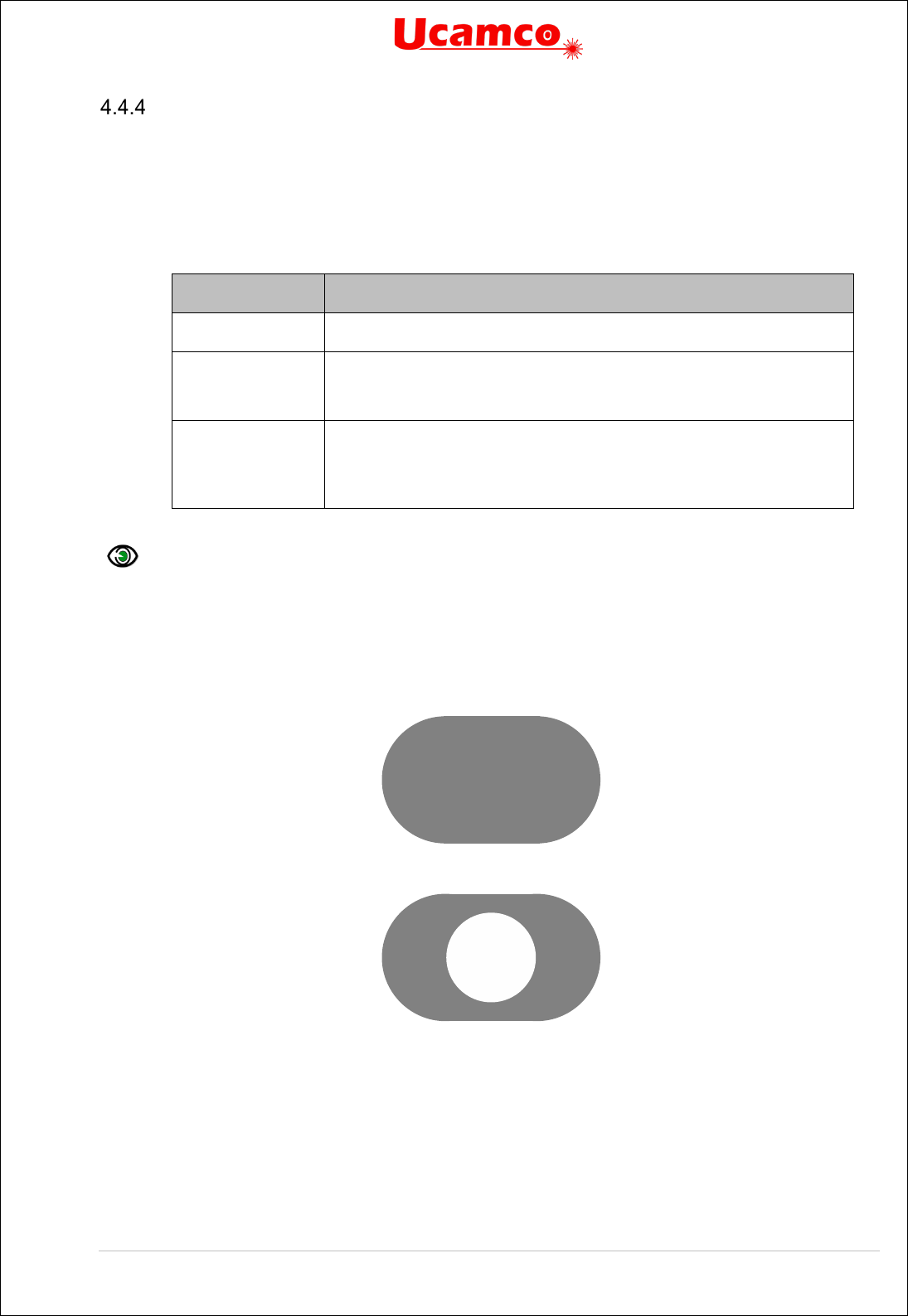
Copyright Ucamco NV 52
Having a question or remark about the spec? Please contact us at gerber@ucamco.com
Obround
Obround (oval) is a shape consisting of two semicircles connected by parallel lines tangent to
their endpoints. It can be viewed as a rectangle where the smallest side is rounded to a half-
circle. The syntax of the obround template call is:
template_call = 'O' ',' x_size 'X' y_size 'X' hole_diameter
Syntax
Comments
O
Indicates the obround aperture template.
x_size
y_size
X and Y sizes of enclosing box. Decimals >0.
If x_size = y_size the effective shape is a circle.
hole_diameter
Diameter of a round hole.
A decimal
>
0.
If omitted the aperture is
solid.
See also section 4.4.6.
Example:
%ADD22O,0.046X0.026*%
%ADD22O,0.046X0.026X0.019*%
These commands define the following apertures:
7. Obrounds

Copyright Ucamco NV 53
Having a question or remark about the spec? Please contact us at gerber@ucamco.com
Polygon
Creates a regular polygon aperture. The syntax of the polygon template is:
template_call = 'P' ',' outer_diameter 'X' vertices 'X' rotation 'X' hole_idameter
Syntax
Comments
P
Indicates the polygon aperture template.
outer_diameter Diameter of the circumscribed circle, i.e. the circle through the
polygon vertices. A decimal > 0.
vertices
Number of vertices n, 3 ≤ n ≤ 12. An integer.
rotation The rotation angle, in degrees counterclockwise. A decimal.
With rotation angle zero there is a vertex on the positive X-axis
through the aperture center.
hole_diameter
Diameter of a round hole.
A decimal
>
0.
If omitted the aperture
is solid.
See also section 4.4.6.
Examples:
%ADD17P,.040X6*%
%ADD17P,.040X6X0.0X0.019*%
These commands define the following apertures:
8. Polygons
Outer diameter
Out er diameter

Copyright Ucamco NV 54
Having a question or remark about the spec? Please contact us at gerber@ucamco.com
Transparency of Holes
Standard apertures may have a round hole in them. When an aperture is flashed only the solid
part affects the image, the hole does not. Objects under a hole remain visible through the hole.
For image generation the area of the hole behaves exactly as the area outside the aperture. The
hole is not part of the aperture.
Warning: Make no mistake: holes do not clear the objects under them.
For all standard apertures the round hole is defined by specifying its diameter as the last
parameter: <Hole diameter>. If <Hole diameter> is omitted the aperture is solid. If present the
diameter must be ≥ 0. The hole must strictly fit within the standard aperture. It is centered on the
aperture.
Example:
%FSLAX26Y26*%
%MOMM*%
%ADD10C,10X5*%
%ADD11C,1*%
G01*
%LPD*%
D11*
X-25000000Y-1000000D02*
X25000000Y1000000D01*
D10*
X0Y0D03*
M02*
9. Standard (circle) aperture with a hole above a draw
Note that the draw is visible through the hole.

Copyright Ucamco NV 55
Having a question or remark about the spec? Please contact us at gerber@ucamco.com
4.5 Aperture Macro (AM)
The AM command creates a macro aperture template and adds it to the aperture template
dictionary (see 2.2). A template is a parametrized shape. The AD command instantiates a
template into an aperture by suppling values to the template parameters.
Templates of any shape or parametrization can be created. Multiple simple shapes called
primitives can be combined in a single template. An aperture macro can contain variables
whose actual values are defined by:
Values provided by the AD command
Arithmetic expressions with other variables
The template is created by positioning primitives in a coordinate space. The origin of that
coordinate space will be the origin of all apertures created with the state.
A template must be defined before the first AD that refers to it. The AM command can be used
multiple times in a file.
Attributes are not attached to templates. They are attached to the aperture at the time of its
creation with the AD command.
An AM command contains the following words:
The AM declaration with the macro name
Primitives with their comma-separated parameters
Macro variables, defined by an arithmetic expression
The syntax for the AM command is:
AM = '%' ('AM' macro_name macro_body) '%';
macro_name = name '*';
macro_body = {in_macro_block}+;
in_macro_block =
|primitive
|variable_definition
;
variable_definition = (macro_variable '=' expression) '*';
macro_variable = '$' positive_integer;
primitive = primitive_code {',' par}*
par = ',' (expression);
Syntax
Comments
AM
AM for Aperture Macro
<Macro name> Name of the aperture macro. The name must be unique, it
cannot be reused for another macro. See 3.4.5
for the syntax
rules.
<Macro body> The macro body contains the primitives generating the image
and the calculation of their parameters.
<Variable definition> $n=<Arithmetic expression>. An arithmetic expression may
use arithmetic operators (described later), constants and
variables $m defined previously.
Copyright Ucamco NV 56
Having a question or remark about the spec? Please contact us at gerber@ucamco.com
Syntax
Comments
<Primitive> A primitive is a basic shape to create the macro. It includes
primitive code identifying the primitive and primitive-specific
parameters (e.g. center of a circle). See 4.5.1
. The primitives
are positioned in a coordinates system whose origin is the
origin of the resulting apertures.
<Primitive code>
A code specifying the primitive (e.g. polygon).
<Parameter> Parameter can be a decimal number (e.g. 0.050), a variable
(e.g. $1) or an arithmetic expression based on numbers and
variables. The actual value is calculated as explained in
4.5.4.3.
Coordinates and sizes are expressed in the unit set by the MO command.
A parameter can be either:
A decimal number
A macro variable
An arithmetic expression
A macro variable name must be a ‘$’ character followed by an integer >0, for example $12.
(This is a subset of names allowed in 3.4.3.)
Note: New lines can be added between words of a single command to enhance
readability. They do not affect the macro definition.
Example:
The following AM command defines an aperture macro named ‘Triangle_30’.
%AMTriangle_30*
4,1,3,
1,-1,
1,1,
2,1,
1,-1,
30*
%

Copyright Ucamco NV 57
Having a question or remark about the spec? Please contact us at gerber@ucamco.com
Primitives
4.5.1.1 Overview
Macro Primitives
Code
Name
Parameters
Ref.
0
Comment
A comment string
4.5.1.2
1
Circle
Exposure, Diameter, Center X, Center Y, Rotation
4.5.1.3
20
Vector Line
Exposure, Width, Start X, Start Y, End X, End Y, Rotation
4.5.1.4
21
Center Line
Exposure, Width, Hight, Center X, Center Y, Rotation
4.5.1.5
4
Outline
Exposure, # vertices, Start X, Start Y, Subsequent points..., Rotation
4.5.1.6
5
Polygon
Exposure, # vertices, Center X, Center Y, Diameter, Rotation
4.5.1.7
7 Thermal Center X, Center Y, Outer diameter, Inner diameter, Gap, Rotation
4.5.1.8
Table with macro primitives
Except for the comment all the parameters can be a decimal, integer, macro variables or am
arithmetic expression.

Copyright Ucamco NV 58
Having a question or remark about the spec? Please contact us at gerber@ucamco.com
4.5.1.2 Comment, Code 0
The comment primitive has no effect on the image but adds human-readable comments in an
AM command. The comment primitive starts with the ‘0’ code followed by a space and then a
single-line text string. The text string follows the syntax for strings in section 3.4.3.
Example:
%AMBox*
0 Rectangle with rounded corners, with rotation*
0 The origin of the aperture is its center*
0 $1 X-size*
0 $2 Y-size*
0 $3 Rounding radius*
0 $4 Rotation angle, in degrees counterclockwise*
0 Add two overlapping rectangle primitives as box body*
21,1,$1,$2-$3-$3,0,0,$4*
21,1,$2-$3-$3,$2,0,0,$4*
0 Add four circle primitives for the rounded corners*
$5=$1/2*
$6=$2/2*
$7=2X$3*
1,1,$7,$5-$3,$6-$3,$4*
1,1,$7,-$5+$3,$6-$3,$4*
1,1,$7,-$5+$3,-$6+$3,$4*
1,1,$7,$5-$3,-$6+$3,$4*%
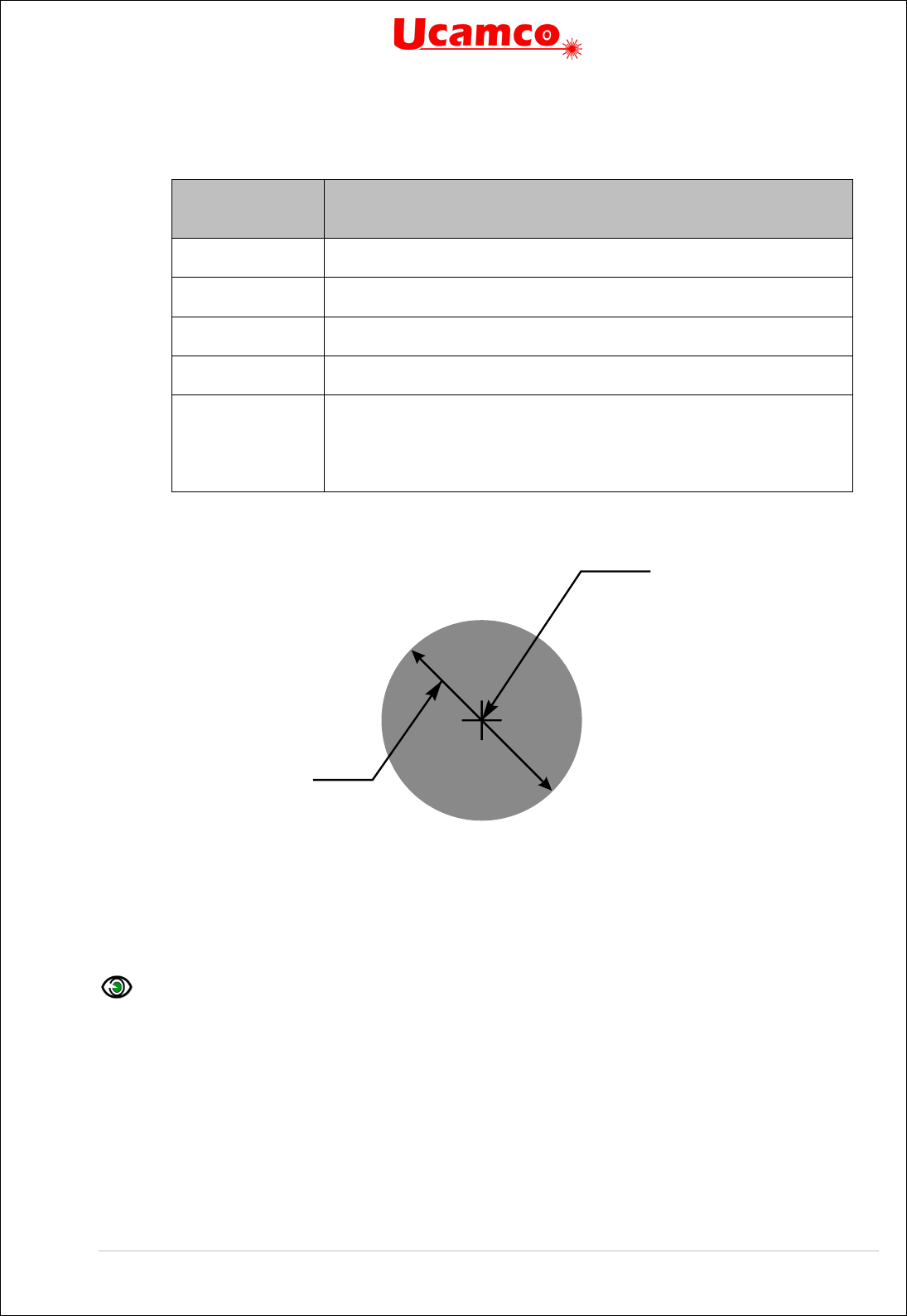
Copyright Ucamco NV 59
Having a question or remark about the spec? Please contact us at gerber@ucamco.com
4.5.1.3 Circle, Code 1
A circle primitive is defined by its center point and diameter.
Parameter
number
Description
1
Exposure off/on (0/1)
2
Diameter ≥ 0
3
Center X coordinate.
4
Center Y coordinate.
5 Rotation angle of the center, in degrees counterclockwise. The primitive
is rotated around the origin of the macro definition, i.e. the (0, 0) point of
macro coordinates.
The rotation parameter is optional. The default is no rotation.
10. Circle primitive
Below there is the example of the AM command that uses the circle primitive.
Example:
%AMCircle*
1,1,1.5,0,0,0*%
3, 4
2

Copyright Ucamco NV 60
Having a question or remark about the spec? Please contact us at gerber@ucamco.com
4.5.1.4 Vector Line, Code 20.
A vector line is a rectangle defined by its line width, start and end points. The line ends are
rectangular.
Parameter
number
Description
1
Exposure off/on. (0/1)
2
Width of the line
≥ 0.
3
Start point X coordinate.
4
Start point Y coordinate.
5
End point X coordinate.
6
End point Y coordinate.
7 Rotation angle, in degrees counterclockwise. The primitive is rotated
around the origin of the macro definition, i.e. the (0, 0) point of macro
coordinates
11. Vector line primitive
Below there is the example of the AM command that uses the vector line primitive.
Example:
%AMLine*
20,1,0.9,0,0.45,12,0.45,0*
%
3, 4
2
5, 6

Copyright Ucamco NV 61
Having a question or remark about the spec? Please contact us at gerber@ucamco.com
4.5.1.5 Center Line, Code 21
A center line primitive is a rectangle defined by its width, height, and center point.
Parameter
number
Description
1
Exposure off/on. (0/1)
2
Width
≥ 0.
3
Height
≥ 0.
4
Center point X coordinate.
5
Center point Y coordinate.
6 Rotation angle, in degrees counterclockwise. The primitive is rotated
around the origin of the macro definition, i.e. (0, 0) point of macro
coordinates.
Warning: The rotation is not around the center point. (Unless the
center point happens to be the macro origin.)
12. Center line primitive
Below there is the example of the AM command that uses the center line primitive.
Example:
%AMRECTANGLE*
21,1,6.8,1.2,3.4,0.6,30*%
2
4, 5
3

Copyright Ucamco NV 62
Having a question or remark about the spec? Please contact us at gerber@ucamco.com
4.5.1.6 Outline, Code 4
An outline primitive is an area defined by its outline or contour. The outline is a polygon,
consisting of linear segments only, defined by its start vertex and n subsequent vertices. The
outline must be closed, i.e. the last vertex must be equal to the start vertex. The outline must
comply with all the requirements of a contour according to 4.10.3.
Parameter
number
Description
1
Exposure off/on (0/1)
2 The number of vertices of the outline = the number of coordinate
pairs minus one. An integer ≥3.
3, 4
Start point X and Y coordinates.
5, 6
First subsequent X and Y coordinates.
... Further subsequent X and Y coordinates.
The X and Y coordinates are not modal: both X and Y must be
specified for all points.
3+2n, 4+2n Last subsequent X and Y coordinates. As the outline must be closed
the last coordinates must be equal to the start coordinates.
5+2n Rotation angle, in degrees counterclockwise, a decimal. The primitive is
rotated around the origin of the macro definition, i.e. the (0, 0) point of
macro coordinates.
13. Outline primitive
The maximum number of vertices is 5000. The purpose of this primitive is to create apertures to
flash pads with special shapes. The purpose is not to create copper pours. Use the region
statement for copper pours; see 4.10.
3, 4
5, 6
7, 8

Copyright Ucamco NV 63
Having a question or remark about the spec? Please contact us at gerber@ucamco.com
Example:
The following AM command defines an aperture macro named ‘Triangle_30’. The macro is a
triangle rotated 30 degrees around the origin of the macro definition:
%AMTriangle_30*
4,1,3,
1,-1,
1,1,
2,1,
1,-1,
30*
%
Syntax
Comments
AM Triangle _30
Aperture macro name is ‘Triangle _30’
4,1,3 4 – Outline
1 – Exposure on
3 – The outline has three subsequent points
1,-1 1 – X coordinate of the start point
-1 – Y coordinate of the start point
1,1,
2,1,
1,-1,
Coordinates (X, Y) of the subsequent points: (1,1), (2,1), (1,-1).
Note that the last point is the same as the start point
30
Rotation angle is 30 degrees counterclockwise
14. Rotated triangle
(0, 0)
Rotation center

Copyright Ucamco NV 64
Having a question or remark about the spec? Please contact us at gerber@ucamco.com
4.5.1.7 Polygon, Code 5
A polygon primitive is a regular polygon defined by the number of vertices n, the center point
and the diameter of the circumscribed circle.
Parameter
number
Description
1
Exposure off/on (0/1)
2 Number of vertices n, 3 ≤ n ≤ 12. An integer. The first vertex is on the
positive X-axis through the center point when the rotation angle is
zero.
3
Center point X coordinate. A
4
Center point Y coordinate.
5
Diameter of the circumscribed circle
≥ 0.
6 Rotation angle, in degrees counterclockwise.
With rotation angle zero
there is a vertex on the positive X-axis through the aperture center.
The primitive is rotated around the origin of the macro definition, i.e. the
(0, 0) point of macro coordinates.
15. Polygon primitive
Example:
%AMPolygon*
5,1,8,0,0,8,0*%
3, 4
5
First
vertex

Copyright Ucamco NV 65
Having a question or remark about the spec? Please contact us at gerber@ucamco.com
4.5.1.8 Thermal, Code 7
The thermal primitive is a ring (annulus) interrupted by four gaps. Exposure is always on.
Parameter
number
Description
1
Center point X coordinate.
2
Center point Y coordinate.
3
Outer diameter > inner diameter
4
Inner diameter ≥ 0
5
Gap thickness < (outer diameter)/√2. Note that if the (gap
thickness)*√2 ≥ (inner diameter) the inner circle disappears. This is
not invalid.
The gaps are on the X and Y axes through the center without
rotation. They rotate with the primitive.
6
Rotation angle, in degrees counterclockwise. A decimal.
The primitive is
rotated around the origin of the macro definition, i.e. (0, 0) point of
macro coordinates.
16. Thermal primitive
4
3
5

Copyright Ucamco NV 66
Having a question or remark about the spec? Please contact us at gerber@ucamco.com
Exposure Parameter
The exposure parameter that can take two values:
0 means exposure is ‘off’
1 means exposure is ‘on’
Primitives with exposure ‘on’ create the solid part of the macro aperture. Primitives with
exposure ‘off’ erase the solid part created earlier in the same macro. Exposure off is used to
create a hole in the aperture – see also 4.4.6.
The erasing action of exposure off only acts on other primitives within the same macro
definition. When a macro is flashed the hole does not clear objects in the final image – the hole
is transparent. Another way of expressing it is that the macro definition is flattened before it is
used, and the result is a positive image.
Warning: When the macro aperture is flashed, the erased area does not clear the
underlying graphical objects. Objects under removed parts remain visible.
Example:
%FSLAX26Y26*%
%MOMM*%
%AMSquareWithHole*
21,1,10,10,0,0,0*
1,0,5,0,0*%
%ADD10SquareWithHole*%
%ADD11C,1*%
G01*
%LPD*%
D11*
X-25000000Y-2000000D02*
X25000000Y1000000D01*
D10*
X0Y0D03*
M02*
17. Macro aperture with a hole above a draw

Copyright Ucamco NV 67
Having a question or remark about the spec? Please contact us at gerber@ucamco.com
Note that the draw is still visible through the hole.
Rotation Parameter
All primitives can be rotated around the origin of the macro definition, i.e. its point (0, 0). (Make
no mistake: rotation is not around the geometric center of the primitive, unless of course it
coincides with the origin.)
A rotation angle is expressed by a decimal number, in degrees counterclockwise. A positive
angle means counterclockwise rotation, a negative angle clockwise. The rotation angle is
defined by the rotation parameter, the last in the list of the primitive parameters.
To rotate a macro composed of several primitives it is sufficient to rotate all primitives by the
same angle. See illustration below.
18. Rotation of an aperture macro composed of several primitives
Warning: Rotation is around the origin of the macro definition, not around the geometric
center of the primitive – unless the two coincide of course. The reason is obvious: if rotation
were about the center of each primitive a composite aperture like the one above would fall apart
under rotation.
(0, 0)

Copyright Ucamco NV 68
Having a question or remark about the spec? Please contact us at gerber@ucamco.com
Macro Variables and Expressions
4.5.4.1 Variable Values from the AD Command
An AM command can use variables whose actual values are provided by the AD command
calling the macro. Such variables are identified by ‘$n’ where n indicates the index in the list of
the variable values provided by the AD command. Thus $1 means the first value in the list, $2
the second, and so on.
Example:
%AMDONUTVAR*1,1,$1,$2,$3*1,0,$4,$2,$3*%
$1, $2, $3 and $4 are macro variables. With the following calling AD
%ADD34DONUTVAR,0.100X0X0X0.080*%
the variables take the following values:
$1 = 0.100
$2 = 0
$3 = 0
$4 = 0.080
4.5.4.2 Arithmetic Expressions
A parameter value can also be defined by an arithmetic expression consisting of integer and
decimal constants, other variables, arithmetic operators and the brackets ‘(‘ and ‘)’. The
standard arithmetic precedence rules apply. The following arithmetic operators are available:
Operator
Function
+
Unary plus (expressions without the unary
sign are positive)
-
Unary minus
+
Add
-
Subtract
x (lower case)
Multiply
/
Divide. The result is a decimal; it is not
rounded or truncated to an integer.
Arithmetic operators
Example:
%AMRect*
21,1,$1,$2-2*$3,-$4,-$5+$2,0*%
The corresponding AD command could be:
%ADD146Rect,0.0807087X0.1023622X0.0118110X0.5000000X0.3000000*%
4.5.4.3 Definition of a New Variable
New variables can be defined by an assign statement as follows: $4=$1x1.25-$3. The
right-hand side is any arithmetic expression as in the previous section.

Copyright Ucamco NV 69
Having a question or remark about the spec? Please contact us at gerber@ucamco.com
Example:
%AMDONUTCAL*
1,1,$1,$2,$3*
$4=$1x1.25*
1,0,$4,$2,$3*%
The variable values are determined as follows:
$1, $2, ..., $n take the values of the n parameters of the calling AD command.
New variables get their value by evaluating their defining expression.
Undefined variables are 0.
Macro variables cannot be redefined.
Example:
%AMDONUTCAL*
1,1,$1,$2,$3*
$5=$1x0.75*
1,0,$5,$2,$3*%
%ADD35DONUTCAL,0.020X0X0X0.03*%
The AD command contains 4 parameters. The first four macro variables take the values: $1 =
0.02, $2 = 0, $3 = 0, $4 = 0.03. $5 is defined later and becomes $5 = 0.02 x
0.75 = 0.015.
Below are some more examples to illustrate the syntax to define macro variables. ues.
Examples:
%AMTEST1*
1,1,$1,$2,$3*
$4=$1x0.75*
$5=($2+100)x1.75*
1,0,$4,$5,$3*%
%AMTEST2*
$4=$1x0.75*
$5=100+$3*
1,1,$1,$2,$3*
1,0,$4,$2,$5*
$6=$4x0.5*
1,0,$6,$2,$5*%
Examples
4.5.5.1 Fixed Parameter Values
The following AM command defines an aperture macro named ‘DONUTFIX’ consisting of two
concentric circles with fixed diameter sizes:
%AMDONUTFIX*
1,1,0.100,0,0*
1,0,0.080,0,0*%

Copyright Ucamco NV 70
Having a question or remark about the spec? Please contact us at gerber@ucamco.com
Syntax
Comments
AMDONUTFIX
Aperture macro name is ‘DONUTFIX’
1,1,0.100,0,0 1 – Circle
1 – Exposure on
0.100 – Diameter
0 – X coordinate of the center
0 – Y coordinate of the center
1,0,0.080,0,0 1 – Circle
0 – Exposure off
0.080 – Diameter
0 – X coordinate of the center
0 – Y coordinate of the center
An example of an AD command using this aperture macro:
%ADD33DONUTFIX*%
4.5.5.2 Variable Parameter Values
The following AM command defines an aperture macro named ‘DONUTVAR’ consisting of two
concentric circles with variable diameter sizes:
%AMDONUTVAR*
1,1,$1,$2,$3*
1,0,$4,$2,$3*%
Syntax
Comments
AMDONUTVAR
Aperture macro name is ‘DONUTVAR’
1,1,$1,$2,$3 1 – Circle
1 – Exposure on
$1 – Diameter is provided by AD command
$2 – X coordinate of the center is provided by AD command
$3 – Y coordinate of the center is provided by AD command
1,0,$4,$2,$3 1 – Circle
0 – Exposure off
$4 – Diameter is provided by AD command
$2 – X coordinate of the center is provided by AD command (same
as in first circle)
$3 – Y coordinate of the center is provided by AD command (same
as in first circle)
The AD command using this aperture macro can look like the following:
%ADD34DONUTVAR,0.100X0X0X0.080*%

Copyright Ucamco NV 71
Having a question or remark about the spec? Please contact us at gerber@ucamco.com
In this case the variable parameters get the following values: $1 = 0.100, $2 = 0, $3 = 0, $4 =
0.080.
4.5.5.3 Definition of a New Variable
The following AM command defines an aperture macro named ‘DONUTCAL’ consisting of two
concentric circles with the diameter of the second circle defined as a function of the diameter of
the first:
%AMDONUTCAL*
1,1,$1,$2,$3*
$4=$1x0.75*
1,0,$4,$2,$3*%
Syntax
Comments
AMDONUTCAL
Aperture macro name is ‘DONUTCAL’
1,1,$1,$2,$3 1 – Circle
1 – Exposure on
$1 – Diameter is provided by AD command
$2 – X coordinate of the center is provided by AD command
$3 – Y coordinate of the center is provided by AD command
$4=$1x0.75 Defines variable $4 to be used as the diameter of the inner circle;
the diameter of this circle is 0.75 times the diameter of the outer
circle
1,0,$4,$2,$3 1 – Circle
0 – Exposure off
$4 – Diameter is calculated with the previous definition of this
variable
$2 – X coordinate of the center is provided by AD command (same
as in first circle)
$3 – Y coordinate of the center is provided by AD command (same
as in first circle)
The AD command using this aperture macro can look like the following:
%ADD35DONUTCAL,0.020X0X0*%
This defines a donut with outer circle diameter equal to 0.02 and inner circle diameter equal to
0.015.

Copyright Ucamco NV 72
Having a question or remark about the spec? Please contact us at gerber@ucamco.com
4.5.5.4 A useful macro
The following example creates a rectangle with rounded corners, useful as SMD pad.
It uses the following construction:
19. Construction of the Box macro
%AMBox*
0 Rectangle with rounded corners, with rotation*
0 The origin of the aperture is its center*
0 $1 X-size*
0 $2 Y-size*
0 $3 Rounding radius*
0 $4 Rotation angle, in degrees counterclockwise*
0 Add two overlapping rectangle primitives as box body*
21,1,$1,$2-$3-$3,0,0,$4*
21,1,$2-$3-$3,$2,0,0,$4*
0 Add four circle primitives for the rounded corners*
$5=$1/2*
$6=$2/2*
$7=2x$3*
1,1,$7,$5-$3,$6-$3,$4*
1,1,$7,-$5+$3,$6-$3,$4*
1,1,$7,-$5+$3,-$6+$3,$4*
1,1,$7,$5-$3,-$6+$3,$4*%

Copyright Ucamco NV 73
Having a question or remark about the spec? Please contact us at gerber@ucamco.com
4.6 Set Current Aperture (Dnn)
The command Dnn (nn
≥10)
sets the current aperture graphics state parameter. The syntax is:
Dnn = 'D unsigned_integer '*';
Syntax
Comments
D
Command code
<aperture number> The aperture number (integer ≥10). An aperture with
that number must be in the apertures dictionary.
D-commands 0 to 9 are reserved and cannot be used for apertures. The D01 and D03
commands use the current aperture to create track and flash graphical objects.
Example:
D10*

Copyright Ucamco NV 74
Having a question or remark about the spec? Please contact us at gerber@ucamco.com
4.7 Interpolation State Commands (G01,G02,G03,G75)
Linear Interpolation (G01)
G01 sets linear interpolation mode. In linear interpolation mode a D01 operation generates a
linear segment, from the current point to the (X, Y) coordinates in the command. The current
point is then set to the (X, Y) coordinates.
The segment is stroked with the current aperture to create a draw graphical object, except in a
region statement where the segment is added to the contour under construction.
The G01 command sets linear operation. The syntax is as follows:
G01 = ('G01') '*';
Syntax
Comments
G01 Sets interpolation mode graphics state parameter to ‘linear
interpolation’
D01 = (['X' x_coordinate] ['Y' y_coordinate] 'D01') '*';
Syntax
Comments
x_coordinate An integer specifying the X coordinate of the end point of the straight
segment. The default is the X coordinate of the current point.
y_coordinate
As above, but for the Y axis.
D01
Interpolate operation code
The coordinates are interpreted as specified by the FS and MO command.
Example:
G01*
X250000Y155000D01*
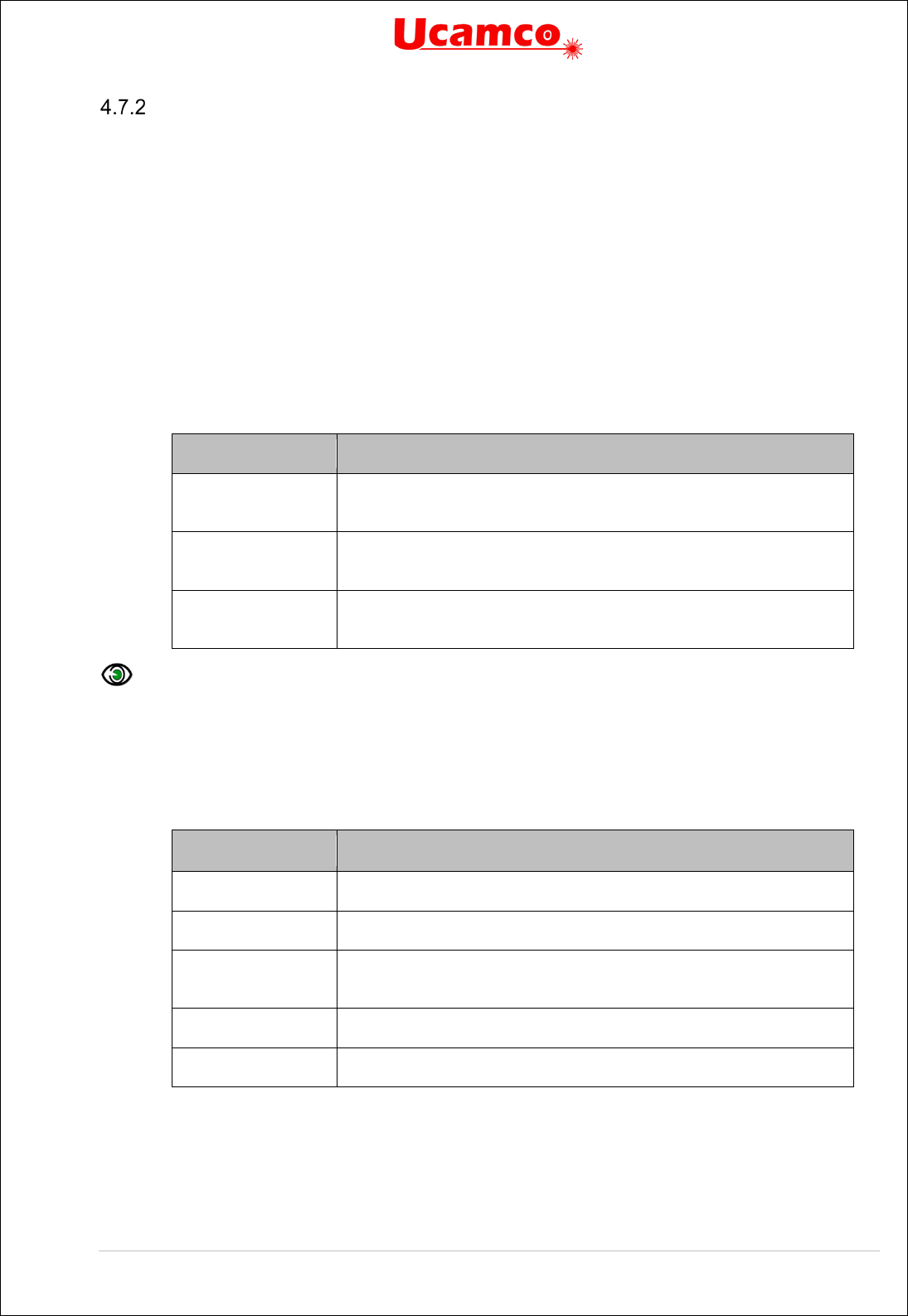
Copyright Ucamco NV 75
Having a question or remark about the spec? Please contact us at gerber@ucamco.com
Circular Interpolation (G02, G03, G75)
G02 sets clockwise circular interpolation mode, G03 counterclockwise. In circular interpolation
mode a D01 operation generates an arc segment, from the current point to the (X, Y)
coordinates in the command. The current point is then set to the (X, Y) coordinates.
The segment is stroked with the current aperture to create an arc graphical object, except in a
region statement where the segment is added to the contour under construction.
For compatibility with older versions of the Gerber format, a G75* must be issued before the first
D01 in circular mode.
The syntax of these commands is:
G02 = ('G02') '*';
G03 = ('G03') '*';
G75 = ('G75') '*';
Syntax
Comments
G02 Sets interpolation mode graphics state parameter to
‘clockwise circular interpolation’
G03 Sets interpolation mode graphics state parameter to
‘counterclockwise circular interpolation’
G75 This command must be issued before the first circular interpolation
operation, for compatibility with older Gerber versions
Examples:
G02*
G75*
The syntax of the D01 command in circular interpolation mode is:
D01 = (['X' x_coordinate] ['Y' y_coordinate] 'D01' 'I' x_offset 'J' y-offset ) '*';
Syntax
Comments
x_coordinate
x_coordinate
x_coordinate
As above, but for the Y axis.
i_offset Add the I offset to the X coordinate of the start point of the arc to
calculate the X of the center of the arcs. <Offset> is an integer.
j_offset
As above, but for the Y axis.
D01
Interpolate operation code
The coordinates and offsets are interpreted according as specified by the FS and MO
command.
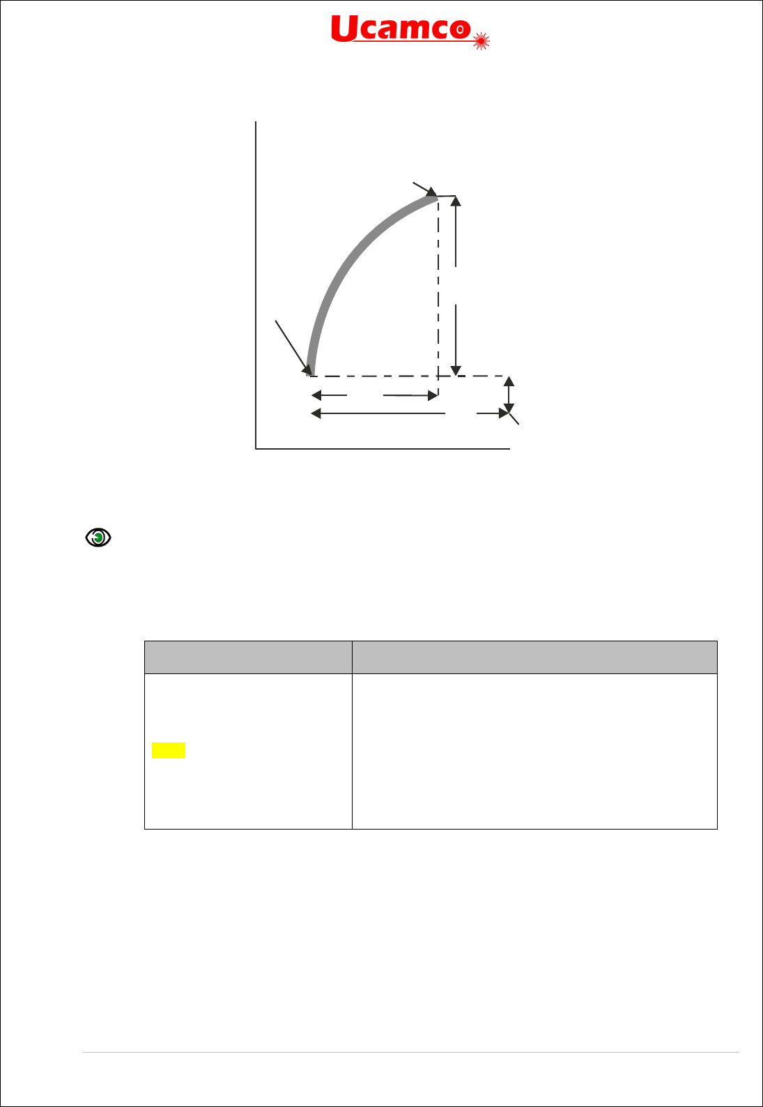
Copyright Ucamco NV 76
Having a question or remark about the spec? Please contact us at gerber@ucamco.com
20. Circular interpolation example
Example:
G75*
G03*
X75000Y50000I40000J0D01*
When start point and end point coincide the result is a full 360° arc. An example:
Syntax
Comments
D10*
G01*
X0Y600D02*
G75*
G02*
X0Y600I500J0D01*
Select aperture 10 as current aperture
Set linear interpolation mode
Set the current point to (0, 6)
Must be called before an arc is created.
Set clockwise circular interpolation mode
Create arc object to (0, 6) with center (5,6)
The resulting image is a full circle.
Note that arcs where the start point and end point of an arc very close together are unstable: a
small change in their relative position can turn a large arc in a small one and vice versa,
dramatically changing the image. A typical case is very small arcs: start and end point are close
together; if due to rounding the end point is slightly moved to coincide with the start point the
small arc becomes a full arc.
Rounding must be done carefully. Using high resolution is an obvious prerequisite. See 4.14.
The Gerber writer must also consider that the reader unavoidably has rounding errors. Perfectly
exact numerical calculation cannot be assumed. It is the responsibility of the writer to avoid
unstable arcs. Arcs shorter than say 2μm must be replaced with a draw - draws are intrinsically
Y axis
0,0
X axis
X
Y
J
End point
Start point
(current
point)
Arc center
I

Copyright Ucamco NV 77
Having a question or remark about the spec? Please contact us at gerber@ucamco.com
stable and the error is negligible. Near full arcs must be cut in two big arcs, which too are
intrinsically stable.
Warning: A Gerber file that attempts to create an arc without a preceding G75 is invalid.
4.7.2.1 Example
Syntax
Comments
X3000000Y-2000000D02*
G75*
G03*
X-3000000Y-2000000I-
3000000J4000000D01*
Set the current point to (3, -2) mm
Must be called before an arc is created
Set counterclockwise interpolation mode
Create arc object counterclockwise to (-3,-2). The
offsets from the start point to the center point are
3 for X and 4 for Y, i.e. the center point is (0, 2)
21. Arc example
4.7.2.2 Valid Arcs
Mathematically, the distance from the center to the start point must be exactly equal to the
distance to the end point. However, a Gerber file has a finite resolution. It is therefore generally
not possible to position the center point exactly so that both distances – radii - are indeed
exactly equal. Furthermore, the software generating the Gerber file unavoidably adds rounding
errors of its own. In real files the center is unavoidably not positioned exactly, and the two radii
are not equal. We will call the difference between the start and end radius the arc deviation.
End point (-3, -2)
Start point (3, -2)
(0, 0)
Arc center (0, 2)

Copyright Ucamco NV 78
Having a question or remark about the spec? Please contact us at gerber@ucamco.com
A mathematically exact circle has of course zero deviation. The interpretation of the arc
command is then obvious. However, which curve is represented by a “circular arc” with a non-
zero deviation? It cannot be a circular arc with the given center. Either it is not circular, it has
another center, or it does not go from start to end. The curve is defined as follow.
Any continuous and monotonic curve starting at the start point and ending at the end point,
approximating the ring with the given center point and with inner and outer radii equal to the
start radius and end radius is a valid rendering of the arc command. See figure below.
22. Arc with a non-zero deviation
The arc therefore has a fuzziness of the order of magnitude of the arc deviation. The writer of
the Gerber file accepts any interpretation within the fuzziness above as valid. If the writer
requires a more precise interpretation of the arc he needs to write more precise arcs, with lower
deviation.
It is however not allowed to place the center point close to the straight line through begin and
end point except when it is strictly in between these points. When the center is on or outside the
segment between start and end point the construct is nonsensical. See figure below.
23. Nonsensical center point
Note that self-intersecting contours are not allowed, see 4.10.3. If any of the valid arc
interpretations turns the contour in a self-intersecting one, the file is invalid, with unpredictable
results.
The root cause of most problems with arcs is the use a low resolution. One sometimes attempts
to force arcs of size of the order of e.g. 1/10 of a mil in a file with resolution of 1/10. This is
asking for problems. Use higher resolution. See 4.14.

Copyright Ucamco NV 79
Having a question or remark about the spec? Please contact us at gerber@ucamco.com
4.8 Operations (D01/D02/D03)
Overview
Commands consisting of coordinate data followed by a D01, D02 or D03 function code are
called operations.
Operation with D01 code is called interpolate operation. It creates a straight-line segment or
a circular segment by interpolating from the current point to the operation coordinates. The
segment is then stroked with the current aperture to generate a draw or arc graphical
object, except in a region statement where the segment is added to the contour being
constructed. The current point is moved to operations coordinate before processing the
next command.
Operation with D02 code is called move operation. It moves the current point to the
operation coordinates. No graphical object is generated.
Operation with D03 code is called flash operation. It creates a flash object by replicating
(flashing) the current aperture at the operation coordinates. When the aperture is flashed
its origin is positioned at the coordinates of the operation. The origin of a standard aperture
is its geometric center. The origin of a macro aperture is the origin used in the defining AM
command. The current point is moved to operations coordinate before processing the next
command.
The operations are controlled by the graphics state (see 2.5), as summarized in the table below.
G01 sets linear, G02 clockwise and G03 counterclockwise circular interpolation.
Operation
code
Inside a region statement (G36/G37) Outside a region statement
Linear mode
(G01)
Circular mode
(G02, G03)
Linear mode
(G01)
Circular mode
(G02, G03)
D01
Adds linear segment
to the contour under
construction
Moves current point
Adds circular
segment to the
contour under
construction
Moves current point
Creates a draw
Moves current point
Creates an arc
Moves current point
D02
Starts a new contour
Moves current point
Moves current point
D03 Not allowed
Creates a flash
Moves current point
Effect of operation codes depending on graphics state

Copyright Ucamco NV 80
Having a question or remark about the spec? Please contact us at gerber@ucamco.com
The parameters of the operations are coordinate data, see Error! Reference source not
found.. The FS and MO commands specify how to interpret the coordinate data.
Examples:
X200Y200D02* move to (+200, +200)
Y-300D03*
flash at (+200, -300)
I300J100D01*
interpolate to (+200, -300) with center offset (+300, +100)
Y200I50J50D01*
interpolate to (+200, +200) with center offset (+50, +50)
X200Y200I50J50D01*
interpolate to (+200, +200) with center offset (+50, +50)
X+100I-50D01*
interpolate to (+100, +200) with center offset (-50, 0)
D03* flash at (+100,+200)

Copyright Ucamco NV 81
Having a question or remark about the spec? Please contact us at gerber@ucamco.com
Interpolate (D01)
Performs an interpolation operation, creating a draw or an arc segment. The interpolation state
defines which type of segment is created, see 4.7. The syntax depends on the required
parameters, and, hence, on the interpolation state.
Interpolation
state
Syntax
Linear (G01)
D01 = (['X' x_coordinate] ['Y' y_coordinate] 'D01') '*';
Circular (G02|G03)
D01 = (['X' x_coordinate] ['Y' y_coordinate] 'D01' 'I' x_offset 'J'
y-offset ) '*';
Syntax
Comments
x_coordinate <Coordinate> is coordinate data – see section 0. It defines the X coordinate of the
new current point. The default is the X coordinate of the old current point.
x_coordinate
As above, but for the Y coordinate
i_offset <Offset> is the offset in X – see section 0. It defines the X coordinate the center of the
circle. It is of the coordinate type. There is no default offset.
j_offset
As above, but for the Y axis.
D01
Move operation code
After the interpolation operation the current point is set to X,Y.
Move (D02)
Moves the current point to the (X,Y) in the comment. The syntax is:
D02 = (['X' x_coordinate] ['Y' y_coordinate] 'D02') '*';
Syntax
Comments
x_coordinate <Coordinate> is coordinate data – see section 0. It defines the X
coordinate of the new current point. The default is the X coordinate of
the old current point.
x_coordinate
As above, but for the Y coordinate.
D02
Move operation code
The D02 command sets the new value for the current point. Inside a region statement it also
closes the current contour and starts a new one. (see 4.10).
Example:
X2152000Y1215000D02*
Flash (D03)
Performs a flash operation, creating a flash object at (X,Y). The syntax is:

Copyright Ucamco NV 82
Having a question or remark about the spec? Please contact us at gerber@ucamco.com
D02 = (['X' x_coordinate] ['Y' y_coordinate] 'D02') '*';
Syntax
Comments
x_coordinate <Coordinate> is an integer specifying the X coordinate of the
aperture origin. The default is the X coordinate of the old current point.
x_coordinate
As above, but for the Y coordinate.
D03
Flash operation code
Example:
X1215000Y2152000D03*
After the flash operation the current point is set to (X,Y).
Example
The example shows a stream of commands in a Gerber file. Some of the commands are
operation codes, others are G code commands (G01, G03, G36, G37, G74, and G75). The G
code commands set the graphics state parameters that are relevant for the operations:
interpolation mode (G01, G02, G03, G75) – see 4.7.
Example:
X275000Y115000D02*
G01*
X2512000Y115000D01*
G75*
G03*
X5005000Y3506000I3000J0D01*
G01*
X15752000D01*
Y12221000D01*

Copyright Ucamco NV 83
Having a question or remark about the spec? Please contact us at gerber@ucamco.com
4.9 Aperture Transformations ( L P, LM, LR, LS)
Overview
The commands LP, LM, LR and LS load the following object transformation graphics state
parameters:
Object transformation commands
Command
Long name
Parameter
LP
Load polarity
Polarity (Positive, Negative)
LM
Load mirroring
Mirror axis (N|X|Y|XY)
LR
Load rotation
Rotation angle
LS
Load scaling
Scaling factor
An object transformation parameter transforms the current aperture when it is used to create
object. The transformation is temporary, after the object is created the current aperture returns
to its original value. Consequently, the parameter is always applied on the original shape of the
current aperture.
The polarity option directly sets the polarity of the objects. The mirror/rotate/scale parameters
affect the shape of the objects by temporarily transforming the current aperture before the object
is created. Flashes are mirrored/rotated/scaled around the flash point according to the
transformation parameters. Draws and arcs (D01) are also affected; however, the only useful
application seems to rotate a square aperture to align it with a draw. As the current aperture
does not affect regions shape, the mirror/rotate/scale parameters do not affect the region shape
either.
Object transformation parameters become effective immediately after loading and remain in
effect until a new value is loaded. No other command alters the object transformation
parameters. The object transformation parameters affect nor the aperture dictionary nor the
current aperture.
Example on how the parameter changes affect the image
D123* Select D123
X5000Y7000D03* Flash D123
%LR90.0*% Set object rotation to 90 degrees
X6000Y8000D03* Flash D123 rotated 90 degrees
D124* Select D124
X6000Y8000D03* Flash D124 rotated 90 degrees
%LR0.0*% Set object rotation to 0 degrees
X7000Y9000D03* Flash D124, not rotated
D123* Select D123
X1000Y2000D03* Flash D123, this is the original, not rotated

Copyright Ucamco NV 84
Having a question or remark about the spec? Please contact us at gerber@ucamco.com
Example of the effect on interpolations (draws and arcs)
%MOMM*%
%FSLAX26Y26*%
%ADD10C,1*% Define aperture 10 as a 1mm circle
D10*
Select aperture 10
G01*
Set linear interpolation
X00000000Y00000000D02*
Move to origin
X01000000D01*
Draw a 1mm thick line
%LS1.5*%
Set scale factor to 1.5
Y02000000D01*
Draw a 1.5mm thick line
M02*
This results in the following image:

Copyright Ucamco NV 85
Having a question or remark about the spec? Please contact us at gerber@ucamco.com
Load Polarity (LP)
The LP command sets the polarity graphics state parameter, see 2.5. It defines the polarity
applied to objects when they are created. Polarity can be either dark or clear. Its effect is explained
in 2.7. There is an example in 4.10.4.6. The syntax for the LP command is:
LP = '%' ('LP' ('C'|'D')) '*%';
Syntax
Comments
LP
LP for Load Polarity
C|D
C – clear polarity
D – dark polarity
The LP command can be used multiple times in a file. The polarity remains as set until overruled
by another LP command.
Load Mirroring (LM)
The LM command sets the mirroring graphics state parameter, see 2.5. The mirroring option
defines the mirroring axis used when creating objects. The aperture is mirrored around its origin
(which may not be its geometric center) before being used. The syntax for the LM command is:
LM = '%' ('LM' ('N'|'XY'|'Y'|'X')) '*%';
Syntax
Comments
LM
LM for Load Mirroring
N|X|Y|XY
N – No mirroring
X – Mirroring along the X axis; mirror left to right; the signs of the x
coordinates are inverted
Y – Mirroring along the Y axis; mirror top to bottom; the signs of the
y coordinates are inverted
XY – Mirroring along both axes; mirror left to right and top to bottom;
the signs of both the x and y coordinates are inverted
Mirroring is performed before the rotation.
The LM command can be used multiple times in a file. The mirroring remains as set until overruled
by another LM command. Mirroring is set at the value in the command, it is not cumulated with
the previous value.
The LM command was introduced in revision 2016.12.
Load Rotation (LR)
The LR command sets the rotation graphics state parameter, see 2.5. It defines the rotation angle
used when creating objects. The aperture is rotated around its origin (which may or may not be
its geometric center). The syntax for the LR command is:
LR = '%' ('LR' decimal) '*%';
Syntax
Comments
LR
LR for Load Rotation
<Rotation>
The rotation angle, in degrees, counterclockwise. A decimal.
Mirroring is performed before the rotation.

Copyright Ucamco NV 86
Having a question or remark about the spec? Please contact us at gerber@ucamco.com
The LR command can be used multiple times in a file. The object rotation remains as set until
overruled by a subsequent LR command. Rotation is set at the value in the command, it is not
cumulated with the previous value.
The LR command was introduced in revision 2016.12.
Load Scaling (LS)
The LS command sets the scaling graphics state parameter, see 2.5. It defines the scale factor
used when creating objects. The aperture is scaled centered on its origin (which may or may not
be its geometric center). The syntax for the LS command is:
LS = '%' ('LS' decimal) '*%';
Syntax
Comments
LS
LS for Load Scaling
<Scale>
A decimal > 0.
The LS command can be used multiple times in a file. The object scaling remains as set until
overruled by a subsequent LS command. Scaling is set at the value in the command, it is not
cumulated with the previous scale factor.
The LS command was introduced in revision 2016.12.
Examples
Syntax
Comments
%LPD*%
Sets the object polarity to dark
%LPC*%
Sets the object polarity to clear
%LMX*%
Sets object mirroring to mirroring along the X axis
%LMN*%
Sets object mirroring to no mirroring
%LR45.0*%
Sets object rotation to 45 degrees counterclockwise
%LR-90*%
Sets object rotation to 90 degrees clockwise
%LS0.8*%
Sets object scaling to 80%

Copyright Ucamco NV 87
Having a question or remark about the spec? Please contact us at gerber@ucamco.com
Example of a block flashed in different mirroring, orientation, scaling
G04 Ucamco copyright*
%TF.GenerationSoftware,Ucamco,UcamX,2016.04-160425*%
%TF.CreationDate,2016-04-25T00:00:00+01:00*%
%FSLAX26Y26*%
%MOMM*%
%ADD10C,1*%
%LPD*%
G04 Define block aperture D12*
%ABD12*%
%ADD11C,0.5*%
D10*
G01*
X-2500000Y-1000000D03*
Y1000000D03*
%LPC*%
D11*
X-2500000Y-1000000D03*
%LPD*%
X-500000Y-1000000D02*
X2500000D01*
G75*
G03*
X500000Y1000000I-2000000J0D01*
G01*
%AB*%
G04 Flash block aperture D12 in four different orientation*
D12*
X0Y0D03*
%LMX*%
X10000000D03*
%LMY*%
%LR30.0*%
X0Y8000000D03*
%LMXY*%
%LR45.0*%
%LS0.8*%
X10000000D03*
%LPD*%
%LMN*%
%LR0.0*%
%LS1.0*%
M02*


Copyright Ucamco NV 89
Having a question or remark about the spec? Please contact us at gerber@ucamco.com
4.10 Region Statement (G36/G37)
Region Overview
A region is a graphical object defined by its contour(s) - see 4.10.3.
The G36 command begins a region statement and G37 ends it. A region statement creates
contour objects by defining its contour. In a region statement the D01 and D02 commands
create the contour segments. The first D01 encountered in a region statement starts the first
contour by creating the first segment. Subsequent D01’s add segments to it. When a D02
command is encountered the contour is considered finished. (Note that a D02 without effect on
the current point, e.g. a D02*, also finishes the current contour. ) A D02 is only allowed if the
preceding contour is closed. The next D01 command starts a new contour. Thus an unlimited
number of contours can be created between a single G36/G37 commands pair.
When a G37 command is encountered, the region statement is closed and region graphical
objects are added to the object stream by filling the newly created contours. All object and
aperture objects are attached to the region. A G37 is only allowed when all contours are
properly closed. A G37 finishes the last contour in the absence of a finishing D02. Each contour
is filled individually. The overall filled area is the union of the filled areas of each individual
contour. The number of region objects created by a single G36/G37 pair is intentionally not
specified to leave more freedom to implementations; - for example, two overlapping contours
may be merged in a single region object.
Holes in a region are defined with cut-ins (see 4.10.3 and 4.10.4.7).
D01 and D02 are the only D code commands allowed in a region statement; D03 and Dnn
(nn≥10) are not allowed. Extended commands are not allowed. The M02 (end-of-file) command
is not allowed. However, G code commands are allowed – they are needed to control the
interpolation state.
Contour segments are not in themselves graphical objects –they define the regions which are
graphical objects.
Aperture attributes can be attached to a region, see 5.3.1.

Copyright Ucamco NV 90
Having a question or remark about the spec? Please contact us at gerber@ucamco.com
Region Statement Syntax
The G36 and G37 commands begin and end a region statement respectively. The syntax is:
G36 = ('G36') '*';
G37 = ('G37') '*';
Syntax
Comments
G36
Begins a region statement.
G37 Ends a region statement.
This creates the set of region graphical object.
interpolation_state_command =
|G01
|G02
|G03
|G75
;
region_statement = G36 {contour}+ G37;
contour = D02 {D01|interpolation_state_command}*;
A valid contour must not only comply with this syntax, but the sequence of draws/arcs must
represent a connected closed contour that does not self-intersect. See 4.10.3.
Valid Contours
A contour is a sequence of connected linear or circular segments. A pair of segments is said to
connect only if they are defined consecutively, with the second segment starting where the first
one ends. Thus, the order in which the segments are defined is significant. Non-consecutive
segments that meet or intersect fortuitously are not considered to connect. A contour is closed:
the end point of the last segment must coincide with the start point of the first segment. A
contour thus defines a closed curve.
There are two classes of valid contours.
Simple contours. A contour is said to be simple if all its segments are disjoint, except for
consecutive segments having only their connection point in common. However, zero-length
segments have no effect: readers can remove them before processing the contour. (Avoid zero-
length segments as they are useless and can only cause confusion.) A simple contour does not
self-intersect or self-touch. The inside of the contour constitutes the region object. A simple
contour defines a simple region, without holes.
Simple cut-in contours. These contours allow to create a region with holes. A cut-in connects
the contour defining the hole to its enclosing contour, thus joining them into a single contour. If
one travels along the contour in the direction of the segments and the inside must always be to
the same side, just as for simple contours. See the illustration below; see 4.10.4.7
for a fully
worked out example.

Copyright Ucamco NV 91
Having a question or remark about the spec? Please contact us at gerber@ucamco.com
25. A contour with a cut-in
A cut-in is subject to strict requirements: it must consist of two fully coincident linear segments;
a pair of linear segments are said to be fully coincident if the segments coincide completely, with
the second segment starting where the first one ends; cut-ins must be either horizontal or
vertical; all cut-ins in a contour must have the same direction; cut-ins cannot intersect the
contour in any other location than their start and end points.
All contours except simple contours and simple cut-in contours are called self-intersecting and
are not allowed. Segments cannot cross, overlap or touch except
connected segments
cut-ins.
Any other form of self-touching or self-intersection is not allowed. For the avoidance of doubt,
not allowed are, amongst others: segments that partially overlap, fully coincident linear
segments that are diagonal, fully coincident circular segments, circular segments that are
tangent to another segment, vertices on a segment at another location than its endpoints, points
where more than two segments end, full arcs except when the contour consist solely of that full
arc or the full arc is at the end of a cut-in.
An invalid contour has no specified interpretation.
For the mathematically inclined: A contour is said to be weakly simple if there exists an
arbitrarily small perturbation of the vertices changing it in a simple contour. Simple contours with
cut-ins are weakly simple. The winding number for valid Gerber contours is for the outside 0 and
for the inside everywhere either +1 or -1, depending on the orientation. However, not all weakly
simple contours or contours with these winding numbers are valid.
Contours are also used to define outline primitives in macro apertures (see 4.5.1.6).
Processing Gerber files is inevitably subject to rounding errors. Contours must be constructed
robustly so that perturbations due to this rounding do not turn an otherwise valid contour in a
self-intersecting one. See 4.14.2.
In Gerber, the orientation of the contour is not significant.
Warning: Use maximum resolution. Low file coordinate resolution brings uncontrolled
rounding and often results in self-intersecting contours, see 4.1.
Warning: Sloppy construction of cut-ins can lead to self-intersecting contours – in fact this
is the most prevalent cause of missed clearances in planes. Construct cut-ins carefully or avoid
them altogether by making holes in regions with negative objects.
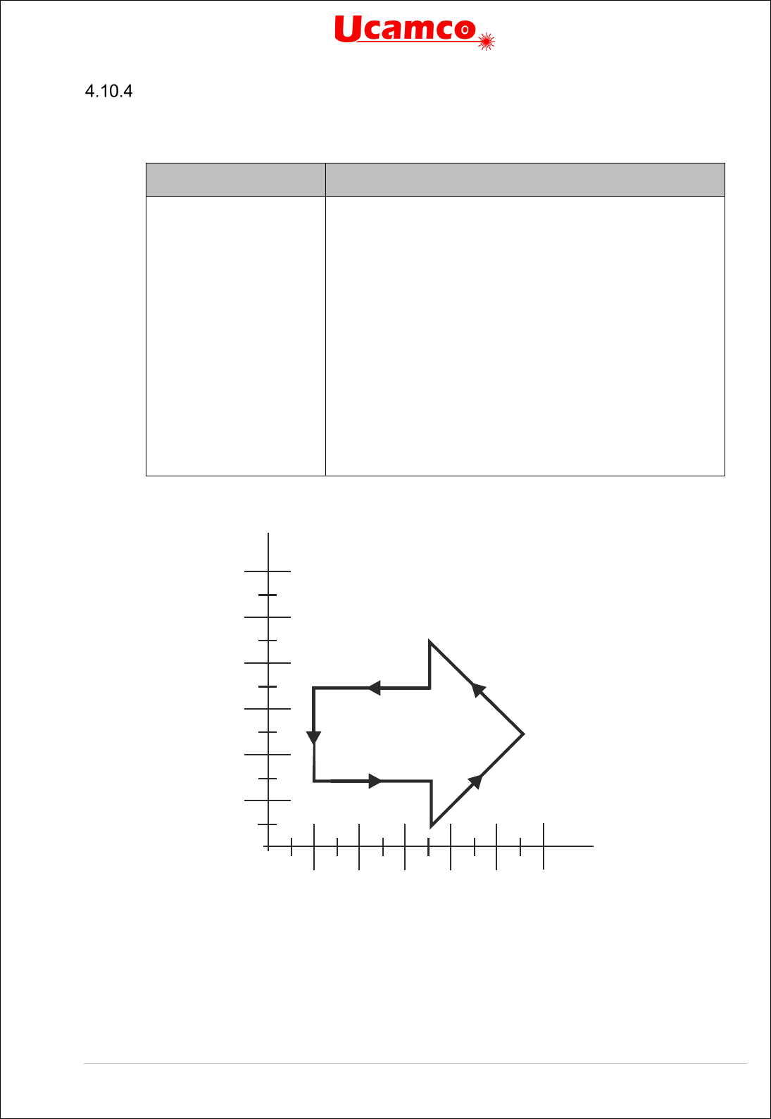
Copyright Ucamco NV 92
Having a question or remark about the spec? Please contact us at gerber@ucamco.com
Examples
4.10.4.1 A Simple Contour
Syntax
Comments
G36*
X200Y300000D02*
G01*
X700000D01*
Y100000D01*
X1100000Y500000D01*
X700000Y900000D01*
Y700000D01*
X200000D01*
Y300000D01*
G37*
Begins a region statement
Set the current point to (2, 3). Begin of a contour.
Set linear interpolation mode
Create linear segment to (7, 3)
Create linear segment to (7, 1)
Create linear segment to (11, 5)
Create linear segment to (7, 9)
Create linear segment to (7, 7)
Create linear segment to (2, 7)
Create linear segment to (2, 3), closing the contour.
Create the region by filling the contour
26. Simple contour example: the segments
2
4
6
8
10
12
2
4
6 8 10
12

Copyright Ucamco NV 93
Having a question or remark about the spec? Please contact us at gerber@ucamco.com
27. Simple contour example: resulting image
4.10.4.2 Use D02 to Start a Second Contour
D02 command can be used to start the new contour. All the created contours are converted to
regions when the command G37 is encountered. The example below creates two non-
overlapping contours which are then converted into two regions.
Example:
G04 Non-overlapping contours*
%FSLAX24Y24*%
%MOMM*%
%ADD10C,1.00000*%
G01*
%LPD*%
G36*
X0Y50000D02*
Y100000D01*
X100000D01*
Y0D01*
X0D01*
Y50000D01*
X-10000D02*
X-50000Y10000D01*
X-90000Y50000D01*
X-50000Y90000D01*
X-10000Y50000D01*
G37*
M02*
2
4
6 8 10
12
2
4
6
8
10
12

Copyright Ucamco NV 94
Having a question or remark about the spec? Please contact us at gerber@ucamco.com
This creates the following image:
28. Use of D02 to start a new non-overlapping contour
Two different contours were created. Each contour is filled individually. The filled area is the
union of the filled areas.
4.10.4.3 Overlapping Contours
The example below creates two overlapping contours which are then converted into one region.
Example:
G04 Overlapping contours*
%FSLAX24Y24*%
%MOMM*%
%ADD10C,1.00000*%
G01*
%LPD*%
G36*
X0Y50000D02*
Y100000D01*
X100000D01*
Y0D01*
X0D01*
Y50000D01*
X10000D02*
X50000Y10000D01*
X90000Y50000D01*
X50000Y90000D01*
X10000Y50000D01*
G37*
M02*

Copyright Ucamco NV 95
Having a question or remark about the spec? Please contact us at gerber@ucamco.com
This creates the following image:
29. Use of D02 to start a new overlapping contour
Two different contours were created. Each contour is filled individually. The filled area is the
union of the filled areas. As the second contour is completely embedded in the first, the effective
filled area is the one of the first contour. The created region object is the same as would be
defined by the first contour only.
4.10.4.4 Non-overlapping and Touching
The example below creates two non-overlapping touching contours which are then converted
into one region.
Example:
G04 Non-overlapping and touching*
%FSLAX24Y24*%
%MOMM*%
%ADD10C,1.00000*%
G01*
%LPD*%
G36*
X0Y50000D02*
Y100000D01*
X100000D01*
Y0D01*
X0D01*
Y50000D01*
D02*
X-50000Y10000D01*
X-90000Y50000D01*
X-50000Y90000D01*
X0Y50000D01*
G37*
M02*

Copyright Ucamco NV 96
Having a question or remark about the spec? Please contact us at gerber@ucamco.com
This creates the following image:
30. Use of D02 to start a new non-overlapping contour
As these are two different contours in the same region touching is allowed.
4.10.4.5 Overlapping and Touching
The example below creates two overlapping touching contours which are then converted into
one region.
Example:
G04 Overlapping and touching*
%FSLAX24Y24*%
%MOMM*%
%ADD10C,1.00000*%
G01*
%LPD*%
G36*
X0Y50000D02*
Y100000D01*
X100000D01*
Y0D01*
X0D01*
Y50000D01*
D02*
X50000Y10000D01*
X90000Y50000D01*
X50000Y90000D01*
X0Y50000D01*
G37*
M02*
This creates the following image:

Copyright Ucamco NV 97
Having a question or remark about the spec? Please contact us at gerber@ucamco.com
31. Use of D02 to start an new overlapping and touching contour
As these are two different contours in the same region touching is allowed.
4.10.4.6 Using Polarity to Create Holes
The recommended way to create holes in regions is by alternating dark and clear polarity, as
illustrated in the following example. Initially the polarity mode is dark. A big square region is
generated. The polarity mode is set to clear and a circular disk is added to the object stream;
the disk is cleared from the image and creates a round hole in the big square. Then the polarity
is set to dark again and a small square is added to the stream, darkening the image inside the
hole. The polarity is set to clear again and a small disk added, clearing parts of the big and the
small squares.
Example:
G04 This file illustrates how to use polarity to create holes*
%FSLAX25Y25*%
%MOMM*%
G01*
G04 First object: big square - dark polarity*
%LPD*%
G36*
X2500000Y2500000D02*
X17500000D01*
Y17500000D01*
X2500000D01*
Y2500000D01*
G37*
G04 Second object: big circle - clear polarity*
%LPC*%
G36*
G75*
X5000000Y10000000D02*
G03*
X5000000Y10000000I5000000J0D01*
G37*

Copyright Ucamco NV 98
Having a question or remark about the spec? Please contact us at gerber@ucamco.com
G04 Third object: small square - dark polarity*
%LPD*%
G01*
G36*
X7500000Y7500000D02*
X12500000D01*
Y12500000D01*
X7500000D01*
Y7500000D01*
G37*
G04 Fourth object: small circle - clear polarity*
%LPC*%
G36*
G75*
X11500000Y10000000D02*
G03*
X11500000Y10000000I2500000J0D01*
G37*
M02*
Below there are pictures which show the resulting image after adding each object.
32. Resulting image: first object only


Copyright Ucamco NV 100
Having a question or remark about the spec? Please contact us at gerber@ucamco.com
35. Resulting image: all four objects
4.10.4.7 A Simple Cut-in
The example below illustrates how a simple cut-in can be used to create a hole in a region. The
coinciding contour segments must follow the requirements defined in 4.10.3.
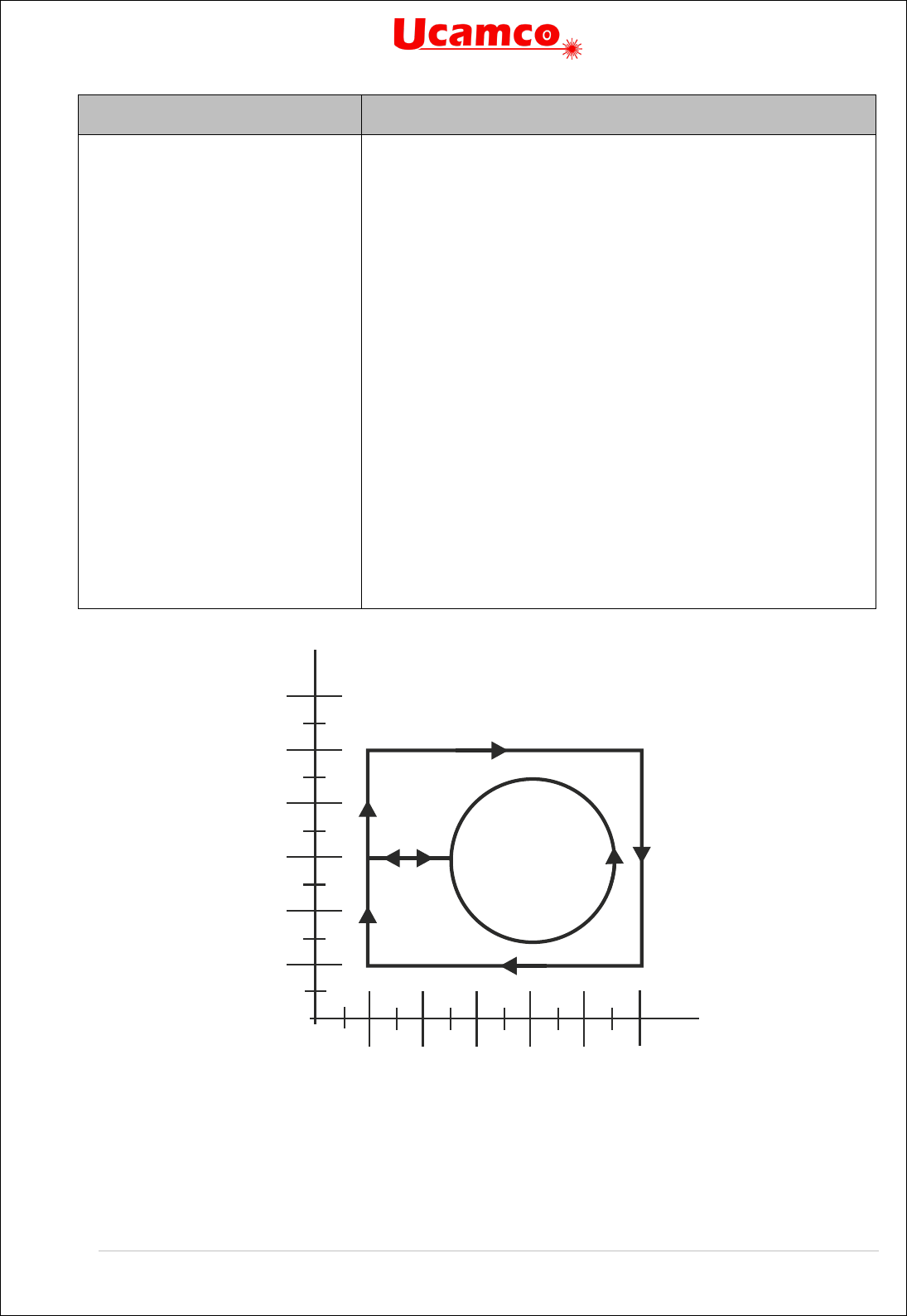
Copyright Ucamco NV 101
Having a question or remark about the spec? Please contact us at gerber@ucamco.com
Syntax
Comments
%FSLAX26Y26*%
G75*
G36*
X20000Y10000000D02*
G01*
X12000000D01*
Y20000000D01*
X2000000D01*
Y6000000D01*
X5000000D01*
G03*
X50000Y60000I30000J0D01*
G01*
X20000D01*
Y100000D01*
G37*
Format specification
Must be called before an arc is created
Begins a region statement
Set the current point to (2,10)
Set linear interpolation mode
Create linear contour segment to (12,10)
Create linear contour segment to (12, 2)
Create linear contour segment to (2, 2)
Create linear contour segment to (2, 6)
Create linear contour segment to (5, 6),1
st
fully coincident segment
Set counterclockwise circular interpolation mode
Create counterclockwise circle with radius 3
Set linear interpolation mode
Create linear contour segment to (2, 6), 2
nd
fully coincident segment
Create linear contour segment to (2, 10)
Create the region by filling the contour
36. Simple cut-in: the segments
2
4
6 8 10
12
2
4
6
8
10
12

Copyright Ucamco NV 102
Having a question or remark about the spec? Please contact us at gerber@ucamco.com
37. Simple cut-in: the image
Note the orientation of the inner circle. If the orientation would be different the contour would be
self-intersecting. This becomes immediately apparent if you try to perturb the contour to convert
it to a simple contour.
4.10.4.8 Fully Coincident Segments
The first example below illustrates how one contour may result in two regions. This happens
because there are two fully coincident linear segments which give the gap between filled areas.
Example:
G04 ex1: non overlapping*
%FSLAX24Y24*%
%MOMM*%
%ADD10C,1.00000*%
G01*
%LPD*%
G36*
X0Y50000D02*
Y100000D01*
X100000D01*
Y0D01*
X0D01*
Y50000D01*
G04 first fully coincident linear segment*
X-10000D01*
X-50000Y10000D01*
X-90000Y50000D01*
X-50000Y90000D01*
2
4
6 8 10
12
2
4
6
8
10
12
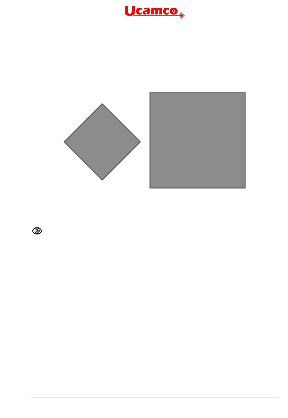
Copyright Ucamco NV 103
Having a question or remark about the spec? Please contact us at gerber@ucamco.com
X-10000Y50000D01*
G04 second fully coincident linear segment*
X0D01*
G37*
M02*
This creates the following image:
38. Fully coincident segments in contours: two regions
The second example illustrates how one contour allows creating region with hole.
Example:
G04 ex2: overlapping*
%FSLAX24Y24*%
%MOMM*%
%ADD10C,1.00000*%
G01*
%LPD*%
G36*
X0Y50000D02*
Y100000D01*
X100000D01*
Y0D01*
X0D01*
Y50000D01*
G04 first fully coincident linear segment*
X10000D01*
X50000Y10000D01*
X90000Y50000D01*
X50000Y90000D01*
X10000Y50000D01*
G04 second fully coincident linear segment*
X0D01*

Copyright Ucamco NV 104
Having a question or remark about the spec? Please contact us at gerber@ucamco.com
G37*
M02*
This creates the following image:
39. Fully coincident segments in contours: region with hole
4.10.4.9 Valid and Invalid Cut-ins
Contours with cut-ins are susceptible to rounding problems: when the vertices move due to the
rounding the contour may become self-intersecting. This may lead to unpredictable results. The
first example below is a cut-in with valid fully coincident segments, where linear segments which
are on top of one another have the same end vertices. When the vertices move due to rounding,
the segments will remain exactly on top of one another, and no self-intersections are created.
This is a valid and robust construction.
Example:
G36*
X1220000Y2570000D02*
G01*
Y2720000D01*
X1310000D01*
Y2570000D01*
X1250000D01*
Y2600000D01*
X1290000D01*
Y2640000D01*
X1250000D01*
Y2670000D01*
X1290000D01*
Y2700000D01*
X1250000D01*
Y2670000D01*
Y2640000D01*
Y2600000D01*
Y2570000D01*


Copyright Ucamco NV 106
Having a question or remark about the spec? Please contact us at gerber@ucamco.com
41. Valid cut-in: resulting image
The next example attempts to create the same image as the first example from above, but it is
invalid due to the use of invalid partially coinciding segments (see the description of a valid
contour in 4.10.3). The number of linear segments has been reduced by eliminating vertices
between collinear segments, creating invalid overlapping segments. This construction is invalid.
It is prohibited because it is not robust and hard to handle: when the vertices move slightly due
to rounding, the segments that were on top of one another may become intersecting, with
unpredictable results.
Example:
G36*
X1110000Y2570000D02*
G01*
Y2600000D01*
X1140000D01*
Y2640000D01*
X1110000D01*
Y2670000D01*
X1140000D01*
Y2700000D01*
X1110000D01*


Copyright Ucamco NV 108
Having a question or remark about the spec? Please contact us at gerber@ucamco.com
Power and Ground Planes
The simplest way to construct power and ground planes is first to create the copper pour with a
region in dark polarity (LPD), and then erase the clearances by switching to clear polarity (LPC)
and flash the anti-pads.
Example:
G04 We define the antipad used to create the clearances*
%TA.AperFunction,AntiPad*%
%ADD11C….*%
….
G04 We now define the copper pour as a region*
LPD*
G36*
X…Y…D02*
X…Y…D01*
…
G37*
G04 We now flash clearances*
%LPC*%
D11*
X…Y…D03*
This is simple and clear. In the CAD layout, the location of the anti-pads is known. With negative
anti-pads this information is transferred directly to CAM in a simple way.

Copyright Ucamco NV 109
Having a question or remark about the spec? Please contact us at gerber@ucamco.com
Clearances in power and ground planes can also be constructed with cut-ins, as below.
43. Power and ground planes with cut-ins.
The cut-ins are rather complex to create on output; on input in CAM the cut-ins must be
removed and the original clearances restored, again rather complex. Use this more complex
construction only if there is a good reason not to use the anti-pad method.

Copyright Ucamco NV 110
Having a question or remark about the spec? Please contact us at gerber@ucamco.com
Care must be taken to only create valid cut-ins. Sloppy cut-ins are the most frequent cause of
scrap due to faulty Gerber files, causing a self-intersecting contour and a missing clearance.
Below is an example of such sloppy cut-in; it is a real-life example that lead to expensive scrap.
Watch out for rounding errors. Make sure that coincident points indeed are coincident in the file.
With the highest resolution on outputs reduces rounding errors.
44. Power plane with invalid cut-in.
It is sometimes recommended to avoid the cut-ins altogether by splitting the plane in separate
pieces, where no piece has holes. Do not follow this terrible recommendation. The remedy is
worse than the disease. Splitting the single contour in separate contours without holes is as
complex as adding cut-ins. All clearance boundaries must be cut in pieces and split over
different contours; not much of an improvement over finding cut-in points. Rounding errors still
lurk, and can lead to pieces that are no longer connected; not much of an improvement over
invalid cut-ins. The situation is far worse on input. If the plane consists of a single contour it is
clear it is a single plane. When planes are split in pieces the coherence is lost. The file reader
must figure out from a bewildering set of contours that a single plane is intended. It must
recover clearances which boundaries are scattered over different contours. Cutting a plane in
pieces to avoid clearances is bad practice. It is asking for problems. See also 4.14.
Copyright Ucamco NV 111
Having a question or remark about the spec? Please contact us at gerber@ucamco.com
4.11 Block Aperture (AB)
Overview of block apertures
The AB command creates a block aperture. The command stream between the opening and
closing AB command defines a block aperture which is stored in the aperture dictionary. Thus
the AB commands add an aperture to the dictionary directly, without needing an AD command.
The LM, LR, LS and LP commands affect the flashes of block apertures in as any other
aperture: when a block aperture is flashed, it is first transformed according to the transformation
parameters in the graphics state and then added to the object stream.
The origin of the block aperture is the (0,0) point of the file.
A block aperture is not a single graphical object but a set of objects. While a standard or macro
aperture always adds a single graphical object to the stream, a block aperture can add any
number of objects, each with their own polarity. Standard and macro apertures always have a
single polarity while block apertures can contain both dark and clear objects.
If the polarity is dark (LPD) when the block is flashed then the block aperture is inserted as is. If
the polarity is clear (LPC) then the polarity of all objects in the block is toggled (clear becomes
dark, and dark becomes clear). This toggle propagates through all nesting levels. In the
following example the polarity of objects in the flash of block D12 will be toggled.
%ABD12*%
…
%AB*%
….
D12*
%LPC*%
X-2500000Y-1000000D03*
A D03 of a block aperture updates the current point but otherwise leaves the graphics state
unmodified, as with any other aperture.
The AB command was introduced in revision 2016.12
AB Statement Syntax
The syntax for the AB command is:
<AB command> = AB[<block aperture number>]*
Syntax
Comments
AB
AB for Aperture Block. Opens/closes an AB statement.
<block aperture
number>
The aperture number under which the block is stored in the
aperture dictionary.
Examples:
Syntax
Comments
%ABD12*%
Opens the definition of aperture D12
%AB*%
Closes the current AB statement.

Copyright Ucamco NV 112
Having a question or remark about the spec? Please contact us at gerber@ucamco.com
The section between the opening and closing AB commands can contain nested AB
commands. The resulting apertures are stored in the library and are available subsequently until
the end of the file, also outside the enclosing AB section. The syntax is:
AB_statement = AB_open {in_block_statement}* AB_close;
AB_open = '%' ('AB' aperture_ident) '*%';
AB_close = '%' ('AB') '*%';
in_block_statement =
|single_statement
|region_statement
|AB_statement
;
single_statement =
| operation
| interpolation_state_command
| Dnn
| G04
| attribute_command
| AD
| AM
| coordinate_command
| transformation_state_command
;
Consequently, an AB statement can contain embedded AB statements. The scope of names
defined by an AB statement is the whole file.
The current point is undefined after an AB statement.
Usage of Block Apertures
The main purpose of block apertures is to repeat a sub-image without the need to repeat all the
generating commands. Block apertures can be repeated at any location and individually mirrored,
rotated and scaled. Block apertures are more powerful than the SR command: the SR only allows
repeats on a regular grid, without mirror, rotate or scale, and, crucially, without nesting. Blocks
are typically used to create panels without duplicating the data.
The second purpose of block apertures is to complement macro apertures. A block aperture
consisting of a single region creates a single object with one polarity– as with standard or macro
apertures. Thus, single object apertures of any shape can easily be created. Such a block
aperture can be used to define pads. Blocks are simpler to create than macros. However, macros
can have parameters and blocks cannot. On the other hand, a macro outline primitive support
only linear segments while the contours in blocks support both linear and circular segments.
Do not use blocks – or macros - when a standard aperture is available. Standard apertures are
built-in and therefore are processed faster.

Copyright Ucamco NV 113
Having a question or remark about the spec? Please contact us at gerber@ucamco.com
Example
A complete Gerber file with nested blocks
G04 Ucamco copyright*
%TF.GenerationSoftware,Ucamco,UcamX,2016.04-160425*%
%TF.CreationDate,2016-04-25T00:00;00+01:00*%
%TF.Part,Other,Testfile*%
%FSLAX46Y46*%
%MOMM*%
G04 Define standard apertures*
%ADD10C,7.500000*%
%ADD11C,15*%
%ADD12R,20X10*%
%ADD13R,10X20*%
G04 Define block aperture 100, consisting of two draws and a round dot*
%ABD100*%
D10*
X65532000Y17605375D02*
Y65865375D01*
X-3556000D01*
D11*
X-3556000Y17605375D03*
%AB*%
G04 Define block aperture 102, consisting of 2x3 flashes of aperture 101
and 1 flash of D12*
%ABD102*%
G04 Define nested block aperture 101, consisting of 2x2 flashes of
aperture 100*
%ABD101*%
D100*
X0Y0D03*
X0Y70000000D03*
X100000000Y0D03*
X100000000Y70000000D03*
%AB*%
D101*
X0Y0D03*
X0Y160000000D03*
X0Y320000000D03*
X230000000Y0D03*
X230000000Y160000000D03*
X230000000Y320000000D03*
D12*
X19500000Y-10000000D03*
%AB*%
G04 Flash D13 twice outside of blocks*
D13*
X-30000000Y10000000D03*
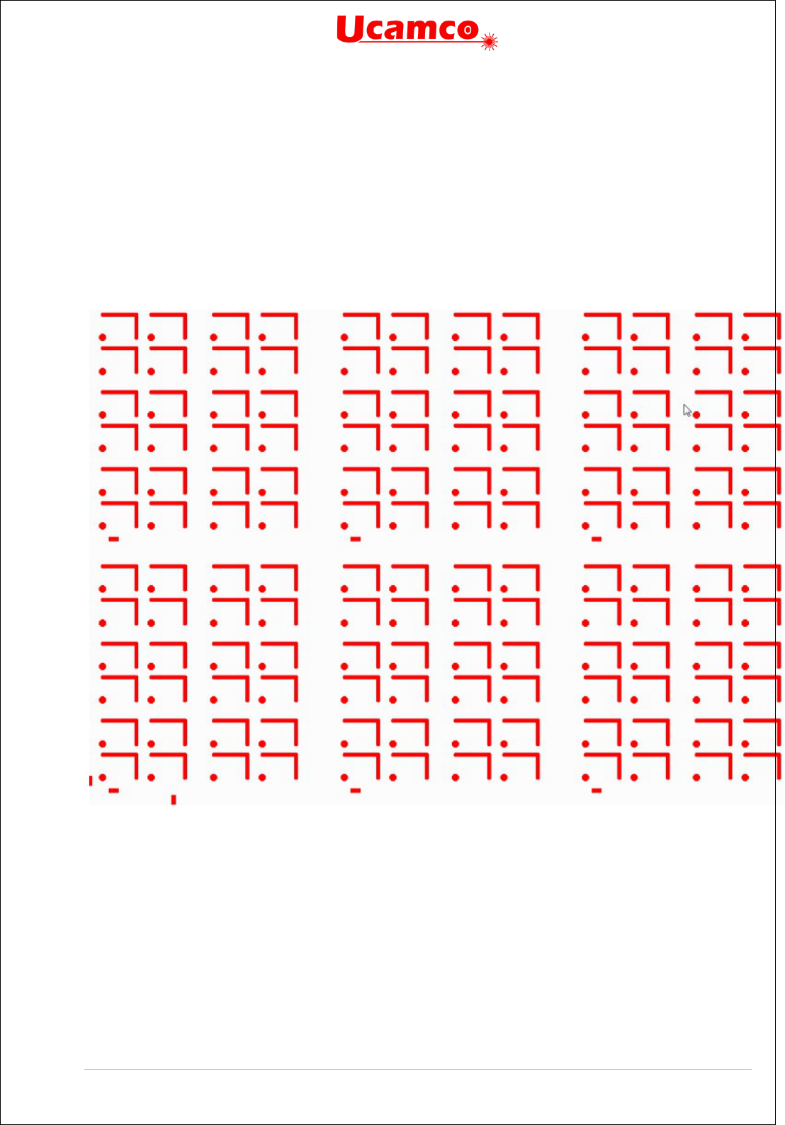
Copyright Ucamco NV 114
Having a question or remark about the spec? Please contact us at gerber@ucamco.com
X143000000Y-30000000D03*
G04 Flash block 102 3x2 times*
D102*
X0Y0D03*
X0Y520000000D03*
X500000000Y0D03*
X500000000Y520000000D03*
X1000000000Y0D03*
X1000000000Y520000000D03*
M02*
45. Block aperture example 1

Copyright Ucamco NV 115
Having a question or remark about the spec? Please contact us at gerber@ucamco.com
4.12 Step and Repeat (SR)
The purpose of the SR command is to replicate a set of graphical objects without replicating
the commands that creates the set.
The SR command %
SRX…Y…I…J…*% opens an SR statement. All subsequent commands are
part of the SR statement until it is closed by an
%SR*%. The parameters X, Y specify the number
of repeats in X and Y and I, J their respective step distances. The graphical objects generated
by the command stream in a SR statement are collected in a block - see 2.8 - instead of being
added directly to the object stream. When the SR command is closed by an
%SR*%, the block is
step-repeated (replicated) in the image plane according to the parameters X, Y, I and J in the
opening SR command. Blocks are copied first in the positive Y direction and then in the positive
X direction. The syntax for the SR command is:
<SR command> = SR[X<Repeats>Y<Repeats>I<Distance>J<Distance>]*
Syntax
Comments
SR
SR for Step and Repeat
X<Repeats> Defines the number of times the block is repeated along the X axis.
<Repeats> is an integer ≥ 1
Y<Repeats> Defines the number of times the block is repeated along the Y axis.
<Repeats> is an integer ≥ 1
I<Distance> Defines the step distance along the X axis.
<Distance> is a decimal number ≥ 0, expressed in the unit of the MO
command
J<Distance> Defines the step distance along the Y axis.
<Distance> is a decimal number ≥ 0, expressed in the unit of the MO
command
Examples:
Syntax
Comments
%SRX2Y3I2.0J3.0*%
Opens an SR statement and starts block accumulation.
When block accumulation is finished the block will be repeated 2 times
along the X axis and 3 times along the Y axis. The step distance
between X-axis repeats is 2.0 units. The step distance between Y-
axis repeats is 3.0 units.
%SRX4Y1I5.0J0*%
Opens an SR statement and starts block accumulation.
When block accumulation is finished the block will be repeated 4 times
along the X axis with the step distance of 5.0 units. The step distance
in the J parameter is ignored because no repeats along the Y axis are
specified.
%SR*%
Closes the SR statement and repeats the previously accumulated
block
The syntax is:

Copyright Ucamco NV 116
Having a question or remark about the spec? Please contact us at gerber@ucamco.com
SR_statement = SR_open {in_block_statement}* SR_close;
SR_open = '%' ('SR' 'X' positive_integer 'Y' positive_integer 'I' decimal 'J'
decimal) '*%';
SR_close = '%' ('SR') '*%';
in_block_statement =
|single_statement
|region_statement
|AB_statement
;
single_statement =
| operation
| interpolation_state_command
| Dnn
| G04
| attribute_command
| AD
| AM
| coordinate_command
| transformation_state_command
;
Example:
G04 A block of two flashes is repeated 3x2 times*
%SRX3Y2I5.0J4.0*%
D13*
X123456Y789012D03*
D14*
X456789Y012345D03*
%SR*%

Copyright Ucamco NV 117
Having a question or remark about the spec? Please contact us at gerber@ucamco.com
46. Blocks replication with SR command
Note that a block contains the graphical objects, not the Gerber source code. The graphical
objects in each copy are always identical, even if the graphics state is modified during the SR
statement.
The current point is undefined after an SR statement.
A file can contain multiple SR statements. The number of steps and the step distances can be
different in X and Y. The number of repeats along an axis can be one; it is then recommended
to use the step distance 0.
A step & repeat block can contain different polarities (LPD and LPC – see 4.9.2
). A clear object
in a block clears all objects beneath it, including objects outside the block. When repeats of
blocks with both dark and clear polarity objects overlap, the step order affects the image; the
correct step order must therefore be respected: step the complete block first in Y and then in X.

Copyright Ucamco NV 118
Having a question or remark about the spec? Please contact us at gerber@ucamco.com
4.13 End-of-file (M02)
The M02 command indicates the end of the file. The syntax is as follows:
M02 = ('M02') '*';
Example:
M02*
The last command in a Gerber file must be the M02 command. No data is allowed after an M02.
Gerber readers are encouraged to give an error on a missing M02 as this is an indication that
the file has been truncated.
Note that a block or region statement must be explicitly closed. Consequently, an M02
command cannot be issued within a block or region statement.

Copyright Ucamco NV 119
Having a question or remark about the spec? Please contact us at gerber@ucamco.com
4.14 Numerical Accuracy
The coordinates of all points and all geometric parameters (e.g. a diameter) have an exact
numerical value. Graphical objects are therefore in principle defined with infinite precision with
the exception of arcs, which are intrinsically slightly fuzzy (see 4.7.2.). A Gerber file specifies an
image with infinite precision.
However, Gerber file writers cannot assume that file readers will process their files with infinite
precision as this is simply impossible. Nemo potest ad impossibile obligari. This raises the
question to what a Gerber file reader is held, and what a Gerber writer can assume.
Visualization
Gerber files are often used to visualize an image on a screen, a photoplotter, a direct imager.
Visualization is unavoidably constrained by the limitations of the output device. Nonetheless,
visualization must comply with the following rules:
Each individual graphical object must be rendered within the stated accuracy of the output
device.
No spurious holes may appear - solid objects must be visualized solid.
No spurious objects may appear.
Zero-size objects are not visualized.
Graphical object can be rendered individually, without considering neighboring objects. In
other words, each graphical object is handled individually, regardless of context.
It is intentionally not specified if rendering must be “fat” or “thin” - fat meaning that features
below the device accuracy are blown up to be visible, thin meaning that they disappear.
These rules have several noteworthy consequences:
Gerber objects separated by a very small gap may touch in the visualized image.
Gerber objects that touch or marginally overlap may be separated by a gap in the
visualized image.
Gerber objects smaller or thinner than the device resolution may totally disappear in the
visualized image.
When what is intended to be a single object is broken down in simpler graphical objects,
and these elementary objects do not sufficiently overlap, the resulting image may not be
solid - it may have internal holes or even break up in pieces. To avoid these effects the best
and most robust approach is not to break up the single object at all: the Gerber format has
powerful primitives to create almost any shape with a single graphical object or possible a
succession of dark and clear objects.
Construct files robustly.
Image Processing
Gerber files are processed for visualization but often also to complex image processing
algorithms: e.g. etch compensation, design rule checks in CAM and so on. These algorithms
perform long sequences of numerical calculations. Rounding errors unavoidably accumulate.
Coordinates can move and object sizes can vary. The specification limits the allowed
perturbation to [-0.5µm, +0.5 µm]; furthermore coincident coordinates must remain coincident.
The writer can assume that the perturbation is within this limit. Higher accuracy cannot be
blindly assumed; if it is needed it must be checked that the applications downstream can handle
this. A file is therefore only robust if, under any allowed perturbation, it remains valid and
represents the same image.

Copyright Ucamco NV 120
Having a question or remark about the spec? Please contact us at gerber@ucamco.com
The perturbation has some noteworthy consequences:
Contours that are not self-intersecting by a margin of ≤1µm can become self-intersecting
under a valid perturbation. Such contours are therefore invalid; see section 4.10.3.
Contours must be constructed robustly so that allowed processing perturbations do not turn
an otherwise valid contour in a self-intersecting one. See 4.14.2. Consequently, points and
segments that are not coincident must be separated by at least 1µm. Furthermore, circular
segments add their own intrinsic fuzziness, see 4.7.2. If any valid interpretation of the arc
violates the requirement of 1µm separation the contour is invalid. Construct contours
defensively. Observe sufficient clearances. Marginal contours can and do lead to problems
Objects that touch or overlap marginally can become separated under perturbation. This is
important for electrical connection. An electrical connection that is realized by touching
objects can get separated by a valid perturbation. Such marginal construction can be validly
interpreted as either isolating or connecting. Make proper and robust electrical connections,
with an overlap of the order of magnitude of at least the minimum conductor width.
Arcs with end points separated by less than 1 µm can toggle between very small or nearly
360 degrees under valid perturbations. Do not write such arcs.
Avoid objects smaller than 1 µm.
Construct files robustly.

Copyright Ucamco NV 121
Having a question or remark about the spec? Please contact us at gerber@ucamco.com
5 Attributes
5.1 Attributes Overview
Attributes add meta-information to a Gerber file. Attributes are akin to labels providing
information about the file or features within them. Examples of meta-information conveyed by
attributes are:
The function of the file in the layer structure. Is the file the top solder mask, the bottom
copper layer, …?
The function of a pad. Is the pad an SMD pad, or a via pad, or a fiducial, ...?
The attribute syntax provides a flexible and standardized way to add meta-information to a
Gerber file, independent of the specific semantics or application.
Attributes do not affect the image. A Gerber reader will generate the correct image if it simply
ignores the attributes.
Each attribute consists of an attribute name and an optional attribute value:
<Attribute> = <AttributeName>[,<AttributeValue>]*
Attribute names follow the name syntax in section 3.4.3.
The attribute value consists of one or more comma-separated fields, see section 3.4.4.
<AttributeValue> = <Field>{,<Field>}
There are three types of attributes by the item they attach to:
Attachment type
The item to which they attach meta-information
File attributes
Attach meta-information to the file as a whole.
Aperture attributes Attach meta-information to an aperture or a region. Objects created by
the aperture inherit the aperture meta-information
Object attributes
Attach meta-information to on object directly
There are two types of attributes by the scope of their use:
Standard attributes. Standard attribute names, values and semantics are defined in this
specification and are part of it. As they are standardized, they can exchange meta-
information between all applications.
User attributes. User attributes can be chosen freely by users to extend the format with
custom meta-information. Use custom attributes only for unequivocally defined
machine-readable information, use G04 for mere human-readable comments.
In accordance with the general rule in 3.4.3 standard attribute names must begin with a dot ‘.’
while user attribute names cannot begin with a dot. The dot, if present, is part of the attribute
name and indicates that it is a standard attribute whose syntax and semantics are defined in
section 5.6.
Example of a user attributes:
%TFMyAttribute,Yes*%
%TFZap*%
%TFZonk*%

Copyright Ucamco NV 122
Having a question or remark about the spec? Please contact us at gerber@ucamco.com
The following commands govern attributes. (They start with a T as the more obvious A is
already taken by the aperture commands.)
Command
Description
Section
TF
Attribute file. Set a file attribute.
5.2
TA Attribute aperture. Add an aperture attribute to the dictionary or
modify it.
5.3
TO Attribute object. Add an object attribute to the dictionary or modify
it.
5.4
TD
Attribute delete. Delete one or all attributes in the dictionary.
5.5
The syntax is as follows:
TF = '%' ('TF' attribute_name {',' attribute_value}*) '*%';
TA = '%' ('TA' attribute_name {',' attribute_value}*) '*%';
TO = '%' ('TO' attribute_name {',' attribute_value}*) '*%';
TD = '%' ('TD' [attribute_name]) '*%';
attribute_name = field;
attribute_value = field;
During the processing of a Gerber file an attribute dictionary is maintained. Dictionary entries
consist of the attribute name, its domain and its value. The attribute name is the key of the
entry; it must consequently be unique, even for attributes with a different domain.
The current aperture dictionary is defined after each command by the following rules:
Initially the attribute dictionary is empty
File attributes are added with the TF command
Aperture attributes are added or updated with the TA command
Object attributes are added or updated with the TO command
Attributes are deleted with the TD command
When an aperture or a graphical object is created all attributes with the proper domain present
in the dictionary at the time of creation are attached to it. They remain fixed and cannot be
changed.
In the following example the command TF defines an attribute with name “.FileFunction” and
value composed of the two fields: “Soldermask,Top”.
Example:
%TF.FileFunction,Soldermask,Top*%
Note that attribute commands are not allowed within a region statement, see 4.10.2.

Copyright Ucamco NV 123
Having a question or remark about the spec? Please contact us at gerber@ucamco.com
5.2 File Attributes (TF)
File attributes provide meta-information about entire files.
The semantics of a file attribute specifies where it must be defined, typically in the header of the
file. A file attribute can only be defined once. It cannot be redefined.
File attributes are set with the uppercase TF command with the following syntax
<TF command> = %TF<AttributeName>[,<AttributeValue>]*%
<AttributeValue> = <Field>{,<Field>}
The attribute name must follow the syntax in section 3.4.3, fields this in 3.4.4. The name is
unique and cannot be used for any other attribute, even of another type.
Example:
%TF.FilePolarity,Negative*%
5.3 Aperture Attributes (TA)
An aperture attribute is attached to an aperture or a region. They are a method to assign
attributes to graphical objects in bulk: all objects that are created with an aperture inherit its
attributes; for example, a via attribute on an aperture means that all pads flashed with this
aperture are via pads. Providing information about graphical objects via their apertures is
elegant, compact and efficient. As region objects are created without intermediary aperture,
aperture objects can be assigned to regions directly.
The TA command adds an aperture attribute into the attributes dictionary. It has the following
syntax:
<TA command> = %TA<AttributeName>[,<AttributeValue>]*%
<AttributeValue> = <Field>{,<Field>}
The attribute name must follow the syntax in section 3.4.3, fields the one in 3.4.4. The name
must be unique. The value of an aperture attribute can be modified by a new TA with the same
attribute name.
The example below defines several attributes.
Example:
%TA.AperFunction,ComponentPad*%
%TAMyApertureAttributeWithValue,value*%
%TAMyApertureAttributeWithoutValue*%
In the next example the aperture value is initially set to ComponentPad and later overruled to
ViaPad.
Example:
%TA.AperFunction,ComponentPad*%
…
%TA.AperFunction,ViaPad*%
When an AD or an AB command creates an aperture all aperture attributes then in the attribute
dictionary are attached to it. Once an aperture is defined its attributes cannot be changed.

Copyright Ucamco NV 124
Having a question or remark about the spec? Please contact us at gerber@ucamco.com
Aperture Attributes on Regions
Counter-intuitively, aperture attributes can be attached to regions. When a G36/G37 creates a
region all aperture attributes in the dictionary are attached to it, in the same way as they are
attached to an aperture created with an AD command. A way to view this is that the G36
command creates a virtual region aperture and attaches attributes to it in the same way as an
AD. Regions effectively function as single-use apertures that are flashed and immediately
forgotten when the region definition is completed.
Aperture attributes on regions are necessary. Aperture attributes are a way to attach properties
to objects such as draws or flashes. It is sometimes necessary to attach the same property to
region objects. For example, the function ‘conductor’ must be assigned both to tracks – draws –
and copper pours – regions. For the tracks this is done with an aperture attribute, a convenient
way to attach an attribute to a larger number of objects. For the regions this is done with the
mechanism in the first paragraph.
Note that aperture attributes are not attached directly to draws, arcs and flashes, because there
it is done indirectly via their aperture.
Example: Define a copper pour as a region
%TA.AperFunction,Conductor*%
G36*
X118151529Y-78573554D02*
G01*
X118230607Y-78626393D01*
X118283446Y-78705471D01*
X118302000Y-78798750D01*
X118302000Y-79286250D01*
…
X118151529Y-78573554D01*
G37*
For the avoidance of doubt: regions take the aperture attributes from the dictionary, not from the
current aperture.
5.4 Object Attributes (TO)
An object attribute is attached to graphical objects. When a D01, D03 or region statement
(G36/G37) creates an object all object attributes in the attribute dictionary are attached to it. As
attribute commands are not allowed inside a region statement, all regions created by that
statement have the same object attributes. Once attached to an object they cannot be changed.
The TO command adds an object attribute into the attributes dictionary. It has the same syntax
as the TF command:
<TO command> = %TO<AttributeName>[,<AttributeValue>]*%
<AttributeValue> = <Field>{,<Field>}
The attribute name must follow the syntax in section 3.4.3, fields the one in 3.4.4. The name is
unique and cannot be used for any other attribute, even of another type. The value of an object
attribute can be modified by a new TO command with the same attribute name.
Example:
%TO.C,R6*%

Copyright Ucamco NV 125
Having a question or remark about the spec? Please contact us at gerber@ucamco.com
5.5 Delete Attribute (TD)
The TD command deletes an attribute from the attributes dictionary. Note that the attribute
remains attached to apertures and objects to which it was attached before it was deleted.
<TD command> = %TD[<AttributeName>]*%
The <AttributeName> is the name of the attribute to delete. If omitted, the whole dictionary is
cleared.

Copyright Ucamco NV 126
Having a question or remark about the spec? Please contact us at gerber@ucamco.com
5.6 Standard Attributes
Overview
Name Usage Section Attached
to
.Part
Identifies the part the file represents, e.g. a
single PCB
5.6.2 File
.FileFunction
Identifies the file’s function in the PCB, e.g. top
copper layer
5.6.3 File
.FilePolarity
Positive or Negative. This defines whether
the image represents the presence or
absence of material.
5.6.4 File
.SameCoordinates
All files in a fabrication data set with this
attribute use the same coordinates. In other
words, they align.
5.6.5 File
.CreationDate
Defines the creation date and time of the
file.
5.6.6 File
.GenerationSoftware
Identifies the software creating the file.
5.6.7
File
.ProjectId
Defines project and revisions.
5.6.8
File
.MD5
Sets the MD5 file signature or checksum.
5.6.9
File
.AperFunction
Function objects created with the apertures,
e.g. SMD pad
5.6.10 Aperture
.DrillTolerance
Tolerance of drill holes
5.6.11
Aperture
.FlashText
If a flash represents text allows to define
string, font, …
5.6.12 Aperture
.N
The CAD net name of a conducting object,
e.g. Clk13.
5.6.13 Graphical
object
.P
The pin number (or name) and reference
descriptor of a component pad on an outer
layer, e.g. IC3,7.
5.6.14 Graphical
object
.C
The component reference designator linked
to an object, e.g C2.
5.6.15 Graphical
object
Table with the standard attributes
Attributes are not needed when the image only needs to be rendered. However, attributes are
needed in PCB fabrication data, when transferring PCB data from design to fabrication. For
example, the fabricator needs to know what are the via pads to handle the solder mask
properly. The standard attributes transfer the design intent from CAD to CAM in an unequivocal

Copyright Ucamco NV 127
Having a question or remark about the spec? Please contact us at gerber@ucamco.com
and standardized manner. This is sometimes rather grandly called “adding intelligence to the
image”. Without standard attributes the design intent must be gathered from various documents,
unwritten rules, conversations or reverse engineering, with all the risks of error and delay that
this entails.
It is strongly recommended to use standard attributes as comprehensively as possible. If you
cannot provide all the attributes or are unsure of their use then provide all the attributes you are
comfortable with. Partial information is better than no information. For professional PCB
production the bare minimum is to set .FileFunction and .FilePolarity.
Note that standard attribute values typically contain a value “Other” to cater to requirements not
yet foreseen in the specification. The intention is to add new values as the need arises to
reduce the use of “Other” over time.
We are open to your suggestions for new generally useful attributes. Please contact Ucamco at
to request it. Authors will be properly acknowledged when their
suggestions are included in the standard.
Warning: Do not invent your own standard attribute names (names starting with a dot).
This would defeat the purpose of standardization. User attributes cater to specific needs that are
not covered by the standard attributes. Feel free to invent any user attribute you wish.

Copyright Ucamco NV 128
Having a question or remark about the spec? Please contact us at gerber@ucamco.com
.Part
The value of the .Part file attribute identifies which part is described. The attribute – if present -
must be defined in the header.
.Part value
Usage
Single
Single PCB
Array
A.k.a. customer panel, assembly panel, shipping panel,
biscuit
FabricationPanel
A.k.a. working panel, production panel
Coupon
A test coupon
Other,<mandatory
field>
None of the above. The mandatory field informally
indicates the part
.Part file attribute values
Example:
%TF.Part,Array*%

Copyright Ucamco NV 129
Having a question or remark about the spec? Please contact us at gerber@ucamco.com
.FileFunction
The .FileFunction file attribute identifies the function of the file in the PCB layer structure. Of all
the attributes it is the most important.
Example:
%TF.FileFunction,Copper,L1,Top*%
The attribute must be defined in the header.
The existence of a file function does not mean that it must be included in each PCB fabrication
data sets. Include the files that are needed: no more, no less.
The file functions are designed to support all file types in current use. If a type you need is
missing please contact us at [email protected].
.FileFunction value
Usage
Data files
Copper,L<p>,(Top|Inr|Bot)[,<type>]
A conductor or copper layer.
L<p> (p is an integer>0) specifies the physical
copper layer number. Numbers are
consecutive. The top layer is always L1. (L0
does not exist.) The mandatory field
(Top|Inr|Bot) specifies it as the top, an inner or
the bottom layer; this redundant information
helps in handling partial data. The specification
of the top layer is “
Copper,L1,Top[,type]”,
of the bottom layer of an 8 layer job it is
Copper,L8,Bot[,type]
The top side is the one with the through-hole
components, if any.
The optional <type> field indicates the layer
type. If present it must take one of the following
values: Plane, Signal, Mixed or Hatched.
Plated,i,j,(PTH|Blind|Buried)
[,<label>]
Plated drill/rout data, span from copper layer i
to layer j. The from/to order is not significant.
The (PTH|Blind|Buried) field is mandatory.
The label is optional. If present it must take one
of the following values: Drill, Rout or Mixed.
NonPlated,i,j,(NPTH|Blind|Buried)
[,<label>]
Non-plated drill/rout data, span from copper
layer i to layer j. The from/to order is not
significant. The (NPTH|Blind|Buried) field is
mandatory.
The label is optional. If present it must take one
of the following values: Drill, Rout or Mixed.

Copyright Ucamco NV 130
Having a question or remark about the spec? Please contact us at gerber@ucamco.com
.FileFunction value
Usage
Profile,(P|NP)
A file containing the board profile (or outline)
and only the board profile. Such a file is
mandatory in a PCB fabrication data set. See
6.5.
The mandatory (P|NP) label indicates whether
board is edge-plated or not.
Soldermask,(Top|Bot)[,<index>]
Solder mask or solder resist.
Usually the image represents the solder mask
openings; it then has negative polarity, see
5.6.4.
The optional field is only needed when there is
more than one solder mask on one side – top
or bottom. The integer <index> then numbers
the solder masks from the PCB side outwards,
starting with 1 for the mask directly on the
copper. Usually there is only one solder mask
on a side, and then <index> is omitted. An
example with two top solder masks:
Soldermask,Top,1 Mask on the copper
Soldermask,Top,2 Mask on the first
mask
Legend,(Top|Bot)[,<index>]
A legend is printed on top of the solder mask to
show which component goes where. A.k.a.
‘silk’ or ‘silkscreen’.
See the Soldermask entry for an explanation of
the index.
Component,L<p>,(Top|Bot)
A layer with component information.
L<p> The integer p is the copper layer number
to which the components described in this file
are attached. (Top|Bot) indicates if the
components are on top, upwards, or on the
bottom, downward, of the layer to which they
are attached. This syntax caters for embedded
components.
For jobs without embedded components there
is an intentional redundancy.
Paste,(Top|Bot)
Locations where solder paste must be applied.
Glue,(Top|Bot)
Glue spots used to fix components to the board
prior to soldering.
Carbonmask,(Top|Bot)[,<index>]
See Soldermask for the usage of <index>.
Goldmask,(Top|Bot)[,<index>]
See Soldermask for the usage of <index>.

Copyright Ucamco NV 131
Having a question or remark about the spec? Please contact us at gerber@ucamco.com
.FileFunction value
Usage
Heatsinkmask,(Top|Bot)[,<index>]
See Soldermask for the usage of <index>.
Peelablemask,(Top|Bot)[,<index>]
See Soldermask for the usage of <index>.
Silvermask,(Top|Bot)[,<index>]
See Soldermask for the usage of <index>.
Tinmask,(Top|Bot)[,<index>]
See Soldermask for the usage of <index>.
Depthrout,(Top|Bot)
Area that must be routed to a given depth
rather than going through the whole board.
Vcut[,(Top|Bot)]
Contains the lines that must be v-cut. (V-
cutting is also called scoring.)
If the optional attachment (Top|Bot) is not
present the scoring lines are identical on top
and bottom – this is the normal case. In the
exceptional case scoring is different on top and
bottom two files must be supplied, one with
Top and the other with Bot.
Viafill
Contains the via’s that must be filled. It is
however recommended to specify the filled
via’s with the optional field in the .AperFunction
ViaDrill.
Drawing files
Drillmap
A drawing with the locations of the drilled
holes. It often also contains the hole sizes,
tolerances and plated/non-plated info.
FabricationDrawing
A auxiliary drawing with additional information
for the fabrication of the bare PCB: the location
of holes and slots, the board outline, sizes and
tolerances, layer stack, material, finish choice,
etc.
Vcutmap
A drawing with v-cut or scoring information.
AssemblyDrawing,(Top|Bot)
An auxiliary drawing with the locations and
reference designators of the components. It is
mainly used in PCB assembly.
ArrayDrawing
A drawing of the array (biscuit, assembly
panel, shipment panel, customer panel).
OtherDrawing,<mandatory field>
Any other drawing than the five ones above.
The mandatory field informally describes its
topic.

Copyright Ucamco NV 132
Having a question or remark about the spec? Please contact us at gerber@ucamco.com
Other files
Pads,(Top|Bot)
A file containing only the pads (SMD, BGA,
component, …). Not needed in a fabrication
data set.
Other,<mandatory field>
The value ‘Other’ is to be used if none of the
values above fits. By putting ‘Other’ rather than
simply omitting the file function attribute it is
clear the file has none of the standard
functions, already useful information. Do not
abuse standard values for a file with a vaguely
similar function – use ‘Other’ to keep the
function value clean and reliable.
The mandatory field informally describes the
file function.
.FileFunction attribute values
Examples. File functions of a four layer board (One for each Gerber file):
%TF.FileFunction,Legend,Top*%
%TF.FileFunction,Soldermask,Top*%
%TF.FileFunction,Copper,L1,Top*%
%TF.FileFunction,Copper,L2,Inr,Plane*%
%TF.FileFunction,Copper,L3,Inr,Plane*%
%TF.FileFunction,Copper,L4,Bot*%
%TF.FileFunction,Soldermask,Bot*%
%TF.FileFunction,NonPlated,1,4,NPTH,Drill*%
%TF.FileFunction,NonPlated,1,4,NPTH,Rout*%
%TF.FileFunction,Plated,1,4,PTH*%
%TF.FileFunction,Profile,NP*%
%TF.FileFunction,Drillmap*%

Copyright Ucamco NV 133
Having a question or remark about the spec? Please contact us at gerber@ucamco.com
.FilePolarity
The .FilePolarity specifies whether the image represents the presence or absence of material.
The .FilePolarity attribute does not change the image - no attribute does. It changes the
interpretation of the image. For example, in a copper layer in positive polarity a round flash
generates a copper pad. In a copper layer in negative polarity it generates a clearance.
The attribute must be defined in the header.
Warning: Solder mask images nearly always represent the solder mask openings and are
therefore negative. This may be counter-intuitive.
Drill and rout files represent the removed material. Drill files are therefore positive, as is intuitive.
.FilePolarity value
Usage
Positive
The image represents the presence of material
(recommended)
Negative
The image represents the absence of material
.FilePolarity attribute values
Example:
%TF.FileFunction,Copper,L2,Inr,Plane*%
%TF.FilePolarity,Positive*%
Note: It is recommended output copper layers in positive. Power/ground planes in negative
was introduced in the 1970s and 1980s to get around the limitations in the vector photoplotters
then used. There is no longer any reason to use them, and they have a problem: they cannot
not define how close the copper gets to the outline of the PCB. See 4.10.5 in how to create
power/ground planes in positive. But if you need to output negative copper layers, make it clear
they are negative by setting the .FilePolarity attribute.

Copyright Ucamco NV 134
Having a question or remark about the spec? Please contact us at gerber@ucamco.com
.SameCoordinates
All layers in a PCB fabrication data set- a folder or archive - must use the same coordinate
system. In other words, they must align or register as the layers in the physical PCB do. For
example, the pads, drill holes, pads and solder mask openings of a pad stack must all have the
same coordinates.
Layers must not be offset, mirrored of flipped versus one another. This may seem obvious but
unfortunately layers do not align in 1/3 of the data sets. The fabricator consequently cannot trust
the alignment of the incoming data. This uncertainty interferes with fast and automatic
processing; worse, it can lead to scrap with boards where wrong alignment is not obvious, such
as very symmetric HF boards.
The .SameCoordinates attribute tells the fabricator that the alignment is correct.
The attribute must be defined in the header. The syntax is as follows:
%TF.SameCoordinates[,<ident>]*%
Example – without ident:
%TF.SameCoordinates*%
If this attribute is present in a number of Gerber files in a PCB fabrication data set then
these files are in alignment with each other.
Example – with a GUID as ident:
%TF.SameCoordinates,f81d4fae-7dec-11d0-a765-00a0c91e6bf6*%
The ident is optional. Its purpose is the following. There may be situations where files in the
fabrication data are output at different times, with different coordinate systems. In that
situation simply outputting the attribute would wrongly signal the layers do align. Adding the
ident avoids this error by distinguish between these different coordinate systems at output
time. If the attribute with the same ident is present in a number of Gerber files then they
align. If the ident is different they may not align – which would be an error because all files
must align. For the fabricator the only important fact is whether the ident, if present, are
identical or not; otherwise the ident has no meaning. A very safe ident is a GUID. When all
files are output at the same time, with the same coordinates, the ident is not needed.
Note that all data files must align anyhow, attribute or no attribute.
.CreationDate
The .CreationDate file attribute identifies the moment of creation of the Gerber file.
The attribute – if present - must be defined in the header. The attribute value must conform to
the full version of the ISO 8601 date and time format, including the time zone. A formally defined
creation date can be helpful in tracking revisions – see also 5.6.8
Example:
%TF.CreationDate,2015-02-23T15:59:51+01:00*%

Copyright Ucamco NV 135
Having a question or remark about the spec? Please contact us at gerber@ucamco.com
.GenerationSoftware
The .GenerationSoftware file attribute identifies the software that generated the Gerber file. The
field <vendor> identifies the organization that supplies the generating software to its users; this
can be a commercial company, an open source organization, etc.
The attribute – if present - must be defined in the header. The syntax is as follows:
%TF.GenerationSoftware,<vendor>,<application>[,<version>]*%
Example:
%TF.GenerationSoftware,Ucamco,UcamX,2017.04*%
.ProjectId
Usually a Gerber file is part of a PCB project with a sequence of revisions. The purpose of the
.ProjectId file attribute is to uniquely identify project and revision. This is especially important to
check whether all files belong to the same revision. By its nature, these values can only be
defined by the creator of the project and revision.
The attribute – if present - must be defined in the header. The syntax is as follows:
%TF.ProjectId,<Name>,<GUID>,<Revision>*%
The field <Name> is the id or reference used by the design owner, <GUID> defines the project
using a global unique ID and <Revision> specifies its revision. All parameters must conform to
the field syntax, see 3.4.4. The <GUID> is a field conforming to RFC4122 version 1 or version 4.
Examples:
%TF.ProjectId,My PCB,f81d4fae-7dec-11d0-a765-00a0c91e6bf6,2*%
%TF.ProjectId,project#8,68753a44-4D6F-1226-9C60-0050E4C00067,/main/18*%

Copyright Ucamco NV 136
Having a question or remark about the spec? Please contact us at gerber@ucamco.com
.MD5
The .MD5 file attribute sets a file signature (checksum, hash, digest) that uniquely identifies the
file and provides a high degree of security against accidental modifications.
The .MD5 checksum is not intended for CAD to CAM data transfer which is probably sufficiently
protected by the checksum of the zip, but rather for individual files used within fabrication, with a
bewildering collection of legacy systems and protocols, and where file transmission errors
sometimes occur.
The 128 bit signature is calculated with the MD5 algorithm and expressed as a 32 digit
hexadecimal number (see Error! Reference source not found.). The signature is calculated
over the bits from the beginning of the file up to but excluding the .MD5 file attribute command.
Note that this excludes the closing M02*. The complete .MD5 file attribute command, with both
‘%’and ‘*’, is excluded. Any CR and LF are excluded from signature calculation. As CR and LF
do not affect the interpretation of the file but may be altered when moving platforms excluding
them makes the signature portable without sacrificing security.
The signature, if present, must be put at the end of the file, just before the closing M02*. Thus
the file can be processed in a single pass.
Example:
Consider the following Gerber file segment, without checksum:
…
D11*
X1500000Y2875000D03*
X2000000D03*
D19*
X2875000Y2875000D03*
M02*
As the CR and LF characters are skipped the checksum is taken over the following data:
…D11*X1500000Y2875000D03*X2000000D03*D19*X2875000Y2875000D03*
With the checksum the file then becomes:
…
D11*
X1500000Y2875000D03*
X2000000D03*
D19*
X2875000Y2875000D03*
%TF.MD5,6ab9e892830469cdff7e3e346331d404*% <- Excluded from the MD5
M02* <- Excluded from the MD5

Copyright Ucamco NV 137
Having a question or remark about the spec? Please contact us at gerber@ucamco.com
The following Perl script specifies precisely how the .MD5 is calculated:
#script expects one parameter (original Gerber X2 file)
use Digest::MD5;
local $_ = shift;
local *IN;
my $content;
local $/;
open(IN, "<$_") or die "Cannot open $_ due to $!";
$content = <IN>; #read file to the variable
close IN;
$content =~ s/\r|\n//g; #remove all CRLF (end of line) characters
$content =~ s/M02\*//; #remove M02 from the end of file
#calculate MD5
$md5 = Digest::MD5->new; #init MD5
$md5->add($content); #send content of the file to MD5 engine
print "Add 2 following lines to the Gerber file, please.\n";
print "%TF.MD5,";
print $md5->hexdigest; #print correct MD5 hash
print "*%\nM02*\n\n";

Copyright Ucamco NV 138
Having a question or remark about the spec? Please contact us at gerber@ucamco.com
.AperFunction
The .AperFunction aperture attribute defines the function or purpose of an aperture, or rather
the graphical objects created with it. PCB CAM needs to know the function of graphical objects,
especially pads. If this is not possible define the function of all attributes then at least define if
for those where you can - partial information is better than no information. The bare minimum is
to identify via pads: the PCB fabricator must know where the via pads are.
One function, one aperture. Objects with different functions must have different apertures,
even if they are of the same shape and size. Apertures with multiple functions are devilishly
hard to handle in CAM to start with: the CAM operator can no longer perform functions per
aperture, but must check each individual hole. Furthermore, their functions cannot be identified
by an aperture attribute: all objects created with it have the same function. This also applies to
drill tools: e.g. if the same diameter is used for component holes and via holes, these still must
be separate apertures. It is recommended to also use different apertures for drill holes and rout
slots.
Regions. Counterintuitively, regions can carry aperture attributes, see 5.3.1. Use .AperFunction
to define the function of the regions.
Painting (aka vector-fill).
It is strongly recommended not to use painting, see 7.2. If you still construct objects by painting,
the function of the painted object is set by the function of apertures used for painting. For
example, if aperture 21 is used to paint SMD pads then the function of aperture 21 is SMDPad.
If aperture 50 is used to paint a conductive region then the function of aperture 50 is conductor.
The .AperFunction values are defined in the tables below. Note that the attribute values typically
can only be applied to specific layers - for example, an SMD pad can only be defined on an
outer copper layer.
Drill and rout files
Note that these values can apply to drill holes and rout slots.
.AperFunction value
Usage
ViaDrill[,
<IPC-4761>
]
<IPC-4761>=(Ia|Ib|IIa|IIb|
IIIa|IIIb|IVa|IVb|V|VI|
VII|None)
A via hole. This is reserved for holes whose sole
function is to connect different layers. It is not to be
used for holes for component leads. No pins will be
pushed in via holes.
An optional field specifies the via protection according
to IPC-4761
BackDrill
A hole to remove plating over a sub-span by drilling that
sub-span with a larger diameter.
ComponentDrill
[,PressFit]
A hole that is used for the attachment and/or electrical
connection of component terminations, including pins
and wires, to a printed board. (Per IPC-T-50).
The optional label PressFit indicates drill holes for press
fit leads. Press fit leads are pressed in properly sized
plated-through holes to realize the electrical contact.
The label can only be applied on PTH holes.
See also ComponentPad.
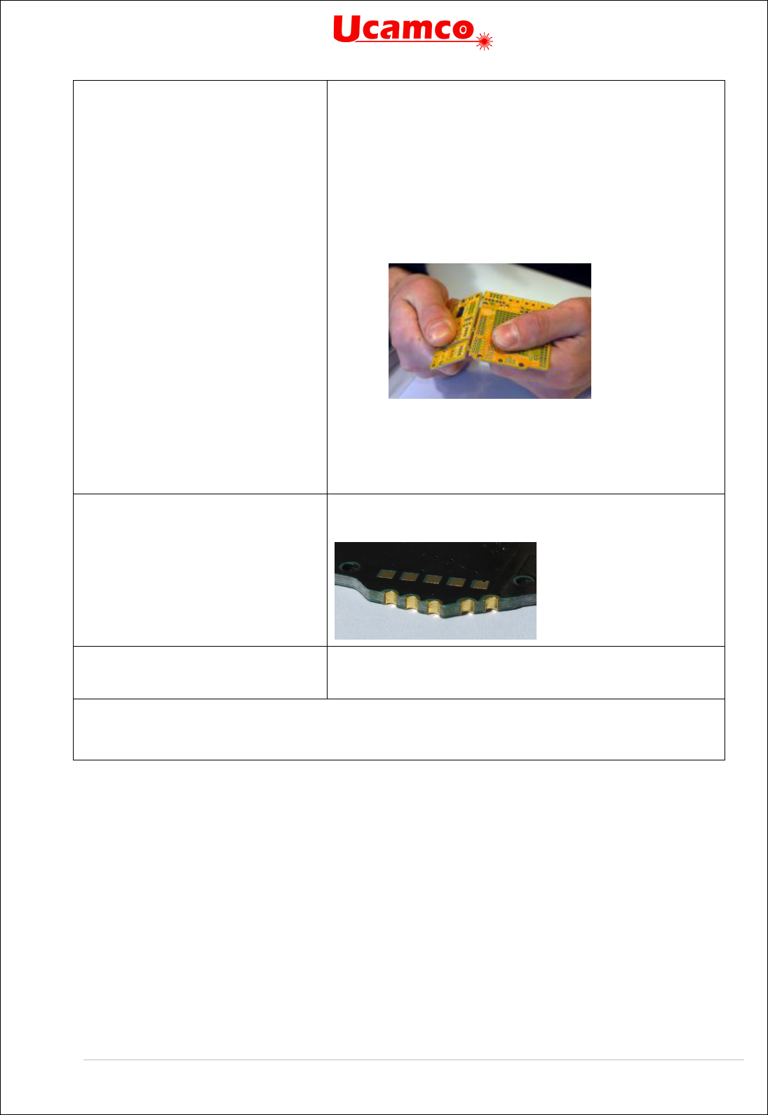
Copyright Ucamco NV 139
Having a question or remark about the spec? Please contact us at gerber@ucamco.com
MechanicalDrill
[,(Tooling|Breakout|Other)]
A hole with mechanical function (registration, screw,
etc.) The specifier is optional. If present it can take one
of the following values:
• Tooling: Tooling holes to attach the board or
panel temporarily to test fixtures during
assembly and test. Also called mounting holes.
• BreakOut: Non-plated holes forming a break-
out tab used in break routing.
• Other
Example:
.AperFunction,MechanicalDrill,Breakout
.AperFunction,MechanicalDrill
CastellatedDrill
Plated holes cut- through by the board edge; used to
join PCBs.
Image courtesy Eurocircuits.
OtherDrill,<mandatory field>
A hole, but none of the above. The mandatory field
informally describes the type.
The values in All layers
can also be used

Copyright Ucamco NV 140
Having a question or remark about the spec? Please contact us at gerber@ucamco.com
Copper layers
.AperFunction value
Usage
ComponentPad
A pad associated with a component hole. The pads
around a ComponentDrill on all layers take the value
ComponentPad although indeed on inner layers they
only have a via function. In other words, the pad
attribute value follows the drill tool attribute value.
Only for through-hole components; SMD and BGA
which have their own dedicated type.
See also ComponentDrill.
SMDPad,(CuDef|SMDef)
A pad belonging to the footprint of an SMD component.
They are pasted or otherwise electrically connected to
the PCB. The purpose of these pads is normally to
connect the component circuitry to the PCB but for
specific components some pads may not connected to
the component inside the package. Excludes BGA pads
which have their own type. This function is valid only for
the normal electrical pads, thermal pads have their own
function; see HeatsinkPad.
The specifier (CuDef|SMDef) is mandatory. CuDef
stands for copper defined; it is by far the most common
SMD pad; the copper pad is completely free of solder
mask; the area to be covered by solder paste is defined
by the copper pad. SMDef stand for solder mask
defined; the solder mask overlaps the copper pad; the
area to be covered by solder paste is defined by the
solder mask opening and not by the copper pad.
(CuDef is sometimes rather awkwardly called non
solder mask defined.)
Only applicable for outer layers.
When an SMD pad contains a via hole the pad where
the SMD is soldered, on the outer layer with the SMD,
is SMDPad, all other pads in the stack are ViaPad. If
the SMD pad contains an embedded via pad, as it
should, then that embedded pad is of course ViaPad.

Copyright Ucamco NV 141
Having a question or remark about the spec? Please contact us at gerber@ucamco.com
BGAPad,(CuDef|SMDef)
A pad belonging to the footprint of an BGA component.
They are soldered or otherwise electrically connected to
the PCB. The purpose of these pads is normally to
connect the component circuitry to the PCB but for
specific components some pads may not connected to
the component inside the package.
The specifier (CuDef|SMDef) is mandatory. CuDef
stands for copper defined, SMDef for solder mask
defined; see SMDPad.
Only applicable for outer layers.
When a BGA pad contains a via hole the pad where the
BGA is soldered is BGAPad, all other pads in the stack
are ViaPad. If the BGA pad contains an embedded via
pad, as it should, then that embedded pad is of course
ViaPad.
ConnectorPad
An edge connector pad.
Only applicable for outer layers.
HeatsinkPad
Heat sink or thermal pad, typically for SMDs
ViaPad
A via pad. It provides a ring to attach the plating in the
barrel. This is reserved for pads that have no other
function than making the connection between layers:
Component pads often also have a via function;
however their main function is component pad and they
must have this function; similar for test pads, via in BGA
etc.
TestPad
A test pad. Only applicable for outer layers.
Sometimes a test pad is drilled and also has a via
function, to save space. Such a pad must be specified
as test pad. (It is clear from the construction that it has
a via function, but the fabricator must know it is a test
pad, and this is not obvious. Similarly, a component pad
can also function as a via, but it remains a component
pad.)
CastellatedPad
Pads on plated holes cut- through by the board edge;
used to join PCBs.
Image courtesy Eurocircuits.

Copyright Ucamco NV 142
Having a question or remark about the spec? Please contact us at gerber@ucamco.com
FiducialPad
,(Local|Global|Panel)
A fiducial pad.
The specifier (Local|GlobalPanel) is mandatory. Local
fiducials pads are used to locate the position of an
individual component, global to locate a single PCB,
and Panel to locate a panel.
ThermalReliefPad
A thermal relief pad connected to the surrounding
copper while restricting heat flow.
WasherPad
A pad around a non-plated hole without electrical
function. Several applications, e.g. a pad that
strengthens the PCB where fixed with a bolt – hence
the name washer.
AntiPad
A pad with clearing polarity (LPC) creating a clearance
in a plane. It makes room for a drill pass without
connecting to the plane. Note that setting the AntiPad
attribute itself has no effect on the image, and therefore
does not turn the pad into LPC as a side effect– this
must be done explicitly by an %LPC*% command.
OtherPad,<mandatory field>
A pad not specified above. The mandatory field
informally describes the type.
Conductor
Copper whose function is to connect pads or to provide
shielding, typically tracks and copper pours such as
power and ground planes. Note that conductive copper
pours should carry this attribute, whether made properly
by a region statement or by painting – see Regions.
(Note that painting is poor practice, but if you have to
paint, at least add the attribute so that it is clear what
the tangle of draws mean.)
EtchedComponent
Etched components are embedded inductors,
transformers and capacitors which are etched into the
PCB copper. The following illustration shows two
etched inductors:
For the CAD netlist these are components like others:
the net names are different on both sides. (However, for
bare-board electrical test they may be conducting
copper and connect the net on both sides.)

Copyright Ucamco NV 143
Having a question or remark about the spec? Please contact us at gerber@ucamco.com
NonConductor
Copper that does not serve as a conductor, that has no
electrical function; typically text in the PCB such as a
part number and version. Not that this attribute can
only be applied to copper, not to drawing elements in a
copper layer; see also NonMaterial and Profile.
CopperBalancing
Copper pattern added to balance copper coverage for
the plating process.
Border
The copper border of a production panel.
OtherCopper,<mandatory
field>
Indicates another function. The mandatory field
informally describes the type.
The values in All layers
can also be used

Copyright Ucamco NV 144
Having a question or remark about the spec? Please contact us at gerber@ucamco.com
Component Layers
.AperFunction value
Usage
ComponentMain
This aperture is flashed at the centroid of a component.
The flash carries the object attributes with the main
characteristics of the component.
The following aperture must be used:
%ADDnnC,0.300*% (mm)
%ADDnnC,0.012*% (in)
nn is an aperture number, an integer ≥ 10.
ComponentOutline,<type>
<type>=(Body|Lead2Lead|
Footprint|Courtyard)
This attribute is used to draw the outline of the component.
An outline is a sequence of connected draws and arcs.
They are said to connect only if they are defined
consecutively, with the second starting where the first one
ends. Thus, the order in which they are defined is
significant. A contour is closed: the end point of the last
draw/arc must coincide with the start point of the first.
Outlines cannot self-intersect.
Four different types of outlines are defined. See drawing,
courtesy Thiadmer Riemersma:
Outlines of different types on the same component are
allowed. The following aperture must be used:
%ADDnnC,0.100*% (mm)
%ADDnnC,0.004*% (in)
ComponentPin
The coordinates in the flash command (D03) indicate the
location of the component pins (leads). The .P object
attribute must be attached to each flash to identify the
reference descriptor and pin.
For the key pin, typically pin "1" or "A1", the following
diamond shape aperture must be used:
%ADDnnP,0.360X4X0.0*% (mm)
%ADDnnP,0.017X4X0.0*% (in)
The key pin is then visible in the image.
For all other pins the following zero size aperture must be
used:
%ADDnnC,0*%...(both mm and in)
These pins are not visible which avoids cluttering the
image.
The values in All layers
can also be used


Copyright Ucamco NV 146
Having a question or remark about the spec? Please contact us at gerber@ucamco.com
All layers
The values in this table can be used on all layers, including plated, non-plated and copper.
.AperFunction value
Usage
Profile
Identifies the draws and arcs that exactly define the
profile or outline of the PCB. This is the content of the
Profile file but can also be present in other layers. See
6.5
NonMaterial
The attribute value NonMaterial identifies objects that do
not represent physical material but drawing elements.
NonMaterial is only meaningful on files that define the
pattern of physical layers of a PCB such as copper layers
or solder mask. Such files unfortunately sometimes not
only contain data representing material but also drawing
elements such as a frame and a title block. (Note:
drawing elements should not be mixed with pattern data,
all, see 6.6.1.2. Use drawing files for drawings.).
Material
Identifies the proper part of the data file.
Solder masks are traditionally negative. The image
represents the solder mask openings. The apertures take
the value ‘Material’ – they define solder mask material,
but in a negative way.
For copper and drill layers Material is split into more
specific functions such as SMD pad. Use the specific
functions when available rather than ‘Material’.
Other,<mandatory field>
The value ‘Other’ is to be used if none of the values
above fits. By putting the value ‘Other’ rather than crudely
omitting the attribute it is made explicit that the value is
none of the above – an omitted attribute can be one of
the above. Certainly do not abuse existing values by
horseshoeing an attribute with a vaguely similar function
into that value that does not fit perfectly – keep the
identification clean by using ‘Other’.
The mandatory field informally describes the aperture
function.
.AperFunction aperture attribute values

Copyright Ucamco NV 147
Having a question or remark about the spec? Please contact us at gerber@ucamco.com
Functions on extra layers. The solder mask, paste and other extra layers openings cannot
take the pad values. Pad values are reserved for outer copper layers. The solder mask
openings and paste pads take their function from the underlying copper pads. The reason for
this is that a single solder mask opening may have multiple underlying copper pads – e.g. an
SMP pad with an embedded via pad - and hence multiple functions.
Consequently, solder mask openings have the aperture function ‘Material’. Admittedly this is
somewhat a misnomer in this context as solder masks are usually negative, and the presence
of image indicates therefore the absence of material; this has nothing to do with the pad
functions but with the layer being negative.
The following file creates a circular hole in the solder mask. In negative file polarity the image
represents the absence of material.
%FSLAX36Y36*%
%MOMM*%
%TF.FileFunction,Soldermask,Top*%
%TF.Part,Single*%
%TF.FilePolarity,Negative*%
%TA.AperFunction,Material*%
%ADD10C,2.54*%
%LPD*%
D10*
X123500000Y12500D0003*
...
M02*
If the file polarity is positive an otherwise identical file creates a circle consisting of solder mask.
%FSLAX36Y36*%
%MOMM*%
%TF.FileFunction,Soldermask,Top*%
%TF.Part,Single*%
%TF.FilePolarity,Positive*%
%TA.AperFunction,Material*%
%ADD10C,2.54*%
%LPD*%
D10*
X123500000Y125000000D03*
...
M02*

Copyright Ucamco NV 148
Having a question or remark about the spec? Please contact us at gerber@ucamco.com
.DrillTolerance
.DrillTolerance defines the plus and minus tolerance of a drill hole end diameter. Both values
are positive decimals expressed in the MO units. The attribute value has the following syntax:
<plus tolerance>,<minus tolerance>
Examples:
%TA.DrillTolerance,0.01,0.005*%
.FlashText
Gerber intentionally does not contain fonts or typographic text – this would introduce a
complexity out of proportion to its benefits. Any text can be represented with the available
graphic constructs, especially with contours. However, such generic graphic constructs do not
maintain the information which text string is represented; this is sometimes a disadvantage.
The .FlashText aperture attribute transfers this otherwise lost information. .FlashText is
designed for text image created with a flash. If the text is created with draws and arcs rather
than a flash, it can always be flashed by collecting them in a block aperture.
Bar codes are handled as text – one can view a barcode as a special font.
The syntax and semantic of the attribute value is as follows:
<Text>,(B|C),[(R|M)],[<Font>],[Size],[<Comment>]
.FlashText fields
Usage
<text>
The text string represented by the aperture image.
(B|C)
Indicates if the text is represented by a barcode – B -or
by characters - C.
(R|M)
Indicates if the text is readable or mirrored left-right .
Optional.
<Font>
Font name. Content not standardized. Optional.
<Size>
Font size. Content not standardized. Optional.
<Comments>
Any extra information one wants to add. Optional.
An empty field means that the corresponding meta-data is not specified.
Examples:
%TA.FlashText,L1,C,R,Courier,10,Layer number (L1 is top)*%
Text: L1
B|C: Characters,
(R|M): Readable
Font: Courier
Size: 10
Comment: Layer number (L1 is top)
%TA.FlashText,XZ12ADF,B,,Code128,,Project identifier *%
Text: XZ12ADF
B|C: Barcode
(R|M) Not specified
Font: Code128

Copyright Ucamco NV 149
Having a question or remark about the spec? Please contact us at gerber@ucamco.com
Size: Not specified
Comment: Project identifier
.N (Net)
The .N object attribute attaches a CAD netlist name to any conducting object. The attribute can
be attached to objects on any copper layer or plated drill/rout file. It indicates the object is part of
the given net. The .N attribute is intended to allow quick visualization of nets and, more
importantly, to define the CAD netlist.
The syntax is:
<.N Attribute> = .N,<netname>{,<netname>}
.N field
Usage
<netname>
The CAD net name. It can take any value conforming to
the field syntax.
Example:
%TA.aperFunction,Conductor*%
%ADD21C,1*% Create aperture 21, for conductive tracks
…
D21* Select aperture 21
%TO.N,Clk3*% Select net Clk3
X5600000Y1200000D02* Move to the start of a track
X5600000Y1202500D01* Draw the tracks with Clk3 is attached
X5605000Y1205000D01*
X5605000Y1220000D01*
…
There are two reserved net names:
1) The empty string, defined by
%TO.N,*% identifies objects not connected to a net, such as
tooling holes, text, logos, pads for component leads not connected to the component
circuitry.
2) The name N/C, defined by
%TO.N,N/C*%, identifies a single pad net, as an alternative to
giving each such net a unique name.
Except the reserved names all net names must be unique.
It is recommended to attach a .N attribute to all copper objects, also those without net. The
absence of the .N attribute does not mean there is no net and is therefore ambiguous.
Normally an object is fully connected and consequently belongs to a single net. However, if an
object consists of different disconnected parts or is split in several disconnected parts by clear
(LPC) objects it may belong to different nets. Then the .N attribute value must include all net
names involved. It is recommended to avoid creating disconnected objects: one object, one net.
5.6.13.1 Etched Components
Etched components are embedded inductors, transformers and capacitors which are etched
into the PCB copper. The following illustration shows two etched inductors.

Copyright Ucamco NV 150
Having a question or remark about the spec? Please contact us at gerber@ucamco.com
They are identified by the .AperFunction attribute value ‘EtchedComponent’ on to the aperture
used to create them. See
EtchedComponent.
For the CAD netlist these are components like others: the net names are different on both sides.
(However, for bare-board electrical test they may be conducting copper and simply connect the
nets on both sides.)
Etched components do not need and normally do not have pads. There is no .P associated with
them. The net on each side is different however.

Copyright Ucamco NV 151
Having a question or remark about the spec? Please contact us at gerber@ucamco.com
.P (Pin)
The .P object attribute attaches the reference descriptor and pin number of a component pin to
a pad on an outer copper layer or a ComponentPin in a component layer. The syntax is:
<.P Attribute> = .P,<refdes>,<number>[,<function>]
.P fields
Usage
<refdes>
The component reference descriptor. It can take any
value conforming to the field syntax.
<number>
The pin number. It can take any value conforming to
the field syntax. It is normally simply a number.
<function>
The pin function. It can take any value conforming to
the field syntax. It is strongly recommended to include
both pin number and pin function. The pin function is
less prone to error than the pin number, and the
redundancy provides extra security This is especially
important for diodes and transistors.
Example, for netlist only:
D13* Select aperture 13 for the pads for R5
%TO.P,R5,1*%
X5600000Y1200000D03* The pad for R5, pin 1
%TO.P,R5,2*%
X5600000Y1202500D03* The pad for R5, pin 2
Example, with pin function:
Take the following integrated circuit:
The pin attributes could be as follows:
D13* Select aperture 13 for the pads for IC12
%TO.P,IC12,1,GND*%
X5600000Y1200000D03*
%TO.P,IC12,2,TRIG*%
X5600000Y1202500D03*
…
The .P attribute can be attached to any pad belonging to a component, and only those. The pin
number must be a non-empty field, with one exception: if the pad is part of the component
footprint but not connected to the component circuitry the name may be an empty field, e.g.

Copyright Ucamco NV 152
Having a question or remark about the spec? Please contact us at gerber@ucamco.com
defined by %TO.P,U3,*%; pads with an empty name are normally not part of a net and
therefore also have an empty net name attached defined by
%TO.N,*%.
Consequently, it can only be used in copper layers that carry the components. Typically, these
are the outer layers and then the .P attribute can only be used in the outer layers. Embedded or
etched components can be on inner layers and then these inner layers can also carry the .P
attribute.
A single component pad can consist of multiple flashes. Each flash then carries the same
reference descriptor and pin number.
It is technically possible to create a single object representing multiple pads. For example, a
single macro aperture can describe a complete component footprint. This is possible but not
allowed. (It would be a neat way to make life miserable for CAM engineers though.)
The .P attribute can be attached to flashed pads only, not to painted pads.

Copyright Ucamco NV 153
Having a question or remark about the spec? Please contact us at gerber@ucamco.com
.C (Component)
The .C object attribute attaches the component reference to an object. It indicates that the
object belongs to the given component. The attribute can be attached to objects on any layer. It
is intended to identify e.g. which objects on a legend belong to which components.
The syntax is:
<.C Attribute> = .C,<refdes>
.C field
Usage
<refdes>
The component reference descriptor. It can take any
value conforming to the field syntax.
Example in a legend layer:
D21* Select aperture 21, used for component symbols
%TO.C,R2*%
Select reference descriptor R2
X5600000Y1200000D02*
Move to the start of the symbol
X5600000Y1202500D01*
Draw the symbol
X5605000Y1205000D01*
X5605000Y1220000D01*
…
The attribute .C,R2 is attached to all tracks drawing the resistor symbol.
5.6.15.1 Component Characteristics
These attributes can be attached to the component objects in component layers. They provide
information needed for assembly.
Object attributes
Usage
.CRot,<decimal>
The rotation angle of the component.
The rotation angle is consistent with the one for
graphical objects. Positive rotation is counterclockwise
viewed from the top side, even if the component is on
the bottom side. The zero-rotation orientation of a top
side component as in IPC-7351. The base orientation of
a bottom side component is the one on the top side,
mirrored around the X axis.
.CMfr,<field>
Manufacturer
.CMPN,<field>
Manufacturer part number
.CVal,<field>
Value, e.g. 220nF
.CMnt,(TH|SMD|Fiducial|Other)
Mount type
.CFtp,<field>
Footprint name
.CPgN,<field>
Package name

Copyright Ucamco NV 154
Having a question or remark about the spec? Please contact us at gerber@ucamco.com
.CPgD,<field>
Package description
.CHgt,<decimal>
Height, in the unit of the file.
.CLbN,<field>
Name of the component library from where the
component information originates
.CLbD,<field>
Description of the component library from where the
component information originates
.CSup,<SN>,<SPN>,{<SN>,<SPN>}
<SN> is a field with the supplier name. <SPN> is a field
with a supplier part name
All ComponentMain and ComponentOutline objects must have a .C object attribute. The
<RefDes> value for each component should be unique, since it links the ComponentOutline
objects to their ComponentMain object. The other .Cxxx attributes are only valid for
ComponentMain objects. If attached to other objects, they are ignored.
5.7 Text in the Image
Gerber has no native font support – this adds too much complication in relation to the modest
text requirements in PCB fabrication data. Text must be represented as pure image data, best
as regions (contours), see 4.10.
Font definitions often contain splines and Gerber does has linear and circular segments but no
splines. The splines must therefore be approximated to either linear or circular segments.
Circular is more precise with less objects than linear, but mathematically more complicated.
An issue with representing text as image is that the information is lost that this image is text, and
which string it represents. This is easily solved with the attributes .AperFunction (5.6.4.1) and
.FlashText (5.6.4.3). (It may be counterintuitive, but these aperture attributes can be associated
with regions; see 5.3, attributes on regions.) An example; suppose one needs to add the text
‘Intercept’ on the bottom copper layer. Here is how it goes:
%TA.AperFunction,NonConductor*% <- Indicates the copper is not a conductor,
typically text and graphics
%TA.Flashtext,Intercept,C,M*% <- Indicates the copper represents the string
‘Intercept’, as characters and mirrored
G36*
…
<- Draws creating the contours
G37*
%TD.AperFunction*%
<- Deletes the attribute
%TD.FlashText*%
<- Deletes the attribute

Copyright Ucamco NV 155
Having a question or remark about the spec? Please contact us at gerber@ucamco.com
5.8 Examples
The example below shows the usage of a simple aperture attribute.
Example:
G01*
%ADD13R,200X200*% G04 this aperture has no attribute*
D13*
%TAIAmATA*% G04 add attribute IAmATA in attributes
dictionary*
X0Y0D03* G04 this flash object has no attribute*
%ADD11R,200X200*% G04 this aperture now has attached attribute
IAmATA*
%TDIAmATA*% G04 delete attribute IAmATA from current
attributes dictionary*
%ADD12C,5*% G04 this aperture does not have attribute IAmATA*
D11*
X100Y0D03* G04 this flash object has attribute IAmATA*
X150Y50D02*
D12*
X100Y150D01* G04 this draw object has no attribute*
The next example illustrates an aperture attribute definition and changing value.

Copyright Ucamco NV 156
Having a question or remark about the spec? Please contact us at gerber@ucamco.com
Example:
G01*
%TA.AperFunction,SMDPad*% G04 Adds attribute .AperFunction in the
current dictionary with value SMDPad to
identify SMD pads*
%ADD11…*% G04 Aperture with number 11 gets the
.AperFunction,SMDPad attribute attached*
%TA.AperFunction,Conductor*% G04 Changes the value of .AperFunction
attribute to define conductors*
%ADD20…*% G04 Aperture with number 20 gets the
.AperFunction,Conductor attribute attached*
%TACustAttr,val*% G04 Adds attribute CustAttr in the current
attributes dictionary and sets its value to
val*
%ADD21…*% G04 Aperture with number 21 is a conductor
with attached attribute CustAttr = val*
%TD.AperFunction*% G04 Deletes the .AperFunction attribute from
the attributes dictionary*
%ADD22…*% G04 Aperture with number 22 has no attached
.AperFunction attribute, but has attribute
CustAttr = val*
%TDCustAttr *% G04 Deletes the CustAttr attribute from the
attributes dictionary*
%ADD23…*% G04 Aperture with number 23 has no attached
aperture attributes*
…
D11* G04 Set current aperture to aperture 11*
X1000Y1000D03* G04 Flash an SMD pad*
D20* G04 Use aperture 20 for graphical objects &
attach it to regions*
X2000Y1500D01* G04 Draw a conductor*
%TA.AperFunction,Conductor*% G04 Changes the value of .AperFunction
attribute to define conductors*
G36* G04 Start a conductive region. IT TAKES ON
THE ATTRIBUTE VALUES FROM THE DICTIONARY*
….
G37*
%TD*% G04 Clear attribute dictionary*
G36* G04 Start a region, without attributes*
….
G37*

Copyright Ucamco NV 157
Having a question or remark about the spec? Please contact us at gerber@ucamco.com
6 PCB Fabrication and Assembly Data
6.1 Structure
PCB Fabrication data is a set of Gerber files and possibly files in other portable formats such as
PDF. The files can either be in a directory or combined in a zip file. Other archive formats such
as rar, 7z are not allowed.
6.2 Mandatory Attributes
A single Gerber file defines a single 2D layer image. A PCB, however, is a 3D object. To define
a PCB one must not only define each layer, but also its position in the layer structure. What a
layer does in the layer structure is defined by the file attributes .FileFunction and .FilePolarity.
These two attributes are therefore mandatory in PCB fabrication data.
6.3 Alignment
All data files in a fabrication data set must align – same offset, no mirroring, seen from the top to
bottom. Data must of course not be scaled, but one to one.
6.4 Pads
The fabricators must be able to distinguish between pads and other copper. For example, SMD
pads often have stricter tolerances than other copper, pads are the test points for electrical test,
and pads must be clear of legend. To identify pads all pads must be flashed (D03), and all
flashes must be pads. Pads embedded in copper pours must also be flashed, although the flash
does not affect the image – its purpose is to transfer information, namely the location and shape
of the pad.
6.5 The Profile
The profile defines the physical extent of the PCB in a machine-readable manner.
A fabrication data set must contain a separate file with the profile. Other layers may contain a
replica of that outline.
Ideally the outline is represented by a contour (G36/G37). However, often the outline is defined
by draws and arcs with a zero-size or small aperture. This is a valid alternative if the draws and
arcs form a cleanly connected closed path, obeying the same rules as for contour segments
(see 4.10.3). In case if a non-zero aperture the center line must represent the outline.
A roughly drawn outline, where lines do not connect cleanly, is not good enough. Corner marks
are not good enough as they are only suitable for manual processing. Fabrication drawings can
and should contain an outline drawing, but that is not a substitute for machine readable data,
just as a drill map is not a substitute for drill data.

Copyright Ucamco NV 158
Having a question or remark about the spec? Please contact us at gerber@ucamco.com
6.6 Drill/rout files
The image represents which material to remove. This specification does not differentiate
between drilling and routing: the fabricator will determine what to drill and what to rout.
A drill rout file can only use the circular aperture. Rectangle, obround, polygon and macro are
not allowed. Only the following constructs can be used.
• For drill holes: flashes with a circular aperture.
• For slots: draws and arcs with a circular aperture; it can be a single draw/arc or a non-
closed chain of draw/arcs
• For milling (openings with a general shape): use the region (G36/G37)
The drill/rout file image represents the end diameter of the hole; this is the diameter after
plating, also known as the inner diameter.
Each drill span (from-to layers) must be put in a separate Gerber file. PTH and NPTH must be
split in two separate files.
Note: In fabrication data Gerber is more suitable to transfer drill/rout format than the NC
formats, and mixing formats is asking for problems in registration and accuracy. It is the same
format as for the copper, mask, legend etc. It is much more precisely defined. It can contain
attributes. The objection is sometimes raised that a Gerber file cannot be sent to a drill machine.
While this is true, it is irrelevant in fabrication data. No fabricator uses his client’s incoming
design files directly on his equipment. The design files are always read in a CAM system, and it
is the CAM system that will output drill files in the appropriate NC format, including feeds and
speeds and all the information exactly as needed by the driller.
6.6.1.1 Backdrilling
An example explains best how to structure a job with backdrilling. Suppose we have an 8 layer
job with backdrilling to remove via plating between layers 8 and 7. We need two files:
One file contains the via’s. It has .FileFunction Plated,1,8,PTH. The drill tool has the via end
diameter. Its .AperFunction value is Via.
The second file contains the backdrills. It has .FileFunction NonPlated,8,7,Blind. The drill tool
has the same diameter as the via – the manufacturer will determine the tool diameter. Its
.AperFunction value is Backdrill.

Copyright Ucamco NV 159
Having a question or remark about the spec? Please contact us at gerber@ucamco.com
6.6.1.2 Example Drill File
47. Example: drill file
Syntax
Annotation
%FSLAX36Y36*%
Format specification:
Leading zero’s omitted
Absolute coordinates
3 integer and 6 fractional digits
%MOMM*%
Unit is mm
%TF.FileFunction,Plated,1,8,PTH*%
This file describes plated-through holes
%TF.Polarity,Positive*%
Always positive polarity for drill files
%TF.Part,Single*%
This file is part of a single PCB
%TA.DrillTolerance,0.02,0.01*%
Set the drill tolerance attribute to 0.02 mm in
plus and 0.01 mm in minus in the attribute
dictionary. It will be attached to all aperture
definitions until changed or deleted
%TA.AperFunction,ComponentDrill*%
Attribute indicates that the following apertures
define component drill holes.
%ADD10C,0.14000*%
Define the aperture to create holes with 0.14 mm
end diameter. The AD command picks up the
attributes in the attribute dictionary, which
defines the as a component hole, with a 0.02
mm positive and 0.01 mm negative tolerance.

Copyright Ucamco NV 160
Having a question or remark about the spec? Please contact us at gerber@ucamco.com
%TA.AperFunction,Other,Special*%
Attribute indicates that the following apertures
are special drill holes
%ADD11C,0.24000*%
Define the aperture: a plated hole for a special
purpose, with 0.24 mm end diameter with a
tolerance of +0.02 mm and -0.01mm.
%TA.DrillTolerance,0.15,0.15*%
Changes the drill tolerance attribute for the
following apertures to 0.15 mm in both directions
%TA.AperFunction,MechanicalDrill*%
Change the tool function attribute in the
dictionary to mechanical
%ADD12C,0.43000*%
Define aperture 12 as a plated mechanical drill
tool with 0.43 mm end diameter, and a tolerance
of 0.15 mm in both directions.
%ADD13C,0.22000*%
Define aperture12, a tool with the same
attributes but an end diameter of 0.22 mm
%TD.AperFunction*%
Remove the .AperFunction aperture attribute
from the attributes dictionary
%TD.DrillTolerance*%
Remove the .DrillTolerance aperture attribute
from the attributes dictionary
G01*
Set linear interpolation mode
D10*
Set aperture 10 as the current aperture.
X2420000Y2750000D03*
Create flash graphical objects with aperture 10: drill
plated component holes with diameter 0.14 mm
at the indicated coordinates
Y3250000D03*
X2170000Y3000000D03*
X1920000Y3250000D03*
X2920000Y2750000D03*
X1920000D03*
X2920000Y3250000D03*
X2670000Y3000000D03*
D11*
Set the current aperture to drill tool 11
X1240000Y0D03*
Create flash graphical objects with aperture 11: drill
plated special drill holes with diameter 0.24 mm
at the indicated coordinates
X0Y-1240000D03*
X-1240000Y0D03*
X880000Y880000D03*
X-880000D03*
X0Y1240000D03*
X880000Y-880000D03*
X-880000D03*
D12*
Set the current aperture to drill tool 12
X7920000Y3500000D03*

Copyright Ucamco NV 161
Having a question or remark about the spec? Please contact us at gerber@ucamco.com
X4920000Y-3500000D03*
Create flash graphical objects with aperture D12: drill
plated mechanical drill holes with diameter 0.43
mm at the indicated coordinates
D13*
Set the current aperture to drill tool 13
X7670000Y-6000000D03*
Create flash graphical objects with aperture D13: drill
plated mechanical drill holes with diameter 0.22
mm at the indicated coordinates
X5670000D03*
X-2330000Y2000000D03*
Y4000000D03*
Y0D03*
Y-2000000D03*
Y-6000000D03*
Y-4000000D03*
X-330000Y-6000000D03*
X1670000D03*
X3670000D03*
M02*
End of file
Some will be surprised to see drill and rout files in the Gerber format. And indeed, one cannot
send a Gerber file to a drilling machine. However, this is not the purpose here. The purpose is
to transfer the design information from CAD to CAM and for that Gerber is the best format,
because of its consistency with the copper layer data, its rigorous specification, its metadata.
Gerber is a format to transfer design information, whereas the often-used NC formats are
indeed nothing more than primitive NC control formats. For more information, see 5.6.2.

Copyright Ucamco NV 162
Having a question or remark about the spec? Please contact us at gerber@ucamco.com
6.7 Drawings and Data
Gerber files in PCB fabrication data contains two types of images.
• Drawings, such as a drill map, a fabrication drawing or an assembly drawing. Such
images are intended to be looked at by humans, and may contain vital fabrication
instructions.
• Digital data representing the patterns of the copper, the solder mask, legend, drills. This
digital data is intended to be processed by CAM software.
Unfortunately, the two are sometimes mixed, and drawing elements added to copper files etc.
as in the example below.
48. Confusing a drawing and digital data
Such a file is no longer machine readable. An operator must first manually remove the drawing
elements. Before doing so he must check if these elements do not contain vital information and
write this down somewhere for future reference. Keep data files pure. The drawings must
contain all information that belongs to drawing. If need be, information that belongs to a specific
file can be put in attributes. Less manual work, less risk of error. Simpler and cleaner.
6.8 The CAD Netlist
The CAD netlist describes which component pins are connected. Pins are identified by their
component reference descriptor and pin number or name. Nets are identified by the net name.
Here is an example of a CAD netlist; The first line lists all pins of net Clk3.
Clk3: U1-4,U2-3,U5-9,U6-9,U7-9
Sig11: U1-3,U5-12

Copyright Ucamco NV 163
Having a question or remark about the spec? Please contact us at gerber@ucamco.com
Data8: U2-4,U5-10,U6-10,U7-8,U8-1
GND: U1-1,U2-1,U3-8,U4-16,U5-16,U6-1,U7-8,U8-8
…
The CAD netlist links component pads to nets. It specifies the function of the PCB and is the
basis for the layout.
In Gerber the CAD netlist is defined by attaching both the pin and the net attribute to each
component pad. This defines a pad – net entry in the CAD netlist, and at the same time
associates a pad location and shape to it. For instance, the first entry in the CAD netlist above is
given by the following sequence:
%TO.P,U1,4*%
%TO.N,Clk3*%
X…Y…D03* The flash that creates the pad
…
It is recommended to add .P attribute to all electrical end points, not only physical component
leads but edge connectors and test points. Although vias are part of a net, they are not
component pads and cannot have a .P attached. Washer pads or any pads that are not part of a
component cannot have a .P attached.
6.8.1.1 Benefits of Including the CAD Netlist.
For the assembly process the location and orientation of each component must be known. This
can easily be extracted from the Gerber file.
The netlist and component names facilitate the communication between the parties involved in
design and fabrication. Viewers show more complete PCB information.
More importantly, the netlist information dramatically increases the security of the design to
fabrication data transfer. If the image CAM reads from a Gerber file significantly differs from the
image intended by CAD, due to bugs, operator errors or transmission errors, the inevitable
result is scrap. Such a difference in image results in a difference in board netlist, which can be
detected by comparing the calculated board netlist with the supplied CAD netlist. The CAD
netlist therefore provides a very powerful redundancy check against image errors. To be
precise, the following assert must be valid:
- Interpret all N/C’s as unique names
- Flashes with the same reference descriptor and pad are deemed connected
- Etched components are removed before connection is calculated
- Assert 1: pads with the same net name must be connected
- Assert 2: pads with different net names must be isolated.
Lastly, a bare board PCB fabricator is expected to perform an electrical test on the bare PCB
and guarantee the PCB conforms to the CAD netlist. It then is logical to provide him with the
netlist to test against. Without providing the netlist the fabricator is expected to reverse engineer
the netlist and must test against a reverse engineered net – hardly a secure procedure.
6.8.1.2 IP Considerations
Net names such as Clk13 provide information about the design. This may be a concern. A
solution is to replace the meaningful names with obfuscated names such a sequential number.
This still allows to compare the design netlist with the image netlist as a redundancy check –
meaningful names are not needed for that. The obfuscated names are a little less convenient
when communicating between creator and receiver of the Gerber file, but both can still identify
the same net as long as the creator can identify the net corresponding to the obfuscated name

Copyright Ucamco NV 164
Having a question or remark about the spec? Please contact us at gerber@ucamco.com
he created. Obfuscated names are sometimes a sensible balance between IP protection and
data transfer security.
It is sometimes alleged that even a net list with obfuscated names pose an IP security risk as it
still shows the connections between the pads. This is an obvious fallacy as the connections
between the pads can be worked out from the image. In fact, if this were not true, a fabricator
would be unable to perform a bare board electrical test without netlist information.

Copyright Ucamco NV 165
Having a question or remark about the spec? Please contact us at gerber@ucamco.com
6.9 PCB Assembly Data
6.9.1.1 Overview
The purpose of the component layers in Gerber data is to transfer the component information
held in CAD which is needed in manufacturing to:
• visualize the component placement to check for errors and set up the assembly,
• generate the manufacturing tools, such as the paste stencils and the pick and place
machine programs,
• assist in the procurement of the components.
Component information is all too often transferred as separate, non-standardized drawings, pick
& place and BOM files. The component layers transfer this in a standardized, unequivocal and
machine-readable manner. Component location is geometrical data: the centroid, outline,
fiducial locations and the footprints; geometric data fits naturally in a Gerber image file.
Combining bare board and component data in Gerber files allows a holistic review of the final
board.
The intended workflow is that the CAD Gerber output data is read into an assembly CAM
system, which analyzes the incoming data, allows for visual inspection and generates the
outputs tuned to the specific assembly equipment.
The scope of this specification is intentionally limited to technical product information of a single
physical PCB. It is not mixed with commercial information such as order quantities – the same
physical PCB can be ordered or sold under different commercial terms, and this must not affect
the product model.
It is natural to put the components in two new Gerber files: the top and bottom component file.
By placing the component data in separate files, full compatibility is maintained: if one does not
like the new files, simply ignore them. The new standard is therefore compatible with existing
workflows. Legacy software handles the CAD data with the new assembly information without
change, of course also without benefiting from it. Great care is taken to minimize the
development effort by keeping the existing fabrication outputs in place and sticking to an
existing syntax. Benefits:
o Compatible with installed base
o Minimal implementation work.
o Any decent legacy viewer displays the new component layers.
6.9.1.2 Assembly Data Set
To transfer component information one can simply add component layers to the full bare board
fabrication data set. This may raise concerns about the confidentiality of the design. As inner
layer information is not needed for assembly one can omit the inner layers; the data does then
not implicitly contain the netlist. As an example, a typical data set for a four-layer board is:
%TF.FileFunction,Component,L1,Top*%
%TF.FileFunction,Legend,Top*%
%TF.FileFunction,Soldermask,Top*%
%TF.FileFunction,Copper,L1,Top*%
%TF.FileFunction,Copper,L4,Bot*%
%TF.FileFunction,Soldermask,Bot*%
%TF.FileFunction,Legend,Bot*%

Copyright Ucamco NV 166
Having a question or remark about the spec? Please contact us at gerber@ucamco.com
%TF.FileFunction,Component,L4,Bot*%
%TF.FileFunction,Plated,1,4,PTH*%
%TF.FileFunction,NonPlated,1,4,NPTH*% (If there are NPTH.)
The top and bottom component layers specify component information needed for the assembly
process. A set of attributes identify each component's location, orientation, identification, and its
properties such as manufacturer part number. The outer copper layers, mask, legend and drill
layers serve to verify component placement and provide registration information for pick-and-
place machines. An assembly drawing can contain useful information not in the component
layers.
The pin locations are included in the component layer to unequivocally specify location and
rotation of the components, with the aperture function ComponentPin and .P attribute. The .P
attribute is mandatory for each ComponentPin flash. Any .Cxxx attributes attached to a pin are
ignored.
The component layer can include fiducials. If they are added a zero-size aperture must be used,
with .AperFunction value the existing value FiducialPad,Local, and object attribute .C to identify
the component.
6.9.1.3 Annotated Example Component Layer
Commands Annotation
%TF.GenerationSoftware,KiCad,Pcbnew,(5.99.0-
190-g0fd48dd4f-dirty)*%
%TF.CreationDate,2019-10-02T18:52:55+02:00*%
%TF.ProjectId,kit-dev-coldfire-
xilinx_5213,6b69742d-6465-4762-9d63-
6f6c64666972,2*%
%TF.SameCoordinates,PX3e22018PY8d89728*%
%TF.FileFunction,Component,L1,Top*%
This file is the top
component layer
%TF.FilePolarity,Positive*%
%FSLAX46Y46*%
%MOMM*%
%LPD*%
G04 Aperture begin list*
%TA.AperFunction,ComponentMain*%
%ADD10C,0.3*%
The aperture for the flash
with the main component
information
%TA.AperFunction,ComponentOutline,Courtyard*%
%ADD11C,0.1*%
The aperture to draw the
outline
%TA.AperFunction,ComponentPin*%
%ADD12P,0.36X4X0.0*%
The aperture to flash the
pin 1 location

Copyright Ucamco NV 167
Having a question or remark about the spec? Please contact us at gerber@ucamco.com
Commands Annotation
%ADD13C,0*%
The aperture for the other
pin locations
%TD*%
G04 Aperture end list*
G04 Begin component info*
D10*
Select main component
aperture
%TO.C,R301*%
Attach reference descriptor
R301
%TO.CFtp,R_0805_2012Metric*%
Attach footprint
%TO.CVal,4K7*%
Attach value
%TO.CMnt,SMD*%
Attach mount type
%TO.CRot,-90*%
Attach rotation
X218250000Y-73000000D03*
Flash at reference point
D11*
Select outline aperture
X219250000Y-71310000D02*
Draw outline
X217250000Y-71310000D01*
Draw outline
X217250000Y-74690000D01*
Draw outline
X219250000Y-74690000D01*
Draw outline
X219250000Y-71310000D01*
Draw outline
D12*
Select key pin aperture
%TO.P,R301,1*%
Attach ref. desc and pin
number
X218250000Y-72045000D03*
Flash at key pin location
D13*
Select subsequent pin
aperture
%TO.P,R301,2*%
Attach pin 2 ident
X218250000Y-73955000D03*
Flash at key pin location
%TD*%
Clear attributes before next
component
G04 Next component*
…

Copyright Ucamco NV 168
Having a question or remark about the spec? Please contact us at gerber@ucamco.com
7 Errors and Bad Practices
7.1 Errors
Poor implementation of the Gerber format can give rise to invalid Gerber files or – worse – valid
Gerber files that do not represent the intended image. The table below lists the most common
errors.
Symptom
Cause and Correct Usage
Standard Gerber or RS-274-D Standard Gerber is revoked and is therefore no
longer valid Gerber. It was designed for a
workflow that is as obsolete as the mechanical
typewriter. It requires manual interpretation and
is therefore error-prone. Do not use it. See 8.5.
Always use Gerber X!
Clearances in planes disappear. This is often the consequence of invalid cut-ins
resulting in self-
intersecting contours. The root
cause is usually sloppy rounding aggravated by
low-resolution output. Use 6 digits precision.
See 4.10.3.
Rotating aperture macros using primitive 21
gives unexpected results.
Some CAD systems incorrectly assume that
primitive 21 rotates around its center. This is
wrong, it rotates around the origin.
See 4.5.1.5.
Unexpected image after an aperture change
or a D03.
Coordinates have been used without an explicit
D01/D02/D03 operation code. This practice is
deprecated because it leads to confusion about
which operation code to use.
Coordinate data must always be combined
with an explicit D01/D02/D03 operation code.
See 8.1.10.
Objects unexpectedly appear or disappear
under holes in standard apertures.
Some CAD systems incorrectly assume the hole
in an aperture clears the underlying image. This
is not so, the hole has no effect on the
underlying image.
See 4.4.6.
Objects unexpectedly appear or disappear
under holes in macro apertures.
Some systems incorrectly assume that
exposure off in a macro aperture clears the
underlying objects under the flash. This is
wrong, exposure off creates a hole in the
aperture and that hole has no effect on the
image.
See 4.5.1.

Copyright Ucamco NV 169
Having a question or remark about the spec? Please contact us at gerber@ucamco.com
Polygons are smaller than expected. Some CAD syst
ems incorrectly assume the
parameter of a Regular Polygon specifies the
inside diameter. This is wrong
: it specifies the
outside diameter.
See 4.4.5.
The result of the MI command is not as
expected.
The MI command mirrors coordinate data but
not apertures. A number of implementations
unfortunately also mirror apertures making MI
unsafe to use. It is therefore deprecated. Do not
use the MI command but apply the
transformation directly in the coordinate data.
See 8.1.7.
The result of the SF command is not as
expected.
The SF command scales coordinate data but no
other sizes in the file. A number of
implementations unfortunately also scale other
elements making SF unsafe to use. It is
therefore deprecated. Do not use the SF
command but apply the transformation directly
in the coordinate data.
See 8.1.9
A single Gerber file contains more than one
image, separated by M00, M01 or M02
This is invalid. A Gerber file can contain only one
image.
One file, one image. One image, one file.
Sending a PCB layer as several
positive/negative files that must be merged
together.
This is invalid in Gerber X. See 2.1. (It was valid
in Standard Gerber but became obsolete with
the introduction of LPD/LPC in Gerber X.) Apart
from being invalid this obnoxious practice
requires manual work and is error prone. One
wonders why someone in his right mind would
use this archaic method, which has a serious
risk of scrap.
One file = one layer
Strange error message. Some files contain the strange pseudo
command %ICAS*%. One wonders what this is
supposed to achieve. Anyhow, it is invalid.
Error message; not the intended image. Invalid format specification %FSD….*%
The only valid zero omission options in the %FS
are L and T. D is invalid. See 8.2.1.1.
Strange error message. *Presence of %FSLAN2X26Y26*%
The N2 in the format specification is invalid. See
4.1 One wonders what it is supposed to do.
Strange error message. …X5555Y5555IJ001
Missing zero after the “I”. The number after I
must have at least one digit, see 13.5


Copyright Ucamco NV 171
Having a question or remark about the spec? Please contact us at gerber@ucamco.com
7.2 Bad Practices
Some Gerber files are syntactically correct but are needlessly cumbersome or error-prone. The
table below summarizes common poor practices and gives the corresponding good practice.
Bad Practice
Problems
Good Practice
PCB fabrication data sets
without proper profile layer.
The profile is an essential part of
the fabrication data. It must be
accurately defined, in a machine-
readable manner. All too often only
a drawing is provided, or corner
marks, or the profile is only present
merged in copper layers etc.
Always include a
profile layer with a
clean, accurately
constructed profile.
See 6.5
Painted pads (aka stroking or
vector-fill)
See painted copper pours above.
Painting is even more damaging for
pads. as the fabricator needs to
know where the pads are. The only
practical way to identify them is to
use flashes for pads exclusively.
Always use flashed
pads. Define pads,
including SMD pads,
with the AD and AM
commands.
Painted copper pours (aka
stroking or vector-fill)
Painted copper pours produce the
intended image, but the file size
explodes and getting rid of the
painting require time consuming
and error-prone manual work by
CAM operators. Painting was
needed for vector photoplotters in
the 1960s and 1970s, devices now
as outdated as the mechanical
typewriter. There is not a single
reason left to use painting.
Always define
copper pours with
contours (G36/G37)
PCB fabrication data sets
without netlist.
PCB fabrication data is complex
geometric data with an infinite
number of variations. Differences in
the interpretation of image data is
very rare but does happen and then
is costly. A netlist is a powerful
check on the image data – it is akin
to the redundancy checks used in
all data transfer protocols. Omitting
a netlist is omitting a basic security
check.
Always include a
netlist in a PCB
fabrication data set.
A netlist can be
provided in IPC-D-
356A file or with
Gerber attributes –
see 6.8.

Copyright Ucamco NV 172
Having a question or remark about the spec? Please contact us at gerber@ucamco.com
Low resolution (numerical
precision)
Poor registration of objects between
PCB layers; loss of accuracy; self-
intersecting contours; invalid arcs;
small arcs turning in full circles,
missing clearances. Poor numerical
accuracy is the main cause for
errors in geometric software. Low
resolution is the root cause for most
problems with Gerber files and
sometimes leads to scrap.
Why would one use low resolution?
To save a few bytes? It is
sometimes argued some Gerber
readers can only handle low
resolutions. This may have been
true in a distant past it no longer is
true now. And anyhow, ask yourself,
will you risk scrap to cater for a few
antiquated implementations?
Use 6 decimals in
mm units. See 4.1
and 8.2.1.
Cutting a single copper pour
in pieces, typically through the
clearances to avoid regions
with holes.
The information what the copper
pour is and where the clearances
are is lost in a tangle of data, made
worse by rounding error. The reader
must attempt to laboriously reverse
engineer the copper pour and
clearances. Risk of scrap.
See section 4.10.5.
Imprecisely positioned arc
center points
An imprecisely positioned center
makes the arc ambiguous and open
to interpretation. This can lead to
unexpected results.
See 4.7.2
Always position arc
center points
precisely.
Pads as contours instead of
flashes
See above. Always use flashed
pads. Define pads,
including SMD pads,
with the AD and AM
commands.
Non-standard file extensions When you use a non-standard file
extension the reader must open the
file to know what format it is and
which application to use.
See 3.5.
Please use “.gbr” or
“.GBR” as file
extension for all
your Gerber files.
Writing files with deprecated
constructs.
Each construct was deprecated for
a reason. Many carry the risk of a
misinterpretation. Continuing to use
deprecated constructs is bad
corporate citizenship as it blocks the
industry from taking the next steps.
Generated files with
current constructs
only. (Note: it is OK
for readers to handle
deprecated constructs
to cater for legacy
files.)
Bad/good practices

Copyright Ucamco NV 173
Having a question or remark about the spec? Please contact us at gerber@ucamco.com
8 Deprecated Format Elements
8.1 Deprecated Commands
Overview
Current Gerber writers must not use the deprecated commands. Gerber readers may implement
them to support legacy applications and files. The next table lists deprecated commands.
Code
Function
Comments
G54 Select aperture This historic code optionally precedes an aperture
selection Dnn command. It has no effect.
Sometimes used. Deprecated in 2012.
G55 Prepare for flash This historic code optionally precedes D03 code. It
has no effect.
Very rarely used nowadays. Deprecated in 2012.
G70
Set the ‘Unit’ to inch
These historic codes perform a function handled by
the MO command. See 4.2.1.
Sometimes used. Deprecated in 2012
G71 Set the ‘Unit’ to mm
G90 Set the ‘Coordinate format’ to ‘Absolute
notation’
These historic codes perform a function handled by
the FS command. See 4.1.
Very rarely used nowadays. Deprecated in 2012.
G91 Set the ‘Coordinate format’ to ‘Incremental
notation’
M00 Program stop This historic code has the same effect as M02. See
4.13.
Very rarely, if ever, used nowadays. Deprecated in
2012.
M01 Optional stop This historic code has no effect.
Very rarely, if ever, used nowadays. Deprecated in
2012.
IP Sets the ‘Image polarity’ graphics state
parameter
This command has no effect in CAD to CAM
workflows. Sometimes used, and then usually as
%IPPOS*% to confirm the default and then it
then has no effect. As it is not clear how
%IPNEG*% must be handled it is probably a
waste of time to try to fully implement it, and
sufficient to give a warning on a %IPNEG*% and
skip it.
Deprecated in 2013
AS Sets the ‘Axes correspondence’ graphics
state parameter
Deprecated in 2013. Rarely, if ever, used
nowadays.
If used it was nearly always, if not
always, to confirm the default value and then
these commands have no effect.
IR Sets ‘Image rotation’ graphics state
parameter
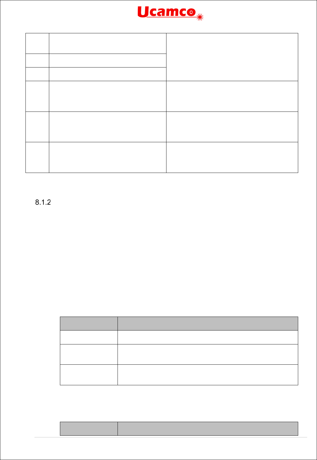
Copyright Ucamco NV 174
Having a question or remark about the spec? Please contact us at gerber@ucamco.com
MI Sets ‘Image mirroring’ graphics state
parameter
It is a waste of time to fully implement these
commands. The simplest is simply to ignore these
commands. Theoretically safer is to skip them if
they confirm the default and throw an error on any
other use; chances are you will never see the
error.
OF
Sets ‘Image offset’ graphics state parameter
SF
Sets ‘Scale factor’ graphics state parameter
IN Sets the name of the file image. Has no
effect. It is comment.
This is just a comment. Use G04 for comments.
See 4.1. Ignore it.
Sometimes used. Deprecated in 2013.
LN Loads a name. Has no effect. It is a
comment.
This is just a comment. Use G04 for comments.
See 4.1. Ignore it.
Sometimes used. Deprecated in 2013.
G74 Sets single quadrant mode Rarely used, and then usually to confirm a
default, but without practical effect.
Sometimes used. Deprecated in 2020.
Deprecated Gerber Commands
Axis Select (AS)
The AS command is deprecated since revision I1 from December 2012.
The historic AS command sets the correspondence between the X, Y data axes and the A, B
output device axes. It does not affect the image in computer to computer data exchange. It only
has an effect how the image is positioned on an output device.
The order of execution is always MI, SF, OF, IR and AS, independent of their order of
appearance in the file.
The AS command can only be used once, at the beginning of the file.
8.1.2.1 AS Command
The syntax for the AS command is:
AS = '%' (AS' ('AXBY'|'AYBX')) '*%';
Syntax
Comments
AS
AS for Axis Select
AXBY Assign output device axis A to data axis X, output device axis B to
data axis Y. This is the default.
AYBX Assign output device axis A to data axis Y, output device axis B to
data axis X.
8.1.2.2 Examples
Syntax
Comments
Copyright Ucamco NV 175
Having a question or remark about the spec? Please contact us at gerber@ucamco.com
%ASAXBY*%
Assign output device axis A to data axis X and output device axis B
to data axis Y
%ASAYBX*%
Assign output device axis A to data axis Y and output device axis B
to data axis X
Image Name (IN)
The IP command is deprecated since revision I4 from October 2013.
The historic IN command gives a name to the image contained in the Gerber file. The name
must comply with the syntax rules for a string as described in section 3.4.3. This command can
only be used once, at the beginning of the file.
IN has no effect on the image. A reader can ignore this command.
The informal information provide by IN can also be put a G04 comment.
8.1.3.1 IN Command
The syntax for the IN command is:
IN = '%' ('IN' name) '*%';
Syntax
Comments
IN
IN for Image Name
<Name>
Image name
8.1.3.2 Examples
Syntax
Comments
%INPANEL_1*%
Image name is ‘PANEL_1’
Image Polarity (IP)
The IP command is deprecated since revision I4 from October 2013.
IP sets positive or negative polarity for the entire image. It can only be used once, at the
beginning of the file.
8.1.4.1 Positive Image Polarity
Under positive image polarity, the image is generated as specified elsewhere in this document.
(In other words, the image generation has been assuming positive image polarity.)
8.1.4.2 Negative Image Polarity
The purpose of negative image polarity is to create a negative image, clear areas in a dark
background. The entire image plane in the background is initially dark instead of clear. The
effect of dark and clear polarity is toggled. The entire image is simply reversed, dark becomes
white and vice versa.
In negative image polarity, the first graphical object encountered must have dark polarity.

Copyright Ucamco NV 176
Having a question or remark about the spec? Please contact us at gerber@ucamco.com
8.1.4.3 IP Command
The syntax for the IP command is:
IP = '%' ('IP' ('POS'|'NEG')) '*%';
Syntax
Comments
IP
IP for Image Polarity
POS
Image has positive polarity
NEG
Image has negative polarity
8.1.4.4 Examples
Syntax
Comments
%IPPOS*%
Image has positive polarity
%IPNEG*%
Image has negative polarity
Image Rotation (IR)
The IR command is deprecated since revision I1 from December 2012.
IR rotates the entire image counterclockwise in increments of 90° around the image origin (0, 0).
All image objects are rotated. The IR command affects the entire image. It must be used only
once, at the beginning of the file. The order of execution is always MI, SF, OF, IR and AS,
independent of their order of appearance in the file.
8.1.5.1 IR Command
The syntax for the IR command is:
IR = '%' ('IR' ('0'|'90'|'180'|'270')) '*%';
Syntax
Comments
IR
IR for Image Rotation
0
Image rotation is 0° counterclockwise (no rotation)
90
Image rotation is 90° counterclockwise
180
Image rotation is 180° counterclockwise
270
Image rotation is 270° counterclockwise
8.1.5.2 Examples
Syntax
Comments
%IR0*%
No rotation

Copyright Ucamco NV 177
Having a question or remark about the spec? Please contact us at gerber@ucamco.com
%IR90*%
Image rotation is 90° counterclockwise
%IR270*%
Image rotation is 270° counterclockwise
Load Name (LN)
The IP command is deprecated since revision I4 from October 2013.
This historic command has no effect on the image and can be ignored.
LN assigns a name to the subsequent part of the file. It was intended as a human-readable
comment. Use the normal G04 command for human-readable comment. The LN command can
be used multiple times in a file.
8.1.6.1 LN Command
The syntax for the LN command is:
LN = '%' ('LN' name) '*%';
Syntax
Comments
LN
LN for Load Name
<Name>
The name must comply with the syntax for a string, see
section
3.4.3.
8.1.6.2 Examples
Syntax
Comments
%LNVia_anti-pads*%
The name ‘Via_anti-pads’ is to the subsequent file section
Mirror Image (MI)
The MI command is deprecated since revision I1 from December 2012.
MI sets the mirroring for the coordinate data. All the coordinate data – and only coordinate data
- are mirrored according to the specified factor. Step and repeat distances are not
coordinate data – see 4.9 - and hence are not mirrored. Apertures are not mirrored.
This command affects the entire image. It can only be used once, at the beginning of the file.
The default is no mirroring. The order of execution is always MI, SF, OF, IR and AS,
independent of their order of appearance in the file.
Quite a number of implementations incorrectly also mirror apertures and/or
step and repeat distances. These incorrect implementations make the MI
too risky to use. We strongly recommend not to use MI on output as you do
know how the reader will interpret the file. If an image must be mirrored,
write out the mirrored coordinates and apertures.
8.1.7.1 MI Command
The syntax for the MI command is:
Copyright Ucamco NV 178
Having a question or remark about the spec? Please contact us at gerber@ucamco.com
MI = '%' (['A'('0'|'1')]['B'('0'|'1')]) '*%';
Syntax
Comments
MI
MI for Mirror image
A(0|1) Controls mirroring of the A-axis data:
A0 – disables mirroring
A1 – enables mirroring (the image will be flipped over the B-axis)
If the A part is missing, then mirroring is disabled for the A-axis data
B(0|1) Controls mirroring of the B-axis data:
B0 – disables mirroring
B1 – enables mirroring (the image will be flipped over the A-axis)
If the B part is missing, then mirroring is disabled for the B-axis data
8.1.7.2 Examples
Syntax
Comments
%MIA0B0*%
No mirroring of A- or B-axis data
%MIA0B1*%
No mirroring of A-axis data
Mirror B-axis data
%MIB1*%
No mirroring of A-axis data
Mirror B-axis data
Offset (OF)
The OF command is deprecated since revision I1 from December 2012.
OF moves the final image up to plus or minus 99999.99999 units from the imaging device (0, 0)
point. The image can be moved along the imaging device A or B axis, or both. The offset values
used by OF command are absolute. If the A or B part is missing, the corresponding offset is 0.
The offset values are expressed in units specified by MO command. This command affects the
entire image. It can only be used once, at the beginning of the file. The order of execution is
always MI, SF, OF, IR and AS, independent of their order of appearance in the file.
8.1.8.1 OF Command
The syntax for the OF command is:
OF = '%' (['A' decimal]['B' decimal]) '*%';
Syntax
Comments
OF
OF for Offset
A<Offset>
Defines the offset along the output device A axis

Copyright Ucamco NV 179
Having a question or remark about the spec? Please contact us at gerber@ucamco.com
B<Offset>
Defines the offset along the output device B axis
The <Offset> value is a decimal number n preceded by the optional sign (‘+’ or ‘-’) with the
following limitation:
0
≤ n ≤ 99999.99999
The decimal part of n consists of not more than 5 digits.
8.1.8.2 Examples
Syntax
Comments
%OFA0B0*%
No offset
%OFA1.0B-1.5*%
Defines the offset: 1 unit along the A axis, -1.5 units along the B axis
%OFB5.0*%
Defines the offset: 0 units (i.e. no offset) along the A axis, 5 units along
the B axis
Scale Factor (SF)
The SF command is deprecated since revision I1 from December 2012.
SF sets a scale factor for the A- and/or B-axis coordinate data. All the coordinate data – and
only coordinate data - are multiplied by the specified factor for the corresponding axis. Step and
repeat distances – see 4.9 - are not coordinate data and hence are not scaled. Apertures
are not scaled.
This command affects the entire image. It can only be used once, at the beginning of the file.
The default scale factor is ‘1’. The factor values must be between 0.0001 and 999.99999. The
scale factor can be different for A and B axes. The order of execution is always MI, SF, OF, IR
and AS, independent of their order of appearance in the file.
Quite some legacy readers incorrectly also scale step and repeat distances.
These incorrect implementations make the SF too risky to use. Current
readers simply do not support the We strongly recommend not to use SF on
output as you do know how the reader will interpret the file. If an image must
be scaled, write out the scaled coordinates.
8.1.9.1 SF Command
The syntax for the SF command is:
SF = '%' ('SF' ['A' decimal]['B' decimal]) '*%';
Syntax
Comments
SF
SF for Scale Factor
A decimal
The scale factor for the A-axis data.
B defimal
The scale factor for the B-axis data.

Copyright Ucamco NV 180
Having a question or remark about the spec? Please contact us at gerber@ucamco.com
The scale factor is an unsigned decimal number n where 0.0001 ≤ n ≤ 999.99999.
8.1.9.2 Examples
Syntax
Comments
%SFA1B1*%
Scale factor 1. A decimal.
%SFA.5B3*%
Defines the scale factor: 0.5 for the A-axis, 3 for B. Decimals.

Copyright Ucamco NV 181
Having a question or remark about the spec? Please contact us at gerber@ucamco.com
Single-quadrant arc mode (G74)
Historically, there were two arc quadrant modes:
Single quadrant mode, set by G74 command
Multi quadrant mode, set by G75 command
The single-quadrant mode G74 was deprecated in 2021. Already in 2020 it occurred in <1/1000
files. In the vast majority its presence had no effect: a G75 set multi-quadrant mode before any
arc was effectively constructed. Implementors of Gerber input software that wish to support
legacy files will get a very long way without fully implementing G74 mode but give an error when
an attempt is made to create an arc in G74 – this error will exceedingly rarely occur.
Quadrant mode
Comments
Single quadrant (G74)
Deprecated
In single quadrant mode the arc is not allowed to extend over
more than 90°. The following relation must hold:
0° ≤ A ≤90°, where A is the arc angle
If the start point of the arc is equal to the end point, the arc has
length zero, i.e. it covers 0°. A separate operation is required for
each quadrant. A minimum of four operations is required for a full
circle.
Multi quadrant (G75)
Current
In multi quadrant mode the arc is allowed to extend over more
than 90°. To avoid ambiguity between 0° and 360° arcs the
following relation must hold:
0° < A ≤ 360°, where A is the arc angle
If the start point of the arc is equal to the end point, the arc is a full
circle of 360°.
Quadrant modes
The syntax of the G74 commands is:
G74 = :('G74') '*';
Example:
G74*
The syntax of the D01 command in single quadrant circular interpolation mode is:
D01 = (['X' x_coordinate] ['Y' y_coordinate] 'D01' 'I' x_distance 'J' Y_distance ) '*';
Syntax
Comments
X x_coordinate X_coordinate defines the X coordinate of the end point of the arc.
arc. It is of the coordinate data type. The default is the X coordinate
of the current point.
Y y_coordinate
As above, but for the Y axis.
I x_distance The x_distance defines the distance between the arc start point and
the center parallel to the X axis. Distance is ≥ 0. It is of the
coordinate data type.
J<Distance>>
As above, but for the Y axis.

Copyright Ucamco NV 182
Having a question or remark about the spec? Please contact us at gerber@ucamco.com
Syntax
Comments
D01
Interpolate operation code
49. Circular interpolation example
In single quadrant mode, awkwardly, the sign of the offsets is omitted, converting them to
unsigned distances. There are four candidates for the center: (<Current X> +/- <X distance>,
<Current Y> +/- <Y distance>). The center is the candidate that results in an arc with the
specified orientation, not greater than 90° and with the least deviation. The reason for this oddity
is purely historic, from a very distant past.
Example:
Syntax
Comments
G74*
D10*
X1100Y600D02*
G03*
X700Y1000I400J0D01*
X300Y600I0J400D01*
X700Y200I400J0D01*
X1100Y600I0J400D01*
X300D02*
G01*
X1100D01*
X700Y200D02*
Y1000D01*
Set single quadrant mode
Select aperture 10 as current aperture
Set the current point to (11, 6)
Set counterclockwise interpolation mode
Create quarter arc object (radius 4) to (7, 10)
Create quarter arc object (radius 4) to (3, 6)
Create quarter arc object (radius 4) to (7, 2)
Create quarter arc object (radius 4) to (11, 6)
Set the current point to (3 ,6)
Set linear interpolation mode
Create draw object to (11, 6)
Set the current point to (7, 2)
Create draw object to (7, 10)


Copyright Ucamco NV 184
Having a question or remark about the spec? Please contact us at gerber@ucamco.com
In important difference between G74 and G75 arcs is what happens when start point and end
point coincide. For G75 this represents a full 360° arc, in G75 a zero-degree arc. Some
examples.
Syntax
Comments
D10*
G01*
X0Y600D02*
G74*
G02*
X0Y600I500J0D01*
Select aperture 10 as current aperture
Set linear interpolation mode
Set the current point to (0, 6)
Set single quadrant mode
Set clockwise circular interpolation mode
Create arc object to (0, 6) with radius 5
The resulting image is small dot, an instance of the aperture, at position (0, 6)
Syntax
Comments
D10*
G01*
X0Y600D02*
G75*
G02*
X0Y600I500J0D01*
Select aperture 10 as current aperture
Set linear interpolation mode
Set the current point to (0, 6)
Multi quadrant mode
Set clockwise circular interpolation mode
Create arc object to (0, 6) with center (5,6)
The resulting image is a full circle.

Copyright Ucamco NV 185
Having a question or remark about the spec? Please contact us at gerber@ucamco.com
8.2 Deprecated Command Options
Format Specification (FS) Options
This section describes deprecated options of the FS command (see 4.1).
The FS command could also be used to specify the following format characteristics:
Trailing zero omission
Incremental coordinate notation
Low resolution (less than 6 decimals in inch units and less than 5 in mm units).
8.2.1.1 Trailing Zero Omission
Trailing zero omission is deprecated since revision 2015.06.
Trailing zero omission some or all trailing zero’s can be omitted but all leading zero’s are
required. To interpret the coordinate string, it is first padded with zero’s at the back until its
length fits the coordinate format. For example, with the “23” coordinate format, “15” is padded to
“15000” and therefore represents 15.000.
The coordinate data must contain at least one digit. Zero therefore should be encoded as “0”.
Trailing zero omission is specified by ‘T’ after the FS code. (The normal leading zero omission is
specified by ‘L’ after the FS code.)
Example:
%FSTAX25Y25*%
Trailing zero omission is rarely found in legacy files. Gerber readers will go a long way without
supporting it.
8.2.1.2 Incremental Notation
Incremental notation is deprecated since revision I1 from December 2012.
Incremental notation means that coordinate values are as the incremental distances from the
previous coordinate position. It is specified by the "I" in the FS command, after the "L" or "T" for
leading or trailing. (The normal absolute notation is specified by ‘A’ in the FS command.)
Example:
%FSLIX25Y25*%
%FSTIX36Y36*%
Incremental notation was sometimes used as a simplistic compression when saving a few bytes
was a fantastic advantage, and before the invention of Lempel–Ziv–Welch (LZW) and other
lossless compression methods. The problem is that the accumulation of rounding errors leads to
significant loss or precision. This results in poor registration, invalid arcs, self-intersecting
contours, often resulting in scrap. Avoid incremental notation like the plague.
Incremental notation is fortunately but rarely used in legacy files. Gerber readers will go a long
way without supporting it.

Copyright Ucamco NV 186
Having a question or remark about the spec? Please contact us at gerber@ucamco.com
8.2.1.3 Low resolution
Low resolution, this is using less than 6 decimals in inch units and less than 5 decimals in mm
units is deprecated since revision 2015.06.
Low resolution was introduced in the 1960's as a simplistic compression method when saving a
few bytes was of paramount importance, and computers were too feeble for proper lossless
compression methods such as Lempel–Ziv–Welch (LZW).
Low resolution loses numerical precision and poor numerical precision is the main cause of
often obscure bugs in geometric software. It leads to poor registration of objects between PCB
layers; loss of accuracy; self-intersecting contours; invalid arcs; small arcs turning in full circles,
missing clearances. Low resolution is the main cause of problems with Gerber files, sometimes
leading to scrap.
Unfortunately, low resolution files are still quite common. There are even files in inch with 3
decimals, or a resolution of 1 mil; this is asking for problems.
It is sometimes recommended to use low resolution because some Gerber readers allegedly
only handle low resolutions. Do not listen. This may have been true in a distant past, but it no
longer true, if it ever was. Ask yourself: does it make sense to risk scrap to save a few bytes or
to cater for a few rumored stone-age implementations? The days that saving a few bytes was
important are long gone. The risks of low resolution remain. Avoid low resolution like the plague.
Low resolution files are unfortunately quite common in legacy files. Gerber readers that do not
support low resolution will fail to read a significant fraction of Gerber files.
Rectangular Hole in Standard Apertures
Rectangular holes in standard apertures are deprecated since revision 2015.06. They occur
very rarely in legacy files.
In addition to the round hole described in section 4.4 older versions of this
specification also allowed rectangular holes. Rectangular holes do not rotate
with the aperture, according to these historic specifications. This is very
counterintuitive and a source of errors. Rectangular holes were deprecated
because of this problem, and because rectangular holes are not very useful
in the first place. Do not use them. If you need a rectangular hole construct a macro aperture.
The syntax of a rectangular hole was common to all standard apertures:
hole = x_hole_size Y y_hole_size
The parameters specify the X and Y sizes of the hole. Decimals >
0.
The hole must strictly fit within the standard aperture. It is centered on the aperture.
Example:
%FSLAX26Y26*%
%MOMM*%
%ADD10C,10X5X5*%
%ADD11C,1*%
G01*
%LPD*%
D11*
X-25000000Y-1000000D02*
X25000000Y1000000D01*
D10*
X0Y0D03*

Copyright Ucamco NV 187
Having a question or remark about the spec? Please contact us at gerber@ucamco.com
M02*
52. Standard (circle) aperture with a rectangular hole above a draw
Note that the draw is visible through the hole.
Rectangular holes appear very rarely in legacy files.
Draws and Arcs with Rectangular Apertures
The effect of stroking a line segment with a rectangular aperture is illustrated below. If the
rectangle aperture is aligned with the line being stroked the result is a draw with line endings
which have right angles:
53. Creating a draw: the aperture is aligned with line
If the rectangle is not aligned the result is as in the illustration below. The rectangle is not
automatically rotated to align with the line being stroked.
54. Creating a draw: the aperture is not aligned with line
Line being stroked Aperture Draw
Line being stroked
Aperture Draw

Copyright Ucamco NV 188
Having a question or remark about the spec? Please contact us at gerber@ucamco.com
This was only allowed with the solid rectangle standard aperture. Other standard apertures or
macro apertures that fortuitously have a rectangular shape are not allowed.
This option was deprecated in 2020.09. Drawing with rectangular was never used often, even
less at other angles than multiples of 90º. A developer of Gerber input will get a long way if he
only implements a warning on interpolations with rectangular apertures.
Macro Primitive Code 2, Vector Line
Primitive 2 was deprecated in 2015. It occurs but very rarely in legacy files.
Primitive 2 is identical to primitive 20. See 4.5.1.4.
Macro Primitive Code 22, Lower Left Line
Primitive 22 was deprecated in 2015. It occurs but very rarely in legacy files.
A lower left line primitive is a rectangle defined by its width, height, and the lower left point.
Modifier number
Description
1
Exposure off/on (0/1))
2
Rectangle width
, a decimal ≥ 0
.
3
Rectangle height
, a decimal ≥ 0.
4
A decimal defining the
X coordinate of lower left point.
5
A decimal defining the
Y coordinate of lower left point.
6
A decimal defining the r
otation angle around the origin (rotation is not
around the center of the object)
1. Line (lower left) primitive
Example:
%AMLINE2*22,1,6.8,1.2,0,0,0*%
2
4, 5 3

Copyright Ucamco NV 189
Having a question or remark about the spec? Please contact us at gerber@ucamco.com
Macro Primitive Code 6, Moiré
This primitive was deprecated in 2021. It is very rarely, if ever, used in legacy files.
The moiré primitive is a cross hair centered on concentric rings. Exposure is always on.
Parameter
number
Description
1
Center point X coordinate.
2
Center point Y coordinate.
3
Outer diameter of outer concentric ring ≥ 0.
4
Ring thickness ≥ 0.
5
Gap between rings ≥ 0.
6 Maximum number of rings. An integer ≥ 0. The effective number of
rings can be less if the center is reached. If there is not enough space
for the inner ring it becomes a full disc.
7
Crosshair thickness ≥ 0. If the thickness is 0 there are no crosshairs.
8
Crosshair length ≥ 0. If the length is 0 there are no crosshairs.
9 Rotation angle, in degrees counterclockwise. The primitive is rotated
around the origin of the macro definition, i.e. the (0, 0) point of macro
coordinates.
2. Moiré primitive
5
1, 2
8
3
7
4

Copyright Ucamco NV 190
Having a question or remark about the spec? Please contact us at gerber@ucamco.com
Below there is an example of an AM command that uses the moiré primitive.
Example:
%AMMOIRE*
6,0,0,5,0.5,0.5,2,0.1,6,0*%
8.3 Deprecated Syntax Variations
Combining G01/G02/G03 and D01 in a single command.
This construction is deprecated since revision 2015.06.
The command codes G01, G02, G03 could be put at the beginning of the word containing a D01
command. The graphics state is then modified before the D01 is executed.
Example:
G01X100Y100D01*
G01 sets the interpolation mode to linear and this used to process the coordinate data
X100Y100 from the same word as well as the coordinate data X200Y200 from the next word.
The syntax was as follows:
GnnD01 = ('G' ('01'|'02'|'03') coordinate_data 'D01') '*'
This construction is a useless variation and is deprecated since revision 2015.06. However, it
happens quite frequently in legacy files, so readers may want to support it.

Copyright Ucamco NV 191
Having a question or remark about the spec? Please contact us at gerber@ucamco.com
Coordinate Data without Operation Code
Coordinate data without explicit operation code after a D01, on other words the modal use of
D01, is deprecated since revision I1 from December 2012.
A D01 code sets the deprecated operation mode to interpolate. It remains in interpolate mode
till any other D code is encountered. In sequences of D01 operations this allows omitting an
explicit D01 code after the first operation.
Example:
D10*
X700Y1000D01*
X1200Y1000*
X1200Y1300*
D11*
X1700Y2000D01*
X2200Y2000*
X2200Y2300*
The operation mode is only defined after a D01. The operation mode after a D02, D03 or an
aperture selection (Dnn with nn≥10) is undefined. Therefore a file containing coordinates without
operation code after a D02, D03 or an aperture selection (Dnn with nn≥10) is invalid.
Warning: Coordinate data without explicit operation code saves a few bytes but its exact
use is not intuitive in relation to D03. The risk of scrap far outweighs the meager benefit.
Style Variations in Command Codes
Sometimes a word command such as G01 was spelled as G1, or g01, or G001. These
variations were discouraged but tolerated. These variations were finally revoked in 2020.09 –
only G01 style is allowed.
Deprecated usage of SR
These constructions are deprecated since revision 2016.01.
The command %SRX1Y1I0J0*% strictly speaking starts a step and repeat of 1x1, i.e. no step
and repeat at all. It is historically sometimes used as an alternative for an %SR*% to close an
SR statement. This is still used quite frequently.
Sometimes an SR command other than 1x1 such as %SRX2Y3I1,5J2.2*% is put seemingly
inside an SR statement. Its effect is then to terminate the current SR statement and start a new
one with its parameters. This is used rarely.
Another deprecated variation is that an SR statement at the end of a file is not closed. The end
of file M02* is then an implicit close. This is used rarely.
Another variation is that the file header contains a %SRX1Y1I0J0*%. This does not mean a
futile 1x1 step and repeat is started. It just indicates that the file does not start with a step and
repeat, which is obvious. This command can be ignored. This is used quite frequently.
8.4 Deprecated Attribute Values
The following values for the .AperFuntion attribute were deprecated in 2019.06. They were very
rarely, if ever, used.

Copyright Ucamco NV 192
Having a question or remark about the spec? Please contact us at gerber@ucamco.com
CutOut
PCB cut-outs. This is the generic term for a hole other
than a drill hole.
Slot
PCB slots. This is a subset of the cut-outs. Which cut-
outs are called slots is subjective. In case of doubt use
the value CutOut.
Cavity
Cavities in a PCB.

Copyright Ucamco NV 193
Having a question or remark about the spec? Please contact us at gerber@ucamco.com
8.5 Standard Gerber (RS-274-D)
The current Gerber layer format is also known as RS-274X or Extended Gerber. There was also
a historic format called Standard Gerber or RS-274-D format.
Standard Gerber is technically obsolete. It and was revoked in revision I1 from December 2012
and superseded by RS-274X.
Standard Gerber is revoked and superseded by Extended Gerber, which is the current Gerber
format. Consequently, Standard Gerber no longer complies with the Gerber specification. Files
in that format can no longer be correctly called Gerber files. Standard Gerber files are not only
deprecated, they are simply invalid.
It differs from the current Gerber format (RS-274X), in that it:
• did not support G36 and G37 codes
• did not support any extended commands
• did not support attributes
Standard Gerber did not allow defining the coordinate format or aperture shapes. It was
incomplete as an image description format. It lacked the imaging primitives needed to
unequivocally transfer information from PCB CAD to CAM.
The word “standard” is misleading here. Standard Gerber was standard NC format. It was not a
standard image format: image generation needs a so-called wheel file, and that wheel file was
not governed by a standard. The interpretation of a wheel files, and consequently of a Standard
Gerber files, was subjective. In Extended Gerber (RS-274X) image generation is fully governed
by the standard. Extended Gerber is the true image standard.
Standard Gerber had major drawbacks compared to the current Gerber format and did not offer
a single advantage. Standard Gerber is obsolete. There is not a single valid reason to use
standard Gerber rather than Extended Gerber.
Always use Extended Gerber (RS-274X). Never use Standard Gerber.
Warning: The responsibility of errors or misunderstandings about the wheel file when
processing a Standard Gerber file rests solely with the party that decided to use revoked
Standard Gerber, with its informal and non-standardized wheel file, rather than Extended
Gerber, which is unequivocally and formally standardized.

Copyright Ucamco NV 194
Having a question or remark about the spec? Please contact us at gerber@ucamco.com
9 References
American National Standard for Information Systems — Coded Character Sets — 7-Bit
American National Standard Code for Information Interchange (7-Bit ASCII), ANSI X3.4-1986
https://en.wikipedia.org/wiki/MD5
https://en.wikipedia.org/wiki/Unicode
https://en.wikipedia.org/wiki/UTF-8
http://en.wikipedia.org/wiki/ISO_8601
https://en.wikipedia.org/wiki/Binary_image
https://en.wikipedia.org/wiki/Zip_(file_format)
https://tools.ietf.org/html/rfc4122
https://msdn.microsoft.com/en-us/library/windows/desktop/aa378623(v=vs.85).aspx
https://developer.apple.com/library/mac/documentation/Foundation/Reference/NSUUID_Class
The Inventor's Dilemma: The Remarkable Life of H. Joseph Gerber, by David Gerber.
https://tatsu.readthedocs.io/en/stable/
. Documentation for the TatSu PEG parser generator.
https://en.wikipedia.org/wiki/Parsing_expression_grammar
https://bford.info/packrat/ Bryan Fords page on parsing expression grammars.

Copyright Ucamco NV 195
Having a question or remark about the spec? Please contact us at gerber@ucamco.com
10 History
The Gerber format derives its name from the former Gerber Systems Corp. A leading supplier of
vector photoplotters from the 1960s onwards, Gerber based its plotter input on a subset of the
EIA RS-274-D NC format, and in1980, it published a well-written specification titled “Gerber
Format: a subset of EIA RS-274-D; plot data format reference book”. The format was so well
suited for its task that it was widely adopted and became the de-facto standard format for vector
plotters, known as Standard Gerber.
Vector photoplotters are NC machines, and Standard Gerber, which is dedicated to vector
photoplotters, is an NC format. As of the 1980s, vector photoplotters started losing ground to
raster plotters. Based on bitmap technology, these newer devices demanded rather more than a
simple NC format, so Gerber extended the original NC format with so called “Mass Parameters”,
converting it to a fully-fledged image file formats. This resulted in a family of effective image
description formats designed specifically to drive Gerber's PCB devices and raster plotters. In
1998 Gerber Systems Corp. was taken over by Barco and incorporated into its PCB division –
Barco ETS, now Ucamco. At this point, Barco drew all the variants in Gerber's family of formats
into a single standard image format.
On September 21, 1998 Barco-Gerber published the Gerber RS-274X Format User's Guide.
The format became known as Extended Gerber or GerberX. This is a full image description
format, which means that an Extended Gerber file contains the complete description of a PCB
layer, providing everything needed for an operator to generate a PCB image, and enabling any
aperture shape to be defined. Unlike Standard Gerber, it does not need the support of additional
external files, and it specifies planes and pads clearly and simply without the need for painting
or vector-fill. The Extended Gerber format quickly superseded Standard Gerber as the de facto
standard for PCB image data, and is sometimes called "the backbone of the electronics
industry". A sequence of revisions clarifying the specification was published over the years,
culminating in revision H of January 2012.
During 2012, Ucamco reviewed the entire format in depth in “the great reform”. Over 10.000
files from all over the world were gathered into a representative library to help establish current
practice. Rarely used and historic format elements were deprecated. Format elements with
conflicting interpretations in the market were either deprecated or clarified. The specification
document itself was re-organized, the quality of the text and the drawings improved and many
new drawings were added. This resulted in The Gerber Format Specification, revision I1
published in December 2012. Revisions I2, I3 and finally I4 from November 2013 further
improved the document. The result was a powerfully clear and simple format, without needless
embellishments, focused on the current needs of the PCB industry. This version of the Gerber
Format was developed by Karel Tavernier and Rik Breemeersch. They were assisted by an
advisory group including Ludek Brukner, Artem Kostyukovich, Jiri Martinek, Adam Newington,
Denis Morin, Karel Langhout and Dirk Leroy. Grateful thanks are extended to all those who
helped the development of the revision by posting their questions, remarks and suggestions on
the Ucamco website. Particular thanks are due to Paul Wells-Edwards whose insightful
comments contributed substantially to the revision.
Until this point, Gerber was purely an image description format. Recognizing that a PCB image
must be supported with meta-information that describes, say, the function of an image file in the
layer structure, Ucamco realized that it could convey that information clearly and unequivocally
using attributes. Accordingly, and in June 2013, the company publicly proposed to extend the
Gerber format using attributes, and invited feedback on its proposal from the Gerber user
community. The outcome of this was revision J1, completed in February 2014, during which
Gerber got its attributes. It was a major step forward for the format, at least on a par with the
changes made when Standard Gerber became Extended Gerber. Sometimes called the second
extension, the latest version of the Gerber format is known as Gerber version 2, or X2 (as

Copyright Ucamco NV 196
Having a question or remark about the spec? Please contact us at gerber@ucamco.com
opposed to X1, which is Gerber without attributes). Gerber version 2 is fully backward
compatible as attributes do not affect the image at all. Subsequent revisions, J2 to J4, clarified
the specification and added new standard attributes. Gerber version 2 was developed by Karel
Tavernier, Ludek Brukner and Thomas Weyn. They were assisted by an advisory group
including Roland Polliger, Luc Samyn, Wim De Greve, Dirk Leroy and Rik Breemeersch.
In September 2014 Ucamco published an open letter declaring Standard Gerber obsolete and
revoking it.
In August 2015, Ucamco published a draft specification adding nested step and repeat and
block apertures to make panel descriptions more efficient, calling for comments from the user
community. In November 2016 the review process was closed after substantial input and
modifications and the final version included in revision 2016.12. This revision was developed by
Karel Tavernier and Rik Breemeersch.
Early in 2015, the entire specification was reviewed once again by Karel Tavernier, Thomas
Weyn and Artem Kostyukovich focused on making the specification easier to read and
understand, while taking great care to ensure consistent and precise terminology. Some further
elements were identified as superfluous and were deprecated. Not least, special attention was
given to the 'Overview' chapter, with the aim of turning it into a tutorial that can be understood
by non-experts. The result of this work is revision 2015.06.
In July 2016 Karel Tavernier from Ucamco published a draft specification to include netlist
information in Gerber for public review. Several revisions of the draft were triggered by input
from users. The final version was in included in revision 2016.11 from November 2, 2016.
In March 2017 Karel Tavernier from Ucamco published a draft specification to include fab
documentation in Gerber for public review.
In May 2020 Karel Tavernier from Ucamco published a specification for including component
information in Gerber, aka X3.

Copyright Ucamco NV 197
Having a question or remark about the spec? Please contact us at gerber@ucamco.com
11 Revisions
11.1 Revision 2021.02
Deprecated single quadrant mode (G74) and macro primitive code 6 (moiré).
Now includes a formal grammar for the complete format. See 3.5.
Several typo's were fixed; thanks to Nick Meeker and Kevin Shi for their careful review. The
term 'data block' was replaced by 'word' to eliminate confusion with aperture blocks.
11.2 Revision 2020.09 – X3
In March 2020 a specification for including component information – Gerber X3 2020.03 – was
published. Gerber X3 was developed in discussion with a team of people. Karel Tavernier
developed a prototype specification which was circulated privately with Wim De Greve, Jean-
Pierre Charras, Thiadmer Riemersma, Bruce McKibben and Rafal Powierski in December 2018.
In intense discussion among this group the draft went through five revisions until a first public
draft was published in October 2019, calling for input from the user community. The review
process was closed in February 2020 with the publication of the separate X3 specification, now
merged in this document.
This separate specification on components is now merged into this main specification.
Gerber now accepts Unicode characters for attribute values that contain user-defined meta-
information, and therefore may require special characters and other languages than English.
Draws with rectangular apertures were deprecated, see 8.2.3, as were some style variations in
word commands, see 8.3.3.
Clarified the semantics of the .GenerationSoftware attribute. Specified more clearly how drill
files must be constructed, as suggested by Wim De Greve and Luc Samyn.
Fixed errors and oversights pointed out by Greg Huangqi and Jim J. Jewett. Especially Jim J.
Jewett reviewed the specification in great detail. Replaced the unusual term 'modifier' with the
more usual term 'parameter'.
Revision 2020.09 was developed by Karel Tavernier.
11.3 Revision 2019.09
Replaced the option [Filled|NotFilled] on the ViaDrill value of the .AperFunction attribute with the
more specific IPC-4761 types, see 5.6.10.
Revision 2019.09 was developed by Karel Tavernier.
11.4 Revision 2019.06
The .AperFunction values CutOut, Slot and Cavity were deprecated. See 8.3.
Made it more explicit that macro aperture names cannot be reused, see Error! Reference
source not found.. Corrected an error in the examples pointed out by Abe Tusk, and in 2.1,
pointed out by Radim Halíř.
Revision 2019.06 was developed by Karel Tavernier.

Copyright Ucamco NV 198
Having a question or remark about the spec? Please contact us at gerber@ucamco.com
11.5 Revision 2018.11
Removed the .PF attribute, and replaced its content by an additional optional field to the .P
attribute. See 5.6.14.
Fixed a number of typos and minor errors pointed out by Jörg Naujoks, Rik Breemeersh and
Radim Halíř.
Revision 2018.11 was developed by Karel Tavernier.
11.6 Revision 2018.09
Corrected an error in the polygon aperture, section 4.4.5, and polygon primitive, section 4.5.1.7.
Clarified the rotation of the deprecated rectangular holes in apertures, section 8.2.2 These
issues were pointed out by Remco Poelstra.
Corrected an error in the moiré primitive specification, section 8.2.6. The error was pointed out
by Vasily Turchenko.
Clarified how object attributes are attached to regions, triggered by remarks from Radim Halíř.
Defined allowed range of the scale factor in 4.9.5, as suggested by Andreas Weidinger.
Defined orientation of text mirroring in section 5.6.12. Triggered by Nicholas Meeker.
Nicholas Meeker, Andreas Weidinger, Radim Halíř and Denis Morin carefully proofread the
document, which resulted in many text corrections.
Revision 2018.09 was developed by Karel Tavernier.
11.7 Revision 2018.06
Removed PressFit option from the ComponentPad attribute value; it is also a ComponentDrill
option and that is sufficient.
Clarified pad attribute values for via, component, SMD, BGA on inner layers. Clarified FS
command, see 4.1 and 8.2.1. Fixed broken links to references indicated by Vasily Turchenko.
Revision 2018.06 was developed by Karel Tavernier.
11.8 Revision 2018.05
Added .PF attribute, as suggested by Matthew Sanders.
Corrected errors in an example in 4.9.1 pointed out by Erik Forwerk. Corrected errors in the SR
definition and Backus-Naur form pointed out by Remco Poelstra, see 4.11. Simplified the
Backus-Naur form of the region statement, see 4.10.2. Corrected an error in 5.4 pointed out by
Dries Soentjens.
Revision 2018.05 was developed by Karel Tavernier.
11.9 Revision 2017.11
Allow the .N attribute not only on copper layers but also on plated drill layers, see 5.6.13.
Remove .FileFunction value Keep-out. Use Profile instead.
Specified that to combine files zip is the only allowed archive format, as suggested by Rafal
Powierski.

Copyright Ucamco NV 199
Having a question or remark about the spec? Please contact us at gerber@ucamco.com
Simplified the Backus-Naur form of aperture blocks, see 4.11.2. Added synoptic table with
macro primitives in 4.5.1.1. Added synoptic table one with standard apertures in 4.4.1. Added
Backus-Naur form of the region statement. Added link to the Reference Gerber Viewer in 1.3.
Fixed typos pointed out by Forest Darling. Fixed a number or typos pointed out by Radim Halíř.
Revision 2017.11 was developed by Karel Tavernier.
11.10 Revision 2017.05
Added the new file attribute .SameCoordinates, see 5.6.5.
Added file functions Depthrout, Viafill, Vcut, and Vcutmap.
Created section 5.6.15.1 with guidelines on the use of attributes in fabrication data; added
guidelines on how to define the PCB profile in 6.2.
Reorganized and edited the chapter Overview. Clarified section on zero-size apertures.
Corrected an error in the comment in example 6.6.1.2 pointed out by Nav Mohammed.
Corrected errors in the examples in 5.6.5 pointed out by Rik Breemeersch,
Revision 2017.05 was developed by Karel Tavernier.
11.11 Revision 2017.03
Added section 5.6.15.1, specifying how to put text in the image.
Changed file function Gluemask to Glue; added explanation; see 5.6.3.
Reorganized chapter 3.5. Extended section 4.10.5.
Corrections in 4.9.1, 4.9.5, 4.10.1 and in Aperture Attributes on Regions triggered by remarks
from Remco Poelstra. Corrected an error in example 0 pointed out by Danilo Bargen.
Revision 2017.03 was developed by Karel Tavernier.
11.12 Revision 2016.12 – Nested step and repeat
This is a major revision with powerful new imaging functions: 4.11, 0, 4.9.4 and 4.9.5. These
allow nested step and repeat to define panels efficiently, see 4.11.3 and 4.11.4.
Thera are fixes for errors in examples, pointed out by Danilo Bargen and Urban Bruhin.
Revision 2016.12, and especially the new imaging function for panels was developed by Karel
Tavernier and Rik Breemeersch. The first draft of these functions was published in August 2016.
During the public review process. Thomas Weyn, Bruce McKibben, Masao Miyashita and
Remco Poelstra provided essential input.
11.13 Revision 2016.11
This major revision allows to include the CAD netlist to Gerber files by adding three new
standard object attributes – see 5.6.15.1 above. The goal of the Gerber CAD netlist is to
facilitate upfront communication between the different parties involved in design, assembly and
automation. The X2 attributes proposed include CAD netlists in Gerber fabrication data and
allow to:
• Attach the component reference designator, pin number and net name to the component
pads in the outer copper layers. This information is essential for a complete board
display and for a complete board display. More importantly, the netlist provides a
powerful checksum to guarantee PCB fabrication data integrity.

Copyright Ucamco NV 200
Having a question or remark about the spec? Please contact us at gerber@ucamco.com
• Attach the netlist name to any conducting object on any copper layer. Lightweight
viewers can then display netlists without the need for an algorithm to compute
connectivity
• Attach the component reference to any object, e.g. to identify all the legend objects
belonging to a given component, for example.
Several text improvements. Section 4.10.3 on regions clarified triggered by deep questions
asked by Remco Poelstra.
Revision 2016.11 was developed by Karel Tavernier. Jean-Pierre Charras provided essential
input on the CAD netlist, and further remarks by Remco Poelstra and Wim De Greve were
included.
11.14 Revision 2016.09
New or modified attribute values – see 5.6.10:
• Replaced file function Drawing with OtherDrawing.
• Added the optional field Filled|NotFilled to ViaDrill.
• Added aperture function EtchedComponent.
Added object attributes – see 5.4. Object attributes attach information to individual graphical
objects.
Corrected an error in example 4.10.4.6. The error was pointed out by Thomas van Soest and
Siegfried Hildebrand. Clarified the syntax of attaching aperture attributes to regions. Added Perl
script to show precisely how to calculate the .MD5. Several other clarifications.
Revision 2016.09 was developed by Karel Tavernier.
11.15 Revision 2016.06
Added a section on back-drilling job triggered by questions from Alexey Sabunin. See 6.6.1.1.
The .ProjectID UUID was changed to RFC4122; rewritten by Remco Poelstra. See 5.6.8.
Aperture function attributes were clarified triggered by remarks from John Cheesman. Drill sizes
were clarified triggered by remarks from Jeff Loyer.
11.16 Revision 2016.04
Added PressFit label to component drill and pad attributes; see ComponentPad and
ComponentDrill. Revoked default on current point.
Text improvements that do not change the format: Removed superfluous concept of level and
replaced the name ‘Level Polarity’ by ‘Load Polarity. Various other text improvements.
11.17 Revision 2016.01
Added drill and pad functions for castellated holes. Added optional types break-out and tooling
on MechanicalDrill.
Deprecated closing an SR with the M02.
Text improvements that do not change the format: Clarified .AperFunction attribute values.
Clarified when to use of standard or user attributes. Clarified how aperture attributes can be set
on regions.

Copyright Ucamco NV 201
Having a question or remark about the spec? Please contact us at gerber@ucamco.com
11.18 Revision 2015.10
Added items to section Errors and Bad Practices.
Added file function attribute .FilePolarity.
Refined drawing .FileFunction attributes Replaced Mechanical by FabricationDrawing and
Assembly by AssemblyDrawing. Added definitions to the drawing types. Added mandatory
(Top|Bot) to .AssemblyDrawing, as suggested by Malcolm Lear. Added ArrayDrawing.
11.19 Revision 2015.07
The superfluous and rarely, if ever, used macro primitives 2 and 22 were revoked. The
.AperFunction aperture attribute was simplified:
• Filled / NotFilled option is removed for the ViaDrill function
• ImpC / NotC option is removed from the Conductor function
11.20 Revision 2015.06
New file attributes were specified: .GenerationSoftware (5.6.5), .CreationDate (5.6.5) and
.ProjectId (5.6.8).
The mistakenly omitted rotation parameter of the circle macro primitive was restored. Unicode
escape sequences in strings are now defined.
Operation syntax combining the G and D codes in a single word were deprecated. The
rectangular hole in standard apertures was deprecated. Usage of low resolutions and trailing
zero omission in the FS command was deprecated.
The entire document was revised for clarity. The readability of the text was improved. The
terminology was made consistent. The glossary was expanded. A number of additional images
were added, including the Gerber file processing diagrams, command types diagram, aperture
macro rotation illustration. Some of existing images were recreated to improve the quality.
Several new tables were added to explain the relation between D code commands and graphics
state parameters. The glossary was updated. The sections were rearranged.
From now the revision numbering follows the year.month scheme as in 2015.06.
11.21 Revision J3 (2014 10)
The .FileFunction values for copper and drill layers were extended to contain more information
about the complete job.
11.22 Revision J4 (2015 02)
The .AperFunction values “Slot”, “CutOut” and “Cavity” were added. The text on standard
attributes was made more explicit. An example of a poorly constructed plane was added.
11.23 Revision J2 (2014 07)
Attaching aperture attributes with regions was much simplified. A section about numerical
accuracy was added.

Copyright Ucamco NV 202
Having a question or remark about the spec? Please contact us at gerber@ucamco.com
11.24 Revision J1 (2014 02) – X2
This revision created Gerber X2 by adding attributes to what was hitherto a pure image format.
See chapter 5. X2 is Gerber version 2, with “X1” being Gerber version 1, without attributes.
Gerber X2 is backward compatible as attributes do not affect image generation.
11.25 Revision I4 (2013 10)
The commands LN, IN and IP were deprecated. The possibility of re-assigning D codes was
revoked.
The regions overview section 4.10.1 was expanded and examples were added different places
in 4.10 to further clarify regions. The chapters on command codes and syntax were
restructured. The constraints on the thermal primitive parameters were made more explicit.
Wording was improved in several places. The term ‘(mass) parameter’ was replaced by
‘extended command’.
11.26 Revision I3 (2013 06)
Questions about the order and precise effect of the deprecated commands MI, SF, OF, IR and
AS were clarified. Coincident contour segments were explicitly defined.
11.27 Revision I2 (2013 04)
The “exposure on/off” parameter in macro apertures and the holes in standard apertures are
sometimes incorrectly implemented. These features were explained in more detail. Readers and
writers of Gerber files are urged to review their implementation in this light.
11.28 Revision I1 (2012 12)
General. The entire specification was extensively reviewed for clarity. The document was re-
organized, the text and the drawings have been improved and many new drawings were added.
Deprecated elements. Elements of the format that are rarely used and superfluous or prone to
misunderstanding have been deprecated. They are grouped together in the second part of this
document. The first part contains the current format, which is clean and focused. We urge all
creators of Gerber files no longer to use deprecated elements of the format.
Graphics state and operation codes. The underlying concept of the graphics state and
operation codes is now explicitly described. See section 2.5 and 2.5. We urge all providers of
Gerber software to review their implementation in the light of these sections.
Defaults. In previous revisions the definitions of the default values for the modes were scattered
throughout the text or were sometimes omitted. All default values are now unequivocally
specified in an easy-to-read table. See 2.5. We urge all providers of Gerber software to review
their handling of defaults.
Rotation of macro primitives. The rotation center of macro primitives was clarified. See 4.5.3.
We urge providers of Gerber software to review their handling of the rotation of macro
primitives.
G36/G37. The whole section is now much more specific. We urge providers of Gerber software
to review their contour generation in this light.

Copyright Ucamco NV 203
Having a question or remark about the spec? Please contact us at gerber@ucamco.com
Coordinate data. Coordinate data without D01/D02/D03 in the same word can lead to
confusion. It therefore has been deprecated. See 8.1.10. We urge all providers of Gerber
software to review their output of coordinate data in this light.
Maximum aperture number. In previous revisions the maximum aperture number was 999.
This was insufficient for current needs and numerous files in the market use higher aperture
numbers. We have therefore increased the limit to the largest number that fits in a signed 32-bit
integer.
Standard Gerber. Standard Gerber is revoked because it has many disadvantages and not a
single advantage. We urge all users of Gerber software not to use Standard Gerber any longer.
Incremental coordinates. These have been deprecated. Incremental coordinates lead to
rounding errors. Do not use incremental coordinates.
Name change: area and contour instead of polygon. Previous revisions contained an object
called a polygon. This caused confusion between this object and a polygon aperture. These
objects remain unchanged but are now called areas, defined by their contours. This does not
alter the Gerber files.
Name change: level instead of layer. Previous revisions of the specification contained a
concept called a layer. These were often confused with PCB layers and have been renamed as
levels. This is purely narrative and does not alter the Gerber files.
