
Revision to the SUDAS Traffic
Signal Design Guide
Final Report
July 2009
Sponsored by
the Iowa Highway Research Board
(IHRB Project TR-546)
and the Iowa Department of Transportation
(InTrans Project 05-232)
About SUDAS
SUDAS develops and maintains Iowa’s manuals for public improvements, including Iowa
Statewide Urban Design Standards Manual and Iowa Statewide Urban Standard Specifi cations for
Public Improvements Manual.
Disclaimer Notice
The contents of this report refl ect the views of the authors, who are responsible for the facts
and the accuracy of the information presented herein. The opinions, fi ndings, and conclusions
expressed in this publication are those of the authors and not necessarily those of the sponsors.
The sponsors assume no liability for the contents or use of the information contained in this
document. This report does not constitute a standard, specifi cation, or regulation.
The sponsors do not endorse products or manufacturers. Trademarks or manufacturers’ names
appear in this report only because they are considered essential to the objective of the document.
Non-discrimination Statement
Iowa State University does not discriminate on the basis of race, color, age, religion, national
origin, sexual orientation, gender identity, sex, marital status, disability, or status as a U.S.
veteran. Inquiries can be directed to the Director of Equal Opportunity and Diversity at Iowa
State University, (515) 294-7612.

Technical Report Documentation Page
1. Report No.
2. Government Accession No.
3. Recipient’s Catalog No.
IHRB Project TR-546
4. Title and Subtitle 5. Report Date
Revision to the SUDAS Traffic Signal Design Guide
July 2009
6. Performing Organization Code
7. Author(s)
8. Performing Organization Report No.
Neal Hawkins, Larry Stevens, Paul Wiegand, Beth Richards, Jon Resler
InTrans Project 05-232
9. Performing Organization Name and Address 10. Work Unit No. (TRAIS)
Center for Transportation Research and Education
Iowa State University
2711 South Loop Drive, Suite 4700
Ames, IA 50010-8664
11. Contract or Grant No.
12. Sponsoring Organization Name and Address
13. Type of Report and Period Covered
Iowa Highway Research Board
Iowa Department of Transportation
800 Lincoln Way
Ames, IA 50010
Final Design Guide and Specifications
14. Sponsoring Agency Code
15. Supplementary Notes
Visit www.intrans.iastate.edu for color PDF files of this and other research reports.
16. Abstract
Changes in technology have an impact on standard practice, materials, and equipment. The traffic signal industry is constantly
producing more energy-efficient and durable equipment, better communications, and more sophisticated detection and monitoring
capabilities. Accordingly, this project provides an update to the traffic signal content within the Statewide Urban Design and
Specifications (SUDAS) Design Manual and Standard Specifications.
This work was completed through a technical advisory committee with a variety of participants representing contractors, the Iowa
Department of Transportation, cities, consultants, vendors, and university research and support staff.
17. Key Words
18. Distribution Statement
traffic signal—design—specifications—resources
No restrictions.
19. Security Classification (of this
report)
20. Security Classification (of this
page)
21. No. of Pages
22. Price
Unclassified.
Unclassified.
NA
Form DOT F 1700.7 (8-72) Reproduction of completed page authorized
REVISION TO THE SUDAS TRAFFIC SIGNAL
DESIGN GUIDE
Final Report
July 2009
Principal Investigator
Neal R. Hawkins
Associate Director for Traffic Operations
Center for Transportation Research and Education, Iowa State University
Research Assistant
Jon Resler
Authors
Neal Hawkins, Larry Stevens, Paul Wiegand, Beth Richards, Jon Resler
Sponsored by
the Iowa Highway Research Board
(IHRB Project TR-546)
Preparation of this report was financed in part
through funds provided by the Iowa Department of Transportation
through its research management agreement with the
Institute for Transportation,
InTrans Project 05-232.
A report from
Institute for Transportation
Iowa State University
2711 South Loop Drive, Suite 4700
Ames, IA 50010-8664
Phone: 515-294-8103
Fax: 515-294-0467
www.intrans.iastate.edu
v
TABLE OF CONTENTS
ACKNOWLEDGMENTS ........................................................................................................... VII
EXECUTIVE SUMMARY .......................................................................................................... IX
TRAFFIC SIGNAL DESIGN GUIDE
TRAFFIC SIGNAL SPECIFICATIONS
vii
ACKNOWLEDGMENTS
The authors would like to thank the Iowa Highway Research Board, Iowa Department of
Transportation, and Midwest Transportation Consortium for sponsoring this research. A special
thanks and acknowledgement goes out to the dedicated members of the technical advisory
committee and support staff, which included the following people:
Tony Boes, P.E. Snyder and Associates, Inc.
Jennifer Dakovich, P.E. City of Des Moines
Neal Hawkins, P.E. Center for Transportation Research and Education
Ron Johnsen Iowa Signal and Electric
Mike Jorgenson, P.E. Iowa DOT
Dave Ness, P.E. City of Dubuque
Mark Perington, P.E. Snyder and Associates, Inc.
Tom Reis, P.E. Iowa DOT
Jon Resler, P.E. Foth Infrastructure and Environment
Beth Richards Statewide Urban Design and Specifications
Larry Stevens, P.E. Statewide Urban Design and Specifications
Paul Wiegand, P.E. Statewide Urban Design and Specifications
Brian Willham, P.E. Shive-Hattery, Inc.
The technical advisory committee and staff would also like to thank Mr. Tim Crouch, P.E., of the
Iowa DOT, who would have been a part of this effort but who is laying his life on the line to
serve with our forces over in Afghanistan. Thank you, Tim!
Finally, the authors would like to acknowledge the cities of Des Moines, West Des Moines,
Waterloo, Cedar Rapids, Iowa City, Ft. Dodge, Dubuque, and Overland Park, KS, for sharing
their traffic signal specifications with us and the many traffic signal vendors who have provided
invaluable feedback and technical information.
ix
EXECUTIVE SUMMARY
This report provides a revised traffic signal specifications section and design manual chapter for
Iowa traffic engineers supporting and improving the design, construction, and testing of
signalized locations in the State of Iowa.
Background
Changes in technology have an impact on standard practice, materials, and equipment. The
traffic signal industry is constantly producing more energy-efficient and durable equipment,
better communications, and more sophisticated detection and monitoring capabilities.
Accordingly, this project provides an update to the traffic signal content within the SUDAS
Design Manual (Chapter 13 - Traffic Signals) and Standard Specifications (Section 8010 -
Traffic Signals).
This work was completed through a technical advisory committee with a variety of participants
representing contractors, Iowa Department of Transportation, cities, consultants, vendors, and
university research and support staff. These two documents will be solicited for industry and
SUDAS district committee review prior to consideration for final adoption by the SUDAS Board
of Directors (anticipated adoption in spring 2010).
Standard Specifications Overview
This project included a complete revision to the content and format of the existing SUDAS
traffic signal specifications. New content was added and all proprietary references were
eliminated. In some cases, agencies will use this information as the base specifications but will
need to add supplementary information about specialty high-tech items such as fiber optic cables,
modems, communications cabinets, video monitoring equipment, specialty poles, etc. The
specifications were developed to match the standard SUDAS three-part format:
Part 1 - General
Part 1 now provides direction on general items such as submittals; substitutions; delivery,
storage, and handling; scheduling and conflicts; and measurement and payment.
Part 2 - Products
Part 2 describes the products to be provided and is arranged as follows:
2.01 Underground
2.02 Detection
2.03 Communications
2.04 Cabinet and Controller
x
2.05 Poles, Heads, and Signs
Part 3 - Execution
Part 3 describes how these products should be installed and matches the arrangement described
in Part 2, with the following additions:
3.06 Surface Restoration
3.07 Testing
3.08 Documentation
Design Manual Overview
This project included a complete revision to the content and format of the existing SUDAS
traffic signal design chapter. Instead of printing various parts of the Manual on Uniform Traffic
Control Devices (MUTCD), this new chapter provides hyperlinks to not only the MUTCD but
also to other state department of transportation resources to aid the designer. The new sections
are as follows:
13A-1 – General Information
This section establishes the design chapter purpose and scope and provides links to all of the
referenced documents and other design resources.
13B-1 – Traffic Control Signal Needs Studies
This section provides guidance for the designer specific to considering if a traffic signal is the
best treatment, what critical data should be collected for analysis, and MUTCD warrants for
evaluating the appropriateness of traffic signal control.
13C-1 – Traffic Control Features
This section provides guidance and uniformity on traffic signal, pedestrian, and other control
features. An understanding of this information is critical for ensuring effective designs that
accommodate safe and efficient operations.
13D-1 - Design Considerations
This section provides guidance on design considerations, including signal phasing, head
placement, and detection.
xi
13E-1 - Specifications Information
This section provides commentary supporting the use of the SUDAS traffic signal specifications.
Future Research
A summary of future research issues identified by the technical advisory committee is as follows:
1. Update all of the existing SUDAS traffic signal specifications figures (there are currently
20 figures).
2. Conduct a structural review of footing steel and concrete capacities and standards; this
information would be proposed to incorporate into the SUDAS design chapter.
3. Develop standard plan notations and symbols for plan development guidance and
uniformity.
4. Develop non-proprietary NEMA and Type 170 controller and cabinet specifications.
5. Develop and include non-proprietary fiber optic cable, modem, and communications
specifications.
6. Develop and include non-proprietary video monitoring/camera specifications.

Traffic Signal Final Report
Design Guidance
13A-1
Design Manual
Chapter 13 - Traffic Signals
13A - General Information
1
13A-1 General Information
A. Introduction
The purpose of this chapter is to supplement SUDAS Standard Specifications Section 8010 and to
provide general guidance for traffic signal designs on roadways within Iowa. The information is
provided as an overview for traffic signals design consideration.
B. Scope
There is no legal requirement to use the information within this chapter by local agencies. This
document refers to a number of other resources available for the designer to be considered when
designing a traffic control signal. The document loosely follows the format of Manual on Uniform
Traffic Control Devices (MUTCD), as published by The U.S. Department of Transportation, Federal
Highway Administration and as adopted or modified by the Iowa Department of Transportation.
However, no attempt is made to re-print the content of the MUTCD herein. A variety of other
technical resources are also noted for consideration by the designer.
By MUTCD definition, a traffic control signal is “any highway traffic signal by which traffic is
alternately directed to stop and permitted to proceed” with highway traffic signal being defined as “a
power-operated traffic control device by which traffic is warned or directed to take some specific
action. These devices do not include power-operated signs, illuminated pavement markers, barricade
warning lights, or steady-burning electric lamps.” From an application standpoint traffic control
signals are used to assign vehicular or pedestrian right-of-way.
The design for traffic control signals shall be in conformance with the current edition of the MUTCD
as adopted or modified by the Iowa Department of Transportation. The following should be used as
design standards as applicable to a project (all accessed July 2009):
• Manual on Uniform Traffic Control Devices (MUTCD) Part 4 Highway Traffic Signals
• Jurisdiction Design Standards and Construction Standards.
• Iowa Department of Transportation (Iowa DOT) and the Federal Highway Administration
(FHWA) in regards to the design of traffic control signals.
• Institute of Transportation Engineers – “
Manual of Traffic Signal Design,” “Traffic Engineering
Handbook,” “Traffic Signal Timing Manual,” “Manual of Traffic Engineering Studies”
Robertson, H.D, Editor, J.E. Hummer, and D.C. Nelson. Institute of Transportation
Engineers,Washington, DC, 1994 and “
Traffic Control Devices Handbook.”
• Other standard references such as the
National Electrical Code by the National Fire Protection
Association (NFPA), and the
National Electrical Manufacturers Association (NEMA) Standards
Publications.
Other resources to consider and that are referenced within this document include:
• Mn/DOT Traffic Engineering Manual
• Mn/DOT 2008 Signal Design Manual
• Mn/DOT 2009 Signal and Lighting Certification Manual

Chapter 13 - Traffic Signals
2
• Mn/DOT Signals 101 Course Presentation
• Mn/DOT Signal Design Documents, Checklists, and Worksheets
• Mn/DOT Signal Justification Reports
• Missouri DOT Traffic Control Devices
• Arizona DOT Traffic Engineering Policies, Guidelines, and Procedures
Other traffic signal documents by state:
• Traffic Signal Design and Operations Manuals by U.S. State
C. Definitions
A resource for traffic signal definitions can be found within MUTCD
Section 4A.02 “Definitions
Relating to Highway Traffic Signals.”

Traffic Signal Final Report
Design Guidance
13B-1
Design Manual
Chapter 13 - Traffic Signals
13B - Traffic Control Signal Needs
Studies
1
13B-1 Traffic Control Signal Needs Studies
A. General
The MUTCD states that “A traffic control signal should not be installed unless an engineering study
indicates that installing a traffic control signal will improve the overall safety and/or operation of the
intersection.” The first question which must be answered is whether or not a traffic control signal is
justified or is the most effective treatment option. It is the responsibility of the Engineer or agency to
make this determination with serious consideration given to the following MUTCD
Section 4B:
Section 4B.01 General
Section 4B.02 Basis of Installation or Removal of Traffic Control Signals
Section 4B.03 Advantages and Disadvantages of Traffic Control Signals
Section 4B.04 Alternatives to Traffic Control Signals
Section 4B.05 Adequate Roadway Capacity
B. Data collection
The engineering study should be based upon a complete collection of site and traffic data (vehicle,
pedestrian, etc) pertaining to the candidate location.
Section 9-4.01 of the Mn/DOT Traffic
Engineering Manual notes the studies which will be helpful in assessing and demonstrating the need
for a signal as follows:
• Volume studies, including approach volumes, turning movements, and peak hour detail counts
• Pedestrian counts, including any unusual numbers of children, handicapped, and elderly
• Traffic gap studies
• Speed studies
• Crash studies
• Intersection delay studies
Procedures for completing various traffic studies are found in the ITE Manual of Traffic Engineering
Studies.
MUTCD
Section 4C-01 provides a detailed description of engineering study data which may be
needed to conduct a warrant analysis. These include:
1. The number of vehicles entering the intersection in each hour from each approach during 12
hours of an average day. It is desirable that the hours selected contain the greatest percentage of
the 24 hour traffic volume.
2. Vehicular volumes for each traffic movement from each approach, classified by vehicle type
(heavy trucks, passenger cars and light trucks, public-transit vehicles, and, in some locations,
bicycles), during each 15 minute period of the 2 hours in the morning and 2 hours in the
afternoon during which total traffic entering the intersection is greatest.

Chapter 13 - Traffic Signals
2
3. Pedestrian volume counts on each crosswalk during the same periods as the vehicular counts in
Item B above and during hours of highest pedestrian volume. Where young, elderly, and/or
persons with physical or visual disabilities need special consideration, the pedestrians and their
crossing times may be classified by general observation.
4. Information about nearby facilities and activity centers that serve the young, elderly, and/or
persons with disabilities, including requests from persons with disabilities for accessible crossing
improvements at the location under study. These persons might not be adequately reflected in the
pedestrian volume count if the absence of a signal restrains their mobility.
5. The posted or statutory speed limit or the 85th-percentile speed on the uncontrolled approaches to
the location.
6. A condition diagram showing details of the physical layout, including such features as
intersection geometrics, channelization, grades, sight-distance restrictions, transit stops and
routes, parking conditions, pavement markings, roadway lighting, driveways, nearby railroad
crossings, distance to nearest traffic control signals, utility poles and fixtures, and adjacent land
use.
7. A collision diagram showing crash experience by type, location, direction of movement, severity,
weather, time of day, date, and day of week for at least 1 year.
The following data, which are desirable for a more precise understanding of the operation of the
intersection, may be obtained during the periods specified in item 2 of the preceding paragraph:
1. Vehicle-hours of stopped time delay determined separately for each approach.
2. The number and distribution of acceptable gaps in vehicular traffic on the major street for
entrance from the minor street.
3. The posted or statutory speed limit or the 85th-percentile speed on controlled approaches at a
point near to the intersection but unaffected by the control.
4. Pedestrian delay time for at least two 30-minute peak pedestrian delay periods of an average
weekday or like periods of a Saturday or Sunday.
5. Queue length on stop-controlled approaches.
It is critical to present the above information in and organized fashion. Mn/DOT makes use of a
Signal Justification Report, which contains the following information:
1. Intersection location: Trunk highway cross-street name and county road numbers, municipality,
county. A map should be included which identifies the site.
2. Type of work: Type of signal or beacon proposed, whether temporary or permanent.
3. Character of site: Function and importance of roads, number of lanes, existing and proposed
geometrics, channelization, grades, presence or absence of parking, bus stops and routes, posted
speed limit, 85
th
percentile speed if markedly different, sight distance restrictions.
4. Land use: Present land use at the intersection, presence of any special traffic generators,
proposed or likely future development.

Section 13B-1 Traffic Control Signal Needs Study
3
5. Traffic control: Existing traffic control, present and planned adjacent signals, proposed or
existing coordinated systems.
6. Actual traffic volumes at and in place intersection: Volumes must include at least 16 hours of
counts on all approaches, turning movement counts for at least a.m. and p.m. peak hours.
Unusual numbers of heavy vehicles and unusual percentages of turning movements must be
noted. Volumes shall have been counted within two years of the date of submission of the report.
7. DOT-generated or-approved volume estimates for a proposed intersection, such as found in an
official TAM or SPAR report, and for which warrant estimation methods are acceptable.
8. Pedestrian counts, particularly if the intersection is a school crossing or is used by large numbers
of elderly or handicapped pedestrians.
9. Crash data: Number and general types of crashes which have occurred for a minimum of 12
months before the date of the report. If Warrant 7 for crash experience is addressed, a collision
diagram must be included, showing crashes by type, location in the intersection, directions of
movement, severity, date, time of day, weather, light, and roadway conditions.
10. Any special site conditions adding to the Engineer's judgment that signals are necessary.
The above information can be presented in either checklist or narrative form, so long as it is clearly
and logically presented. Volumes can be presented in graph or tabular form.
Mn/DOT’s
Section 9-4.02.04 Signal Justification also provides a section on “Signal Removal
Justification Criteria.”
C. Warrants
MUTCD
Section 4C.01 “Studies and Factors for Justifying Traffic Control Signals” states “An
engineering study of traffic conditions, pedestrian characteristics, and physical characteristics of the
location shall be performed to determine whether installation of a traffic control signal is justified at a
particular location.
The investigation of the need for a traffic control signal shall include an analysis of the applicable
factors contained in the following traffic signal warrants and other factors related to existing
operation and safety at the study location:
Section 4C.01 Studies and Factors for Justifying Traffic Control Signals
Section 4C.02 Warrant 1, Eight-Hour Vehicular Volume
Section 4C.03 Warrant 2, Four-Hour Vehicular Volume
Section 4C.04 Warrant 3, Peak Hour
Section 4C.05 Warrant 4, Pedestrian Volume
Section 4C.06 Warrant 5, School Crossing
Section 4C.07 Warrant 6, Coordinated Signal System
Section 4C.08 Warrant 7, Crash Experience
Section 4C.09 Warrant 8, Roadway Network
The satisfaction of a traffic signal warrant or warrants shall not in itself require the installation of a
traffic control signal.”

Chapter 13 - Traffic Signals
4
Accompanying MUTCD figures and tables for the above warrants include:
Table 4C-1 Warrant 1, Eight-Hour Vehicular Volume
Figure 4C-1 Warrant 2, Four-Hour Vehicular Volume
Figure 4C-2 Warrant 2, Four-Hour Vehicular Volume (70% Factor)
Figure 4C-3 Warrant 3, Peak Hour
Figure 4C-4 Warrant 3, Peak Hour (70% Factor)
Mn/DOT’s Traffic Signal Design Manual
Section 9-4.02 provides additional guidance for the
following:
• Section 9-4.02.02 Warrants for Flashing Beacons at Intersections
• Section 9-4.02.03 Advance Warning Flashers Consideration

Traffic Signal Final Report
Design Guidance
13C-1
Design Manual
Chapter 13 - Traffic Signals
13C - Features
1
13C-1 Features
A. Traffic control signal features
The MUTCD
Chapter 4D Traffic Control Signal Features establishes traffic signal uniformity and
serves as a critical resource for checking each traffic signal design. The features of traffic control
signals of interest to road users are the location, design, and meaning of the signal indications.
Uniformity in the design features that affect the traffic to be controlled, as set forth in the MUTCD, is
especially important for reasonably safe and efficient traffic operations. This chapter includes the
following sections:
Section 4D.01 General
Section 4D.02 Responsibility for Operation and Maintenance
Section 4D.03 Provisions for Pedestrians
Section 4D.04 Meaning of Vehicular Signal Indications
Section 4D.05 Application of Steady Signal Indications
Section 4D.06 Application of Steady Signal Indications for Left Turns
Section 4D.07 Application of Steady Signal Indications for Right Turns
Section 4D.08 Prohibited Steady Signal Indications
Section 4D.09 Unexpected Conflicts During Green or Yellow Intervals
Section 4D.10 Yellow Change and Red Clearance Intervals
Section 4D.11 Application of Flashing Signal Indications
Section 4D.12 Flashing Operation of Traffic Control Signals
Section 4D.13 Preemption and Priority Control of Traffic Control Signals
Section 4D.14 Coordination of Traffic Control Signals
Section 4D.15 Size, Number, and Location of Signal Faces by Approach
Section 4D.16 Number and Arrangement of Signal Sections in Vehicular Traffic Control Signal Faces
Section 4D.17 Visibility, Shielding, and Positioning of Signal Faces
Section 4D.18 Design, Illumination, and Color of Signal Sections
Section 4D.19 Lateral Placement of Signal Supports and Cabinets
Section 4D.20 Temporary Traffic Control Signals
Section 4D.21 Traffic Signal Signs, Auxiliary
Accompanying MUTCD figures and tables for signal features include:
Table 4D-1 Minimum Sight Distance
Figure 4D-1 Maximum Mounting Height of Signal Faces Located Between 4 Feet and 53 Feet from
Stop Line
Figure 4D-2 Horizontal Location of Signal Faces
Figure 4D-3 Typical Arrangements of Signal Lenses in Signal Faces

Chapter 13 - Traffic Signals
2
B. Pedestrian control features
The MUTCD
Chapter 4E Pedestrian Control Features establishes pedestrian control uniformity and
serves as a critical resource for checking each traffic signal design. Pedestrian signal heads provide
special types of traffic signal indications exclusively intended for controlling pedestrian traffic.
These signal indications consist of the illuminated symbols of a WALKING PERSON (symbolizing
WALK) and an UPRAISED HAND (symbolizing DONT WALK). This Chapter includes the
following sections:
Section 4E.01 Pedestrian Signal Heads
Section 4E.02 Meaning of Pedestrian Signal Head Indications
Section 4E.03 Application of Pedestrian Signal Heads
Section 4E.04 Size, Design, and Illumination of Pedestrian Signal Head Indications
Section 4E.05 Location and Height of Pedestrian Signal Heads
Section 4E.06 Accessible Pedestrian Signals
Section 4E.07 Countdown Pedestrian Signals
Section 4E.08 Pedestrian Detectors
Section 4E.09 Accessible Pedestrian Signal Detectors
Section 4E.10 Pedestrian Intervals and Signal Phases
Accompanying MUTCD figures and tables for pedestrian control features include:
Figure 4E-1 Typical Pedestrian Signal Indications
Figure 4E-2 Recommended Pushbutton Locations for Accessible Pedestrian Signals
C. Agency specific information
Agencies often have design requirements that differ or are in addition to those found in the MUTCD.
Therefore, one of the first steps in the traffic signal design process is to learn the design requirements
by meeting with agency staff, studying agency specific design manuals, and/or studying the MUTCD.
Field observations of existing traffic signals within an agency’s jurisdiction can also provide insight
to specific design requirements.
Determining agency specific design requirements prior to design can be challenging. It can be
difficult to ask all the right questions, give all the necessary answers, and not overlook any details.
More challenges can arise when staff is less experienced or a new working relationship is being
established. Most design requirements that are overlooked will be caught during the design process
or review process. However, taking steps to prevent design requirements from being overlooked will
accelerate the design process and minimize costs by eliminating or reducing change orders. The
following are some examples of design requirements that can vary between agencies.
• The 2003 edition of the MUTCD requires a maximum distance of 180 feet from the stop line to
the 12 inch signal faces unless a near side supplemental signal face is used. The previous version
required a maximum distance of 150 feet and some agencies continue to follow the old
requirement.
• Some agencies center mast arm mounted signal heads over the lane line and others center them
over the center of the lane.
• Certain agencies elect to install supplemental signal heads on the vertical shaft of the mast arm
pole and others elect not to.
• Doghouse style five section heads are used for protected / permissive left turns by some agencies
but not others.

Section 13C-1 - Features
3
• Protected / permissive left turn lane operation can vary. Some agencies configure left turn lane
loop detectors to call the protected phase only when all loop detectors are covered by vehicles
while other agencies always call the protected phase.
• Detector types, sizes, and layouts vary between agencies.
• The size and number of conduits, handholes, and wiring varies greatly among agencies.
• Some agencies share conduit between signal cable, street light power, and/or interconnect while
others keep these cables in separate conduits.
• Some agencies choose to install emergency preemption.
• Signal wiring details vary among agencies.
• Some agencies use the “astro” type brackets to mount all signal heads and others do not use this
on side of pole mounted heads. Bracketing and banding of all hardware (typically to the poles)
varies greatly among agencies.
• Traffic signal cabinets, cabinet risers, and controller types and preferences vary greatly among
agencies.
• Mounting heights for signal heads, street light luminaires, detection cameras, monitoring
cameras, etc. vary greatly among agencies.
D. Preliminary signal design discussion list
Signal designers should meet and confer to agree on preliminary signal design details. Having a list
of the basic criteria to be discussed at a preliminary stage can be of significant benefit to both the
engineer and agency. Mn/DOT’s
Signal Design Manual has a “Pencil Sketch” review list as noted
below.
1. General nature of the signal project - new installation, minor or major revisions.
2. Phasing of the intersection, relation of proposed phasing to the traffic volumes and turning
movements; use of protected-permissive left-turn phasing rather than protected-only; use of
overlaps.
3. Determine design standards based on who will operate the system.
4. Use of four and five section heads and non standard bracketing.
5. Head type (LED, optically programmed, etc.).
6. Appropriateness of poles and pedestals for the site.
7. Placement of signal standards to ensure legal placement of all vehicle and pedestrian signal
indications.
8. Placement of pedestrian pushbuttons relative to signal standards and in place sidewalks and
crosswalks.
9. Need for emergency vehicle pre-emption (EVP) and placement of components.
10. Detector placement and functions. See the Signal Design Manual for loop detector placement
diagrams.
11. Placement and type of handholes.
12. Design of equipment pad.

Chapter 13 - Traffic Signals
4
13. Type of service equipment.
14. Discuss needs for combined pad with lighting and/or TMC.
15. Need for intersection geometric improvements.
16. For revised systems, the wording of the signal pole notes for the revision.
17. Need for AWF's, supplemental heads, etc.
18. House moving route needs (Mn/DOT uses a mast-arm mount that can swivel).
19. Painting of signal.
20. Luminaires metered or unmetered.
21. Source of power (to determine cabinet location).
22. Interconnect (determine need and type, location of master).
E. Additional information
The MUTCD
Chapter 4E Pedestrian Control Features establishes pedestrian control uniformity and
serves as a critical resource for checking each traffic signal design. Pedestrian signal heads provide:
Chapter 4F. Traffic Control Signals for Emergency Vehicle Access
Chapter 4G. Traffic Control Signals for One-Lane, Two-Way Facilities
Chapter 4H. Traffic Control Signals for Freeway Entrance Ramps
Chapter 4I. Traffic Control Signals for Movable Bridges
Chapter 4J. Lane-Use Control Signals
Chapter 4K. Flashing Beacons
Chapter 4L. In-Roadway Lights

Traffic Signal Final Report
Design Guidance
13D-1
Design Manual
Chapter 13 - Traffic Signals
13D - Design Considerations
1
13D-1 Design Considerations
In addition to basic MUTCD requirements, the safe and efficient operation of a signalized intersection
requires careful attention and balance of a number of design parameters. This section provides some
reference resources for the traffic signal designer in consideration of these features.
A. Geometrics
The geometrics of an intersection are a critical consideration given the potential impact on
intersection safety and performance. Geometrics directly impact sight distance, vehicle separation,
operations, and capacity. As a result, intersection geometrics should always be considered whether
dealing with existing, reconstructed, or new signalized intersections.
References are made to
Signalized Intersections: Informational Guide, FHWA-HRT-04-091, August
2004 which provides a single, comprehensive document with methods for evaluating the safety and
operations of signalized intersections and tools to remedy deficiencies. The treatments in this guide
range from low-cost measures such as improvements to signal timing and signage, to high-cost
measures such as intersection reconstruction or grade separation. While some treatments apply only
to higher volume intersections, much of this guide is applicable to signalized intersections of all
volume levels.
1. Basic geometric considerations. The Geometric Design section of the
Signalized Intersections:
Informational Guide provides the following comments:
Geometric design of a signalized intersection involves the functional layout of travel lanes, curb
ramps, crosswalks, bike lanes, and transit stops in both the horizontal and vertical dimensions.
Geometric design has a profound influence on roadway safety; it shapes road user expectations
and defines how to proceed through an intersection where many conflicts exist.
In addition to safety, geometric design influences the operational performance for all road users.
Minimizing impedances, eliminating the need for lane changes and merge maneuvers, and
minimizing the required distance to traverse an intersection all help improve the operational
efficiency of an intersection.
The needs of all possible road users must be considered to achieve optimal safety and operational
levels at an intersection. At times, design objectives may conflict between road user groups; the
practitioner must carefully examine the needs of each user, identify the tradeoffs associated with
each element of geometric design, and make decisions with all road user groups in mind.
The
Geometric Design section addresses the following design topics to be considered when
designing traffic signal controlled intersections:
• 3.1 Channelization
• 3.2 Number of intersection approaches
• 3.3 Intersection angle
• 3.4 Horizontal and vertical alignment

Chapter 13 - Traffic Signals
2
• 3.5 Corner radius and curb ramp design
• 3.6 Sight distance
• 3.7 Pedestrian facilities
• 3.8 Bicycle facilities
2. Additional sight-distance considerations:
a. Sight distance is a safety requirement that impacts intersection geometrics as fundamental as
horizontal and vertical alignments. It is a design requirement that is discussed in detail as it
relates to the visibility of traffic signal indications in the MUTCD. In addition to the sight
distance requirements of the MUTCD, the AASHTO Policy on Geometric Design of
Highways and Streets 2001 states that drivers of the first stopped vehicles on all approaches
should have adequate sight distance to view one another. It also states that left turning
vehicles should have adequate sight distance to select gaps in oncoming traffic and complete
turning maneuvers. This requires consideration of offset left turn lanes to provide adequate
left turn sight distance. If right turns are allowed on a red signal indication, the appropriate
departure sight triangle should be provided. Finally, the policy states that the appropriate
departure sight triangles should be provided for left and right turning vehicles on the minor
approach for two-way flashing operations. Two-way flashing operations are flashing yellow
for the major street and flashing red for the minor street. See Chapter 9 – Intersections in the
AASHTO Policy on Geometric Design of Highways and Streets 2001 for additional sight
distance information.
b. One sight distance issue that deserves additional consideration is the sight triangle and the
sight obstructions found within it. Certain obstructions are obvious like structures near the
street. Other obstructions are not always obvious or are installed after the traffic signal is
designed and constructed. These obstructions seem to blend into the background. They are
obstructions like entrance monuments, special street name signs, business signs, and
landscape vegetation that may not be a problem initially but become a problem as the plants
reach maturity. Finally, be aware of the signal cabinet size and location including the height
of the footing or cabinet riser so it does not become a sight obstruction.
c. Sight distance requirements are less restrictive at signalized intersections as drivers are
required by law to obey the signal indications; however, there are instances when drivers do
not obey traffic signals. A traffic signal should be designed to exceed minimum sight
distance requirements when possible. Drivers are taught to drive defensively and providing
additional sight distance will only aid drivers in collision avoidance.
3. Turn lanes.
a. Traffic volumes, turning movement counts, and crash history are used to complete
intersection capacity and accident analyses. The results of the analyses determine the need
for turn lanes, the number of turn lanes, and the length of the turn lanes. The turn lane
information is used to properly design the geometrics of signalized intersection approaches.
Turn lane capacity issues often create safety problems. Left or right turning vehicle queues
blocking through traffic create increased potential for rear-end accidents. Sideswipe potential
also increases as traffic attempts to maneuver out of defacto turn lanes or around left turn
queues blocking through lanes. High volumes of turning vehicles combined with high
volumes of opposing vehicles significantly reduce the number and size of available gaps
needed to complete turning maneuvers increasing the potential for right angle collisions. As
a result, properly designed turn lanes improve safety as well as capacity.

Section 13D-1 - Design Considerations
3
b. Determining turn lane design details when upgrading existing signalized intersections in
largely developed areas is relatively straight forward. Capacity problems are recognized
through evidence obtained from capacity analyses, visual inspections, and/or citizen
comments. Capacity analyses and visual inspections of peak hour traffic often reveal long
queues that do not clear after multiple signal cycles. Heavy turning volumes and a lack of
turn lanes on multilane facilities often result in shared lanes acting as defacto turn lanes. If
turn lanes exist, traffic volumes may exceed the capacity of the turn lanes resulting in vehicle
queues spilling out of the turn lanes and into the through lanes.
c. Determining turn lane design details when constructing new signalized intersections in
undeveloped or under developed areas experiencing significant growth is a challenge. In
many cases, there is no visual evidence of existing capacity or safety problems. The
challenge is judging future traffic patterns and the extent of the traffic growth over a given
time period, usually twenty years, with no guarantees as to the type, extent, and rate of
development. Judgment is improved with information and the information is obtained from
capacity analyses that examine existing and proposed development, existing traffic volume
data, and future traffic volume data derived from land use maps and the ITE Trip Generation
Manuals. This information combined with traffic growth rates obtained from developed areas
with similar land use characteristics and engineering judgment are used to arrive at an
intersection design that will support existing traffic volumes as well as future growth.
d. Past experience has helped to formulate several design guidelines used to initially determine
the number of lanes needed at an intersection. These guidelines are planning level guidelines
and should be confirmed with the results of the operational analysis methods discussed in the
Operations section of this chapter. The guidelines can be found in Chapter 10 of the
Highway Capacity Manual 2000 (HCM 2000) and are summarized as follows:
1) Exclusive left turn lanes:
• A single exclusive left turn lane should be considered when the minimum left turn
volume is 100 veh/hr.
• Dual exclusive left turn lanes should be considered when the minimum left turn
volume is 300 veh/hr.
2) Exclusive right turn lanes:
• An exclusive right turn lane should be considered when the right turn volume
exceeds 300 veh/hr and the adjacent mainline volume exceeds 300 veh/hr/ln.
3) Number of lanes:
• Enough lanes should be provided to prevent the total volume of the approach from
exceeding 450 veh/h/ln.
e. Past experience has also helped to formulate several design guidelines used to initially
determine turn lane lengths needed at intersections. Like the guidelines used to determine the
number of lanes, the guidelines used to determine turn lane lengths are planning level
guidelines and should be confirmed with the results of an operational analysis. Also
remember that the lengths discussed here are the actual storage lengths and do not include
taper lengths. Taper requirements are discussed in several sources including the Roadway
Design section of SUDAS, the Iowa DOT Design Manual, and the AASHTO Policy on
Geometric Design of Highways and Streets. The guidelines are as follows:
• Enough storage length should be provided to equal one foot for each vehicle per hour
(vph) turning during the peak hour in the horizon year. For example, 250 vph turning
during the peak hour in the horizon year would require a 250 foot turn lane.

Chapter 13 - Traffic Signals
4
• Storage length can also be computed using the following equation:
Storage Length = (h / s) (v + g) (p)
h = horizon year peak hour volume (vph)
s = number of signal cycles per hour
A signal cycle is typically 60 – 120 seconds. Engineering judgment is used to select the
cycle length or lengths to use in the equation.
v = average vehicle length
The average vehicle length often used is 20 feet.
g = average gap between vehicles
The average vehicle gap often used is 5 feet.
p = probability factor
The probability factor is based on the Poisson distribution and associated with the
probability that enough length is provided to store all vehicles.
Probability factor (p)
Probability of storing all vehicles
1.50
0.90
1.75
0.95
1.85
0.98
2.00
> 0.98
A paper written by the Transportation Research Institute at Oregon State University
suggests modifying the average vehicle length plus gap (v + g) based on the percentage
of trucks using the turn lane. The paper suggests modifying v + g as follows:
Percent trucks
v + g
< 2%
25’
5 %
27’
10 %
29’
The initial storage length for dual left turn lanes can be found by dividing the storage
length found from one of the two methods discussed above by 1.8.
Example
h = 250 vph
s = 100 s/cycle
3600 s/hr / 100 s/cycle = 36 cycles/hr
5% trucks
v + g = 27’
p = 1.85 (95% probability)
Single lane storage length = (250 / 36) (27) (1.75)
Single lane storage length = 328’: Say 325’
Determining turn lane length also requires some additional considerations. One
consideration is the length of the queues in the through lanes. If the turn lanes are not

Section 13D-1 - Design Considerations
5
long enough, through lane queues may prevent turning vehicles from entering the turn
lanes leaving the turn lanes nearly empty until the through lane queues begin clearing.
This issue could be addressed with lagging lefts but lagging lefts require additional
considerations to prevent left turn traps and an operational analysis to determine optimal
signal phasing and timing. If through lane queues block the turn lanes, the turn lanes
could be lengthened beyond the through lane queues. However, the additional length
needed may not be practical.
Another consideration is maximum turn lane length. Once a turn lane becomes too long,
the signal cycle cannot serve all the traffic waiting in the turn lane reducing, if not
eliminating, the benefits of the extra length. At this point, it may be more practical to add
turn lanes or look at other solutions to relieve congestion. When is a turn lane too long?
It is difficult to point to an exact number but in the neighborhood of 350’ – 400’. An
operational analysis will provide better evidence regarding the maximum length.
The final consideration that can impact the length of a turn lane is visibility. A turn lane
that starts just beyond the crest of a vertical curve may not be visible until a vehicle is at
the start of the lane. It may be practical to extend the turn lane to increase its visibility
giving drivers more time to react to the lane.
f. Lane balance should be considered when addressing lane geometrics. Left turn lanes should
be opposing or offset to one another. If dual left turn lanes are required on one approach,
dual left turn lanes or a wide median should be installed on the opposing approach to promote
lane balance. Through lanes should be located so they align with one another as the
intersection is traversed. Creating a lane shift through an intersection creates driver
confusion.
4. Agency geometric considerations. The Mn/DOT
Traffic Engineering Manual (Section 9-6.00
Traffic Signal Design) provides a good identification of major issues for design consideration and
serves as an example of agency specific criteria. Since this is a PDF document, Section 9-6.02
through 9-6.05 are provided below:
Intersection geometry is an important element of traffic signal design. The design of traffic signal
system hardware and operation of the traffic signal system should be preceded by a thorough
evaluation and, if necessary, geometric improvement of the existing intersection. Mn/DOT
Section 9-6.03 notes the following geometric elements should be considered:
The following geometric elements should be considered:
a. Pavement width should be adequate for anticipated traffic movements and future capacity
requirements. Highway capacity analysis should be performed to get a better understanding
of the capacity of the intersection.
b. If appropriate islands should be designed and constructed so that the driver has adequate
reaction distance to them and they are large enough to install a standard signal foundation.
Existing shoulders should always be carried through the intersection; this will usually provide
enough reaction distance to the island. However, turning radii should be checked to ensure
enough setback for comfortable turns.
c. Turn lanes must provide adequate storage in order to prevent turning traffic from interfering
with other traffic movements and thus causing capacity breakdown.
d. When a median width is more than 30 feet between opposing through lanes, special signal
design considerations are necessary (See MN MUTCD, Section 4H). Extremely wide

Chapter 13 - Traffic Signals
6
medians confuse drivers on the crossing street, prevent them from being comfortable with
opposing traffic, and cause them to lose track of their path. Wide medians also cause
capacity restrictions because more time is needed for vehicle movements and clearances
through the intersection.
e. Sidewalks should be constructed as close to the center of the corner as possible. Pedestrian
crosswalks should be in line with sidewalk and as close to the intersection as practical.
f. Alignment changes within the intersection should be avoided. Vehicles approaching the
intersection should be directed through the intersection. Vertical alignments approaching
signals must allow for proper signal visibility.
g. Driveways within an intersection should be signalized and accommodated by the intersection
geometrics. Whenever feasible, the driveways should be located or relocated outside the
limits of the intersection.
h. The size of corner radii is an important consideration. Excessively large corner radii may
obscure intersection limits and create a hazard for bicycles and pedestrians, while very small
radii may create a hazard for motorists. Corner radii at signalized intersections should not be
less than 20 feet nor more than 60 feet. A turning radius guide for 58 foot vehicles should be
used to determine proper corner radii. At intersections where bus routes are located, corner
radii should be analyzed giving due consideration to bus maneuvers.
i. It may be necessary to relocate utilities such as manholes, catch basins, fire hydrants,
overhead power and telephone lines and power poles, to obtain adequate geometrics for
signalization. The existence of these utilities must not get in the way of adequate geometrics.
j. Pedestrian curb ramps are required at all corners.
B. Operational characteristics
The behavior of the traffic at an intersection is another highly important element of signal design.
Mn/DOT Section 9-6.03 notes the following elements should be considered:
1. Existing 15 minute vehicle volumes, by vehicle class, and pedestrian volumes, are the most basic
operational consideration. Data used should represent intersection operation in peak periods.
Saturated approaches should have an upstream count taken to determine the demand volume
rather than the service volume at the intersection.
2. Intersection capacity should be determined based on the Highway Capacity Manual and other
sources.
3. The vehicle approach posted speeds should be determined for the location of advance detection.
4. Adjacent land uses should be evaluated to identify activities which may conflict with intersection
operation. Items that should be considered include entrances, advertising devices, and areas of
high pedestrian activity (schools, manufacturing plants, shopping centers, etc.).
5. Crashes within the intersection should be studied to determine causes and possible design
solutions.
6. Pedestrian volumes and school-crossing activities should be studied to determine pedestrian
routes and necessary design treatments. Pedestrian movements in and around signals should be

Section 13D-1 - Design Considerations
7
routed into the intersection crosswalks in front of vehicles stopped for the signal. Provide
pedestrian refuges in medians 6 feet and wider.
C. System (arterial) considerations
In many cases, an individual traffic control signal must be considered as part of a system, either as
one of a series of signals along a linear route, or as one signal in a grid network. Mn/DOT Section 9-
6.04 notes the following elements should be considered.
System considerations in signal design should include but are not limited to the following:
1. Adjacent signals should be interconnected whenever they are less than one-half mile apart, when
the travel time between adjacent signals is less than the cycle length at each signal, or when
platoons leaving one intersection remain intact to the next signal.
2. Properly spaced signalized intersections greatly simplify coordination in planning new signals.
Minimum spacing of one-quarter mile is recommended. Irregular signal spacing reduces the
overall operational efficiency of the mainline movements and greatly complicates signal
coordination.
3. Whenever possible, platoons should be kept intact to allow easier mainline coordination and
minimize cross-street delay.
4. New street or roadway construction should anticipate the need for future signals and the need for
handholes and conduit, particularly under the roadway.
5. Pretimed controllers are used in built-up urban environments, particularly central business
districts. The streets are not excessively wide and the traffic patterns are quite predictable. In
this environment, a signal cycle should contain pedestrian movements. Actuated controllers are
used in suburban and rural environments. In the rural environment, the actuated controller tends
to reduce the number of stops and does not cut off platoons of vehicles. In the suburban
environment, the arterial streets tend to be very wide, and the volumes are usually quite high on
these arterials. There are not usually many pedestrians crossing such an arterial, so an actuated
controller tends to operate much more efficiently, as it is not necessary to time pedestrian
intervals except when an actual demand exists.
6. Splits and offsets should be carefully estimated to determine their impact on arterial flow. A split
is the relative percentage of green time allocated to each of the various phases at a single
intersection. An offset is the travel time between signals, usually expressed in percent of cycle
length.
7. Minimum pedestrian walk and clearance timings should be anticipated when designing
coordinated signal systems.

Chapter 13 - Traffic Signals
8
D. Signal design elements
Mn/DOT Section 9-6.05 notes the following elements should be considered:
1. The most efficient operation of a signal system is attained with the fewest phases that are enough
to move traffic without hazardous conflicts. Procedures exist to determine the optimum number
of phases for an intersection.
2. The primary consideration in signal head placement is clear visibility. Drivers approaching an
intersection shall be given a clear and unmistakable indication of their right-of-way assignment.
The number and placement of signal faces shall conform to the requirements of the MUTCD.
Overheads should be located as near as practicable to the line of the driver's normal view. When
an overhead is to control two lanes, it should be installed over the lane line dividing the two lanes.
An overhead should be used over each lane when speeds are above 40 mph. The size of lenses
shall be as stated in the MUTCD. See the signal head placement charts in the Signal Design
Manual. In general, vehicle signal faces should be placed and aimed to have maximum
effectiveness for an approaching driver located a distance from the stop line equal to the distance
traveled while reacting to the signal and bringing the vehicle to a stop at an average approach
speed. Visors, shields, or visual delimiting should be used to help in directing the signal
indication to the approaching traffic, and to reduce sun phantom resulting from external light
entering a signal lens. Within Minnesota, the Horizontal Location of Signal Faces shown in MN
MUTCD Figure 4D-6 should be used as an aid in placing vehicle signal faces.
3. Vehicle detectors should be placed according to the detector spacing chart and the loop placement
diagrams.
4. At locations where pedestrians are expected, provisions must be made to control pedestrian
activity in and around the signalized intersection. At locations where pedestrians are expected,
pedestrian indications shall be provided if minimum pedestrian crossing time exceeds minimum
vehicular green time, or if any of the conditions set out in section 4E.3 of the MN MUTCD are
met. Pedestrian push buttons should be installed at locations with pedestrian activity where it is
not operationally efficient to provide pedestrian timing on every cycle. Pedestrian signal
indications shall be mounted, positioned, and aimed so as to be in the line of pedestrians' vision,
and to provide maximum visibility at the beginning of the controlled crossing.
5. If it is determined to prohibit pedestrian movement across any approach, that prohibition must be
clearly visible to pedestrians by use of Standard Sign R9-3a on each side of the prohibited
crosswalk. See part 4 of the MN MUTCD for further information.
6. Street lighting should normally be installed with traffic signals and flashing beacons. The
luminaires are generally 250-watt high-pressure sodium vapor luminaires, mounted in the far-
right quadrants of the major street. Larger intersections may require additional luminaires. Forty
foot mounting heights provide even light distribution. Street lights installed on Type A signal
mast-arm poles should be mounted at approximately 350 degrees clockwise from the mast arm in
order to provide frontal illumination of any signs mounted on the mast arm.
Signal design must take into account the existing adjacent lighting systems and the equipment
available to provide access to the luminaires for relamping and maintenance. The presence of
overhead power lines must also be taken into account. These must be designed around or moved.

Section 13D-1 - Design Considerations
9
E. Traffic signal operations
The Mn/DOT
Traffic Engineering Manual provides an exceptional discussion on basic traffic signal
operations and design considerations. These are not reprinted within this document but these
references are noted below.
• Mn/DOT Traffic Signal Timing and Coordination Manual
• Traffic Engineering Manual
o Chapter 2. Traffic Signal Phasing and Operations
o Chapter 3. Head Placement Charts
o Chapter 4. Detection
• Mn/DOT 2009 Signal & Lighting Certification Manual
F. Pedestrian considerations
1. Geometrics.
a. Geometrics have a significant impact on pedestrian operations and safety at signalized
intersections as alluded to in the previous section. Intersection skew, number of lanes, lane
width, medians, islands, and curb returns all impact the distance pedestrians must travel to
cross an intersection. As the distance to traverse an intersection approach increases, so does
the signal timing that must be allocated to the pedestrian clearance interval. Long pedestrian
clearance intervals have a negative impact on traffic capacity and operations. A pedestrian
actuation will disrupt traffic signal coordination and require several cycles to bring a corridor
back into coordination. However, large pedestrian volumes may dictate signal timing
resulting in less than optimal conditions for vehicles. A traffic engineer must balance the
priorities of vehicles and pedestrians with no calculations or answers that clearly define a
solution but do provide guidance.
b. Right turns present challenges for pedestrians. A driver of a vehicle turning right on red will
be looking left for a gap in traffic. A pedestrian approaching from the right may have a walk
indication. If the driver sees a gap but does not look back to the right, the pedestrian may not
be seen by the driver resulting in a collision. As a result, a traffic engineer must decide
whether to allow right turns on red.
Right turn lanes can present additional challenges for pedestrians, especially if the returns are
large and channelize traffic with an island. The islands can channelize right turning vehicles
away from the traffic signal indications creating difficulties signalizing the right turn
movement. Using a stop sign instead of a supplemental signal indication for the channelized
right turning movement is not an option. It creates a confusing message when all movements
on the approach see green indications, including right turning vehicles, until they are partially
through the turning maneuver and see a stop sign. Some agencies assign the right turning
vehicles a yield sign but it creates an issue protecting pedestrians. If a pedestrian push button
is used at the back-of-curb and pedestrians must cross a right turn lane controlled by a yield
sign, it may give pedestrians a false sense of security when crossing in front of right turning
vehicles. Drivers of right turning vehicles see a yield sign and look left, away from the
pedestrians stepping off the curb, for a gap in traffic. In fact, drivers of right turning vehicles
would be looking even farther left due to the channelization and orientation of the vehicles
making it even more difficult for drivers to see pedestrians approaching from the right.
Consequently, pedestrian volume and safety are important considerations when considering
and designing right turn lanes.

Chapter 13 - Traffic Signals
10
c. The final geometric consideration as it relates to pedestrians is the pedestrian refuge. Right
turn islands and medians often double as pedestrian refuges. If islands and medians are
intended to be used as pedestrian refuges, they must be large enough to hold pedestrians and
be ADA compliant. A traffic engineer must consider the likelihood that pedestrians will stop
and get stranded in an island or median. On large approaches, it may be intended that
pedestrians only cross a portion of the approach and stop in a median or island. As a result, a
traffic engineer must decide whether to install supplemental push buttons in the right turn
island or median. If islands and medians are not intended to function as pedestrian refuges,
they must be located so they do not obstruct the path of pedestrians.
2. Visibility. Visibility is important to the safe operation of the pedestrian indications. Pedestrian
indications as well as the push buttons should be easily located by pedestrians. Consider where
vehicles, especially large trucks, may stop so they do not obstruct the view of the pedestrian
indications. This will require careful location of median noses, stop bars, crosswalks, and the
pedestrian heads. Finally, make sure there are no obstructions in the returns that may prevent
drivers and pedestrians from seeing one another such as the signal cabinet or vegetation.
3. Special considerations. Circumstances often arise that require special considerations. For
example, children may have difficulty understanding the meaning of pedestrian indications.
Count down pedestrian heads may be easier for children to understand; therefore, have increased
value in school zones. Count down pedestrian heads may also have added value on wide
approaches. The flashing numbers can attract a person’s eye and the numbers tell a pedestrian
how much time they have to cross which has added value on very wide approaches. There may
be a particular area within a city that has a high concentration of visually impaired. In this case,
audible pedestrian indications may have added benefit. In many cases, some extra thought and
minimal dollars can change a design from adequate to desirable.
4. Americans with Disabilities Act. The Americans with Disabilities Act (ADA) addresses several
design requirements relating to pedestrians. ADA addresses design requirements for items such
as sidewalk ramps, truncated domes, and pedestrian push buttons. These topics are addressed in
detail in several design manuals such as the MUTCD 2003 Edition, the 2001 AASHTO Policy on
Geometric Design of Highways and Streets, and the Recreational Trails & Sidewalk section of
this manual.
One issue needing additional comment is the location of pedestrian push buttons. It is common to
see a narrow grass strip between the sidewalk and pole used to mount the push buttons or to only
see sidewalk on one side of a pole containing multiple push buttons. It is difficult to impossible
for a person in a wheelchair to reach the push button in cases like these often requiring the person
to struggle with one wheel in the grass and one on the sidewalk. As a result, sidewalks must be
paved up to the pole used to mount the push buttons and be at a reasonable slope. There should
also be sidewalk on each side of a pole that has a push button. The MUTCD requires a pedestrian
push button mounting height of approximately 3.5 feet above the sidewalk. Keep in mind that the
3.5 feet is above the grade where the pedestrian would be when accessing the button. Often times
pole footing elevations end up above grade and installing a push button based on the footing
elevation and not the ground elevation where the pedestrian accesses the button results in a
mounting height that is too high. Finally, consider the proximity of the push buttons to the street.
If the poles used to mount the push buttons are too far from the street, pedestrians will not use the
push buttons. Consider installing supplemental poles closer to the street for mounting the push
buttons.

Section 13D-1 - Design Considerations
11
G. Driver and pedestrian expectations
Other traffic signal design considerations involve driver and pedestrian expectancy. A traffic
engineer must look beyond the traffic signal being designed and consider the characteristics of the
corridor and the attributes of the existing traffic signals along the corridor. For example, left turn
phasing should be applied consistently and not switch between protected only and protected/
permissive without legitimate reasons. If pedestrian signal heads are used, they should be used
consistently and not sporadically where one intersection uses the heads and the next intersection relies
on vehicular signal heads to guide pedestrians. Traffic signal head style, placement, and orientation
should be consistent along a corridor as well as sign type, size, and location. Intersections should not
randomly switch between doghouse and vertical five section heads, center of lane and lane line
placement, or vertical and horizontal signal head orientation. Consistently applied design criteria
improve driver and pedestrian expectations which typically promote safety and operations. However,
circumstances exist that may, at times, require changes to design criteria to increase vehicle and
pedestrian safety and operations.
H. Future development and improvements
One of the biggest traffic signal design challenges is designing a traffic signal in an area that is under
developed or being redeveloped. Under these circumstances much of the data needed for design is
either unknown or unstable. Land uses are often modified and business prospects continually change
often having significant impacts on existing and future traffic volumes. In addition, the rate at which
traffic volumes will increase is difficult to determine. In such cases, the traffic signal designer must
work closely with adjacent area land use planning agencies to work towards reasonable expectations
for future travel demands and overall operations. Future phases can be accommodated for within the
design to significantly reduce the need to replace footing locations, adjust mast-arm lengths, or add
additional functionality to the traffic signal. These simple steps can build credibility with the public
and add considerable efficiency to the traffic signal design and overall engineering process.

Traffic Signal Final Report
Design Guidance
13E-1
Design Manual
Chapter 13 - Traffic Signals
13E - Specifications Information
1
13E-1 Specifications Information
This section provides design information that complements and is organized similar to the SUDAS
Standard Specifications Section 8010, which includes:
Part 1 - General
Part 1 now provides direction on general items such as submittals; substitutions; delivery, storage, and
handling; scheduling and conflicts; and measurement and payment.
Part 2 - Products
Part 2 describes the products to be provided and is arranged as follows:
2.01 Underground
2.02 Detection
2.03 Communications
2.04 Cabinet and Controller
2.05 Poles, Heads, and Signs
Part 3 - Execution
Part 3 describes how these products should be installed and matches the arrangement described in Part 2,
with the following additions:
3.06 Surface Restoration
3.07 Testing
3.08 Documentation
The information below provides selective guidance on Part 1 through 3 of the specifications.
A. Part 1 - General
1. Submittals. There are several key submittals required of the Contractor following award of the
project. These are described below.
a. Schedule of unit prices:
1) Document: Prepared by the Traffic Signal Designer and included within the contract
documents (generally attached to the back of the traffic signal specifications).
2) Purpose: Contracting Authority approval of the unit pricing for all major traffic signal
items. Establish unit pricing for change order work if needed. Used to estimate partial
payments.
3) Includes: Identification of major traffic signal items along with an estimate of quantity
and units of measurement. Two additional blank columns are provided (unit price, and
unit extension).
4) Contractor action: Within 30 days after award, the Contractor is required to complete
the schedule and submit six copies to the Contracting Authority for Engineer approval.

Chapter 13 - Traffic Signals
2
5) Engineer action: Review the schedule in a timely manner. Check the appropriateness
of each unit price, the accuracy of each unit extension calculation, and ensure that the
grand total for all unit extensions matches the lump sum bid item for traffic signalization.
Upon acceptance, sign and date the document and provide a copy to the Contractor.
b. Equipment and materials list:
1) Document: Prepared by the Traffic Signal Designer and included within the contract
documents (generally attached to the back of the traffic signal specifications).
2) Purpose: Contracting Authority approval of the make and model numbers for all major
traffic signal items.
3) Includes: Identification of major traffic signal items along with an estimate of quantity
and units of measurement. Two additional blank columns are provided (manufacturers
name and each items model number).
4) Contractor action: Within 30 days after award, complete the schedule and submit six
copies to the Contracting Authority for Engineer approval.
5) Engineer action: Review the schedule in a timely manner. Check the appropriateness
of each identified manufacturer and model number. Upon acceptance, sign and date the
schedule and provide a copy to the Contractor.
c. Contractor certification:
1) Document: Prepared by the Contractor on company letterhead.
2) Purpose: Contracting Authority approval of key project personnel.
3) Includes: Name, contact information, and certification of the Level II International
Municipal Signal Association (IMSA) Certified Traffic Signal Technician(s) working on
the project.
4) Contractor action: Within 30 days after award, provide two copies of the Contractor
Certification Letter to the Contracting Authority for Engineer approval.
5) Engineer action: Review the appropriateness of the information and on acceptance, sign
and date the document and provide a copy to the Contractor.
d. Shop drawings:
1) Document: Prepared by the traffic signal pole supplier for the Contractor.
2) Purpose: Contracting Authority approval of traffic signal poles, supports, and related
hardware.
3) Includes: Shop drawing information detailing each traffic signal pole, accompanying
parts, and necessary hardware.
4) Contractor action: Within 30 days after award, submit six copies to the Contracting
Authority for Engineer approval.
5) Engineer action: Review the Shop Drawings in a timely manner. Check the
appropriateness of each detail. Upon acceptance, sign and date the shop drawings and
provide a copy to the Contractor.
e. Catalog cuts:
1) Document: Prepared by the traffic signal equipment supplier for the Contractor.
2) Purpose: Contracting Authority approval of all items within the Equipment and
Materials list as well as for supporting components.
3) Includes: Catalog cut information detailing the make, model number, manufacturer, and
specific details for all traffic signal equipment.
4) Contractor action: Within 30 days after award, submit six copies to the Contracting
Authority for Engineer approval.
5) Engineer action: Review the Catalog Cuts in a timely manner. Check the
appropriateness of each item. Upon acceptance, sign and date the Catalog Cut documents
and provide a copy to the Contractor.

Section 13E-1 - Specifications Information
3
2. Substitutions. Follow the General Provisions (Requirements) and Covenants found within
SUDAS Standard Specifications Division 1.
3. Delivery, storage, and handling. Follow the General Provisions (Requirements) and Covenants
found within SUDAS Standard Specifications Division 1.
4. Scheduling and conflicts. Follow the General Provisions (Requirements) and Covenants found
within SUDAS Standard Specifications Division 1.
5. Special requirements. Follow the General Provisions (Requirements) and Covenants found
within SUDAS Standard Specifications Division 1.
6. Measurement and payment. Traffic signal work is typically bid as a lump sum item of which
no measurements are made. However, partial payments to the Contractor are established through
measuring installed quantities and applying these quantities to the appropriate approved unit price
(see Schedule of Unit Prices above).
B. Part 2 - Products
1. Underground
a. Handhole. Handholes are a critical component to traffic signal design. The standard pre-
cast concrete handhole shown in Figure 1 below is typically used at all locations except
where fiber optic cables are used and adjacent to the controller cabinet.
Figure 1: Typical 2 foot diameter pre-cast handhole
(SUDAS Standard Specifications Figure 8010.14)

Chapter 13 - Traffic Signals
4
Composite handholes can come in all shapes and sizes (see Quazite example table) and must
be specified by the engineer. These are typically made of a polymer concrete. Polymer
concrete is made from selectively-graded aggregates in combination with a polymer resin
system. When combined through a process of mixing, molding and curing, an extremely
powerful cross-linked bond is formed. Precast polymer concrete is reinforced with fiberglass
for strength and rigidity.
The designer should ensure that the contract documents clearly distinguish between handhole
types, sizes, and desired locations. Handholes are typically uniquely numbered on the
contract documents.
An on-line resource can be found through
Chapter 11 Handholes from (Mn/DOT’s 2009
Signal & Lighting Certification Manual) which provides the designer with a photographic
resource for considering handhole features and functions along with execution issues such as
installation, inspection, and key points to remember.
b. Conduit. The SUDAS Standard Specifications allow both steel and PVC plastic conduit.
Steel conduit is typically used on all service risers and plastic PVC or HDPE is used at all
other locations. A typical signal installation will use a variety of conduit sizes. When
connecting HDPE conduit to PVC conduit, the designer should work with the Contractor to
clarify the method or materials to be used.
A conduit check list from Mn/DOT
Signal Design Documents,Checklists and Worksheets is
noted below: The designer should ensure the following:
• Conduit size and cables listed.
• Correct symbol for in-place conduit.
• Correct symbol for proposed conduit.
• Check for conflict with in place underground utilities.
• Conduit fill less than 40% (Check).
• 3” RSC minimum size conduit under all public traveled roadways.
• Spare 4” conduit out of controller cabinet for future use, threaded and capped.
• Conduit runs for interconnect should be as straight as possible.
• No PVC above ground (for example: bridge crossings and wood pole systems).
• All conduits except those within pads shall drain.
• Primary power shall be in a separate conduit run and separate hand holes.
• Size of bends and elbows in conduit in accordance with National Electrical Code or UL
guidelines.
• If conduit is suspended under a bridge, does the distance between supports conform to
code, is a hanger detail given in plan, and are expansion fittings called for?
• Conduit placed under in-place pavement does not need to be labeled (bored or pushed)
An online resource can be found through
Chapter 10 Conduits and Fittings (Mn/DOT’s 2009
Signal & Lighting Certification Manual) which provides the designer with a photographic
resource for considering conduit installation and features.
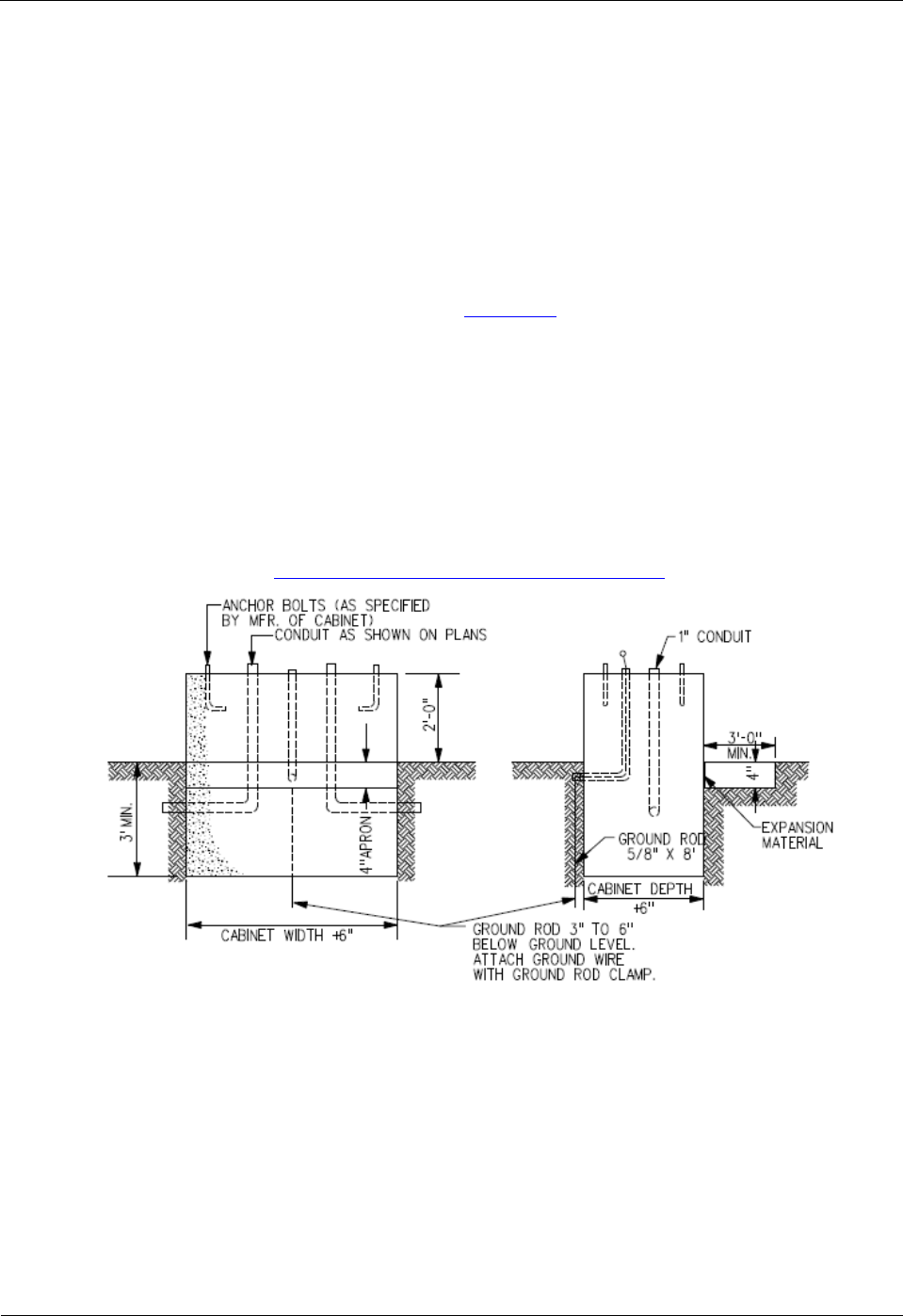
Section 13E-1 - Specifications Information
5
c. Wiring and cable. Signalized intersections require a variety of standard wires and cables,
however, the number, size, and quantity of extra conductors pulled can vary by agency. The
designer should include sufficient details to ensure the clear identification of cable runs by
conduit. The inspector should make sure all wires are terminated neatly and in an organized
fashion. With the exception of detector lead-in wires, no splices are allowed within
handholes. All plan terminology should be consistent for example:
• Cable symbols correct (3/C #12, 2/C #14, 3/C #20 all different, for example).
• Ped indications on different phases shall have separate 3/C #12 cables.
• Separate 2/C #14 for each detector.
• Provide spares for future expansion of system, if necessary, and label them.
An on-line resource can be found through
Chapter 14 Wiring (Mn/DOT’s 2009 Signal &
Lighting Certification Manual) which provides the designer with a photographic resource for
labeling and training wires (very Mn/DOT specific though).
d. Foundations. Signalized intersections require footings for all poles, controller pads, and
other service cabinets such as fiber optic hubs or electrical service panels. Controller footing
details are included for both the Type 170 and NEMA controller cabinets as shown in Figure
2 below. The designer should ensure that the plans reflect any desired future use spare
conduit stubs out of the footing.
Figure 2: NEMA Controller Cabinet Footing Detail
(SUDAS Standard Specifications Figure 8010.1)

Chapter 13 - Traffic Signals
6
Figure 3: Type 170 Controller Cabinet Footing Detail
(SUDAS Standard Specifications Figure 8010.2)
Footing size and depths vary according to pole style, mast-arm length, and pole loadings.
The SUDAS Standard Specifications provide figures for both pedestal poles (
SUDAS
Standard Specifications Figure 8010.11) and for mast-arm poles (SUDAS Standard
Specifications Figure 8010.7).
The designer should ensure that all foundations:
• Are located in compliance with applicable clear zone requirements
• Do not conflict with pedestrian walkways or ramps
• Are at the proper finish grade elevation
An online resource can be found through
Chapter 13 Concrete Foundations (Mn/DOT’s 2009
Signal & Lighting Certification Manual) which provides the designer with a photographic
resource for foundation types and installation details.
e. Bonding and Grounding. All traffic signal installations must be bonded and grounded
according to the National Electrical Code.
Bonding is defined in the Code Book as the permanent joining of metallic parts required to be
electrically connected. In a traffic signal, the term is used to describe the electrical and
mechanical connection of conduit, metal poles, cabinets, and service equipment.

Section 13E-1 - Specifications Information
7
Grounding is defined in the Code as a conducting connection, whether intentional or
accidental, between an electrical circuit or equipment and the earth, or to some conductive
body that serves in place of earth.
The designer should ensure that the contract documents include sufficient notation for the
traffic signalized intersection to be properly bonded and grounded. This includes placing
ground rods at each traffic signal pole and at the controller footing as well as through use of
bonding and grounding jumpers within the handholes.
An online resource can be found through
Chapter 12 Bonding and Grounding (Mn/DOT’s
2009 Signal & Lighting Certification Manual) which provides the designer with a
photographic resource for bonding and grounding details.
2. Detection. Detectors provide vehicle and pedestrian inputs to the traffic signal controller. Proper
detector installation, operation, and maintenance is critical to the safe and efficient operation of
any signalized intersection.
An online resource to learn more about detection styles, modes, and typical layouts can be found
within Chapter 4 Detection (
Traffic Engineering Manual). Since this document is a PDF, some of
the information from this source is provided below.
Detector sizes and locations vary by agency and by location. SUDAS provides a standard
drawing for a typical square detector loop (
SUDAS Figure 8010.5).
An on-line resource can be found through
Chapter 15 Detection (Mn/DOT’s 2009 Signal &
Lighting Certification Manual) which provides the designer with a photographic resource for
installation and mounting details.
a. Inductive loop vehicle detector. The most common type of vehicle detection device in use
today is the inductive loop. This is a loop of wire imbedded in the pavement (saw cut in
existing concrete or NMC loop in new concrete) carrying a small electrical current. When a
large mass of ferrous metal passes over the loop, the magnetic field is disturbed and
generates, or induces, a change in resonant frequency in the wire. This change in frequency
is then recognized by the detector amplifier and signals the controller that a vehicle is present.
b. Pedestrian push button detector. There are a number of ways to provide pedestrian
actuation at a signalized intersection. The most common equipment used by far is the
pedestrian pushbutton detector. Pressing the button provides a contact closure which actuates
the call. There are plenty of examples of good and bad pedestrian pushbutton placement,
however part problem is getting the pedestrian to use the button. Specific information
regarding pedestrian detectors can be found in the MUCTD Section
4E.08 Pedestrian
Detection.
An online resource can be found through
Chapter 19 Pedestrian Pushbuttons (Mn/DOT’s
2009 Signal & Lighting Certification Manual) which provides the designer with a
photographic resource for style, installation, and mounting details.
c. Video detection camera system. Vehicle detection by video cameras is a popular form of
vehicle detection within Iowa. The rapid processing of video images provides the detection
outputs to the controller. The designer should carefully consider the type of equipment
necessary to provide video detection, the maintenance needs of this equipment, and the
specific installation and mounting requirements necessary.

Chapter 13 - Traffic Signals
8
Designers should consider relevant manufacturer recommendations and other on-line
resources such as the
Guidelines for Using Video Detection at Intersections and Interchanges
by Bonneson at Texas Transportation Institute.
d. Microwave vehicle detector. Microwave detection is often used within Iowa during
temporary signal control to provide a simple non-intrusive vehicle detection. A variety of
styles and levels of sophistication exist in the market today.
3. Communications. The designer will be required to provide supplemental specifications for these
items given the highly proprietary nature of this equipment. Generic specification information
and supporting design guidance will be provided in future SUDAS efforts.
4. Cabinet and controller. The designer will be required to provide supplemental specifications
for the controller, cabinet, and emergency vehicle pre-emption system given the highly
proprietary nature of this equipment. Generic specification information and supporting design
guidance will be provided in future SUDAS efforts. New information was added to the
specification regarding uninterruptable power supply battery back-up system. The designer
should carefully consider the cabinet and mounting requirements of the batter back-up system.
An online resource can be found through
Chapter 22 Traffic Signal Cabinets (Mn/DOT’s 2009
Signal & Lighting Certification Manual) which provides the designer with a photographic
resource for style, installation, and mounting details.
5. Poles, heads, and signs.
a. Vehicle traffic signal head assembly. Vehicle signal heads must comply with the following
MUTCD sections:
Section 4D.16 Number and Arrangement of Signal Sections in Vehicular Traffic Control
Signal Faces
Section 4D.17 Visibility, Shielding, and Positioning of Signal Faces
Section 4D.18 Design, Illumination, and Color of Signal Sections
An online resource can be found through
Chapter 17 Traffic Signal Heads (Mn/DOT’s 2009
Signal & Lighting Certification Manual) which provides the designer with a photographic
resource for style, installation and mounting details.
b. Pedestrian signal head assembly. Pedestrian Vehicle signal heads must comply with the
following MUTCD sections:
Section 4E.01 Pedestrian Signal Heads
Section 4E.02 Meaning of Pedestrian Signal Head Indications
Section 4E.03 Application of Pedestrian Signal Heads
Section 4E.04 Size, Design, and Illumination of Pedestrian Signal Head Indications
Section 4E.05 Location and Height of Pedestrian Signal Heads
Section 4E.06 Accessible Pedestrian Signals
Section 4E.07 Countdown Pedestrian Signals
c. Traffic signal poles and mast arms. Signalized intersections require poles and mast arms to
achieve proper traffic signal and pedestrian head placement. Mast arm details and typical
loadings are shown in Figure 4. The designer should ensure that the plan locations comply
with all clear zone, sight restriction, and pedestrian flow criteria. Vertical clearance to

Section 13E-1 - Specifications Information
9
overhead utility lines is a constant issue that designers should take note of during pre-design
field activities.
Figure 4: Mast arm pole
(SUDAS Standard Specifications Figure 8010.17)
An online resource can be found through
Chapter 16 Mast Arm Poles and Pedestals
(Mn/DOT’s 2009 Signal & Lighting Certification Manual) which provides the designer with
a photographic resource for style, installation, and mounting details.
d. Traffic signal pedestal poles: Pedestal poles provide alternate mounting heights for signal
and pedestrian heads and are much easier to locate within a tight right-of-way. Pedestal pole
details and typical head mounting information is shown in Figure 5.
Figure 5: Pedestal pole
(SUDAS Standard Specifications Figure 8010.12)

Chapter 13 - Traffic Signals
10
e. Traffic signs. The designer must ensure that all signs comply with Iowa DOT standards and
the MUTCD. Figure 6 shows a mast arm sign bracket.
Figure 6: Mast arm sign bracket
(SUDAS Standard Specifications Figure 8010.10)
C. Items requiring supplemental specifications
A summary listing of items within the SUDAS Standard Specifications Section 8010 requiring
supplemental specifications to be provided by the designer includes the following:
• Composite Handhole and Cover – Specify materials and dimensions.
• Foundations – Specify foundation dimensions and any conduit stubs needed for future use.
• Communications- Specify all traffic monitoring equipment along with any fiber optic equipment
and materials.
• Cabinet, Controller, and Emergency Vehicle Preemption – Specify all relevant equipment.
• Traffic Signal Poles and Mast Arms – Specify specialty finish for pole if necessary.
• Traffic Signs – Specify sheeting, sign dimensions, and mounting requirements.

Traffic Signal Final Report
Division 8 - Traffic Signals
Specifications
Section 8010 - Traffic Signals
1
TRAFFIC SIGNALS
PART 1 - GENERAL
1.01 SECTION INCLUDES
A. Underground
B. Detection
C. Communications
D. Cabinet and Controller
E. Poles, Heads, and Signs
1.02 DESCRIPTION OF WORK
This part of the specifications includes the furnishing of all material and equipment necessary to
complete, in place and operational, traffic control signal(s) as described in the project plans.
1.03 SUBMITTALS
Follow the General Provisions (Requirements) and Covenants as well as the following:
A. Schedule of Unit Prices: Within 30 days after awarding of the contract for the project,
submit a completed schedule of unit prices. Estimates of the work performed on the project
will be made by the Jurisdiction and the unit costs will be used to prepare progress payments
to the Contractor.
B. Material and Equipment List: Within 30 days after awarding of the contract for the project,
submit a completed list of materials and equipment. Submit six copies to the Jurisdiction for
written approval before any equipment or materials are ordered.
C. Contractor Certification: Submit the name and contact information of the International
Municipal Signal Association (IMSA) Level II Certified Traffic Signal Technician(s) working on
the project and a copy of their IMSA certificate.
D. Shop Drawings: Submit six copies of shop drawings for traffic signal poles and structures to
be furnished on the project. Submit six copies of catalog cuts and manufacturer’s
specifications for all items in the equipment list.
1.04 SUBSTITUTIONS
Follow the General Provisions (Requirements) and Covenants.
1.05 DELIVERY, STORAGE, AND HANDLING
Follow the General Provisions (Requirements) and Covenants.
1.06 SCHEDULING AND CONFLICTS
Follow the General Provisions (Requirements) and Covenants.
1.07 SPECIAL REQUIREMENTS
None.

Traffic Signal Final Report
Division 8 - Traffic Signals
Specifications
Section 8010 - Traffic Signals
2
1.08 MEASUREMENT AND PAYMENT
A. Traffic Signal:
1. Measurement: Lump sum item; no measurement will be made.
2. Payment: Payment will be at the lump sum price for traffic signal installation.

Traffic Signal Final Report
Division 8 - Traffic Signals
Specifications
Section 8010 - Traffic Signals
3
PART 2 - PRODUCTS
2.01 UNDERGROUND
A. Handhole:
1. General:
a. Cable Hooks: Galvanized steel cable hooks with a minimum diameter of 3/8 inch
and a minimum length of 5 inches.
b. Granular Base: Processed gravel or crushed stone complying with Iowa DOT 4109,
Gradation No. 3.
2. Precast Concrete Handhole:
a. Pipe: Comply with ASTM C 76. Minimum Class III, Wall B (Iowa DOT Class
2000D). Four, 8 inch knockouts (conduit entrance points) equally spaced around the
handhole and at the half the depth of the handhole.
b. Casting: Gray cast iron and certified according to requirements of AASHTO M 306
for a 16,000 pound proof-load (HS-20).
3. Composite Handhole and Cover: Composed of mortar consisting of sand, gravel, and
polyester resin reinforced by a woven glass fiber mat or of resin mortar and fiberglass.
Ensure the handhole and cover withstands a load of 20,000 pounds. Provide a skid
resistant surface on the cover.
B. Conduit:
1. General:
a. Furnish weatherproof fittings of identical or compatible material to the conduit. Use
standard factory elbows, couplings, and other fittings.
b. Use a manufactured conduit sealing compound that is readily workable material at
temperatures as low as 30°F and will not melt or run at temperatures as high as
300°F.
2. Steel Conduit and Fittings:
a. Comply with ANSI C80.1.
b. Use weatherproof expansion fittings with galvanized, malleable iron, fixed and
expansion heads jointed by rigid steel conduit sleeves. As an option, the fixed head
may be integral with the sleeve, forming a one piece body of galvanized malleable
iron.
c. Provide steel bushings.
3. Plastic Conduit and Fittings:
a. PVC:
1) PVC Schedule 40 plastic conduit and fittings complying with NEMA TC-2 (pipe),
NEMA TC-3 (fittings), and UL 651 for Schedule 40 heavy wall type.
2) Solvent welded, socket type fittings, except where otherwise specified in the
contract documents.
3) Threaded adaptors for jointing plastic conduit to rigid metal ducts.
4) Provide bell end fittings or bushings.
b. HDPE:
1) Comply with ASTM F 2160 (conduit) and ASTM D 3350 (HDPE material), SDR
13.5.
2) Use orange colored conduit.
3) Continuous reel or straight pieces to minimize splicing.
4) For dissimilar conduit connections, provide an adhesive compatible with both
materials.

Traffic Signal Final Report
Division 8 - Traffic Signals
Specifications
Section 8010 - Traffic Signals
4
2.01 UNDERGROUND (Continued)
C. Wiring and Cable: Provide wire that is plainly marked on the outside of the sheath with the
manufacturer's name and identification of the type of the cable.
1. Power Cable: Comply with Iowa DOT Article 4185.12.
2. Signal Cable: Comply with IMSA Specifications 19-1 (PVC jacket) or 20-1 (polyethylene
jacket) for polyethylene insulated, 600 volt, solid, multi-conductor copper wire, #14
American Wire Gauge (AWG).
3. Tracer Wire: Comply with #10 AWG, single conductor, stranded copper, Type
thermoplastic high-heat nylon-coated (THHN), with UL approval, and an orange colored
jacket.
4. Communications Cable: Comply with IMSA Specifications 39-2 or 40-2 for #19 AWG,
solid copper conductor, twisted pairs. Use polyethylene insulated, aluminum shielded,
complying with REA Specification PE-39 for paired communication cable with electrical
shielding.
5. Category 5E (Cat5E) Cable: Provide outdoor use rated cable.
6. Fiber Optic Cable and Accessories: As allowed by the Jurisdiction or specified in the
contract documents.
D. Foundations:
1. Use Class C structural concrete complying with Iowa DOT Section 2403.
2. Use reinforcing steel complying with Iowa DOT Section 2404.
E. Bonding and Grounding:
1. Grounding Rods: Provide 5/8 inch by 8 foot copper clad, steel ground rod at each pole
and controller footing.
2. Bonding Jumper or Connecting Wire: Provide #6 AWG bare conductor, copper wire.
2.02 DETECTION
A. Inductive Loop Vehicle Detector: A detector consists of a conductor loop or series of loops
installed in the roadway, lead-in (feeder) cable, and a sensor (amplifier) unit with power
supply installed in a traffic signal controller cabinet.
1. Cables: All cables must be UL approved.
a. Tube Loop Detector Cable: Comply with IMSA Specifications 51-5.
b. Preformed Loop Detector Cable: As approved by the Engineer.
c. Loop Detector Lead-in Cable: Comply with IMSA Specifications 50-2.
2. Detector Loop Sealant:
a. Use a rapid cure, high viscosity, liquid epoxy sealant formulated for use in sealing
inductive wire loops and leads embedded in pavement. Ensure the cured sealer is
unaffected by oils, gasoline, grease, acids, and most alkalis.
b. Use a sealant complying with Iowa DOT Materials I.M. 491.18.

Traffic Signal Final Report
Division 8 - Traffic Signals
Specifications
Section 8010 - Traffic Signals
5
2.02 DETECTION (Continued)
3. Sensor (Amplifier) Unit:
a. Use a sensor unit that is solid state, digital, providing detection channel(s) with an
inductance range of 0 to 2,000 micro-henries. Output circuits of the sensor unit will
be provided by relays. Vehicle presence will result in a continuous call indication.
b. Provide a sensor unit with the following qualities:
1) Sensitivity adjustment to allow as a minimum the selection of high, medium, or
low sensitivity.
2) Be capable of providing reliable detection of all licensed motor vehicles.
3) Provide an indicator light for visual indication of each vehicle detection.
4) Will not require external equipment for tuning or adjustment.
5) Provide operation in the pulse mode or presence mode. Ensure mode switch is
readily accessible.
6) Provide a self tuning system that is activated automatically with each application
of power. Provide automatic and continuous fine tuning to correct for
environmental drift of loop impedance.
7) Provide for fail-safe operation (continuous call) in the event of detector loop
failure.
8) Ensure each detector channel will respond to a frequency shift in an increasing
or decreasing value as occurs with temperature shifts in the pavement without
requiring a locked call.
9) Use detector units with delay and extension timing. The delay feature is selected
and adjusted externally on the sensor unit housing. Digitally derived timing is
selectable in 1 second increments from 0 to 30 seconds. Ensure delay timing
inhibits detector output until presence has been maintained for the time selected.
Restart delay timer at each new detection.
10) Use a sensor unit capable of normal operation without interference and false
calls between sensor units ("crosstalk") when installed in the physical
environment of the controller cabinet and the electrical environment of the
associated electronic equipment installed therein, including other detectors.
B. Pedestrian Push Button Detector:
1. Assembly:
a. Ensure the entire assembly is weather tight, secure against electrical shock,
withstands continuous hard usage.
b. Provide a removable contact assembly mounted in a die cast aluminum case.
c. Ensure contacts are normally open with no current flowing except at the moment of
actuation.
d. Ensure the contacts are entirely insulated from the housing and operating button with
terminals for making connections.
e. Provide housing with one outlet for 1/2 inch pipe.
2. Operating Button:
a. Nonrusting metal alloy.
b. Ensure the button does not protrude out from the case.
c. Supply ADA compliant operating button.
3. Signs: Furnish push button signs complying with MUTCD.
C. Video Detection Camera System: Detects vehicles by processing video images and
providing detection outputs to the traffic signal controller.
1. Video Detection System and Processors:
a. Processor to be card rack mounted or located within camera. Compatible with NEMA
TS-1, TS-2, and Type 170 controllers and cabinets.

Traffic Signal Final Report
Division 8 - Traffic Signals
Specifications
Section 8010 - Traffic Signals
6
2.02 DETECTION (Continued)
b. Must be capable of the following:
1) Shadow rejection without special hardware.
2) Non-impaired operation under light intensity changes.
3) Maintained operation during various weather conditions (e.g. rain, fog, snow).
4) Anti-vibration, 5% rejection based on image change.
5) Proper operation during sunrise and sunset.
6) Ability to select direction of flow parameters.
7) Ability to properly detect bi-directionally.
8) Operate in presence mode with less than 4% error.
c. Provide user-defined detection zone programming via a graphical user interface
(GUI) using a monitor and mouse, or laptop computer. Store detection zones in non-
volatile memory. Provide monitor and mouse, or computer software to the
Jurisdiction.
d. Comply with NEMA TS-1 environmental and physical standards with an operating
temperature of -34°C to +74°C, and 0% to 95% relative humidity.
e. Ensure a factory certified representative from the supplier provides on-site VDS
programming and testing.
2. Video Cameras:
a. Provide a charge-coupled device (CCD) image sensor with variable focus color or
black and white lens providing 6 to 48 degree horizontal field of view.
b. Equipped with internal thermostatically controlled heater and external sunshield.
c. Meet NEMA-4 or NEMA-6P environmental standards.
d. Use camera cable(s) meeting the manufacturer’s recommendations. Provide a
continuous run, without splices, from the camera to the controller cabinet.
D. Microwave Vehicle Detector: Detects all vehicles moving within the field of detection at
speeds from 2 to 80 mph.
1. Must be capable of the following:
a. Minimum detection range from 3 to 200 feet for all vehicles.
b. Pattern spread of the detection field no more than 16 degrees.
c. Self-tuning and capable of continuous operation over a temperature range of -35° F
to 165° F.
d. Side-fire mount or overhead mount.
e. Detecting directional traffic and the direction user selectable.
2. Microprocessor based using Doppler microwave at an operating frequency of 10.525
GHz.
3. FCC certification and tested to the applicable FCC specifications.
4. Enclosure constructed of aluminum or stainless steel and water resistant.
5. All user operated controls and adjustments must be clearly marked and easily accessible.
6. Relay detection output to the controller with a minimum 5 amp rating and designed to
place a constant call to the controller in the event of any failure.
7. Easily accessible indicator showing activation of detection relay.
8. Required wiring as specified by the manufacturer.
9. Provide mounting hardware for the type of mounting specified in the contract documents
and power supply equipment as recommended by the manufacturer.

Traffic Signal Final Report
Division 8 - Traffic Signals
Specifications
Section 8010 - Traffic Signals
7
2.03 COMMUNICATIONS
A. Traffic Monitoring System: As specified in the contract documents.
B. Fiber Optic Hub Cabinet: As specified in the contract documents.
C. Wireless Interconnect Network: Provides two-way data communication between the on-
street master controller and local traffic signal controllers.
1. Data Transceiver:
a. Utilize a license-free spread spectrum radio frequency (902-928 MHZ) with frequency
hopping technology.
b. Completely programmable by software. Furnish software to the Jurisdiction.
c. Built-in diagnostics capabilities.
d. Configurable as master, slave, or repeater with store and forward capability.
e. Maintains user selectable power output levels between 0.1 and 1 watt.
f. Operates with input voltages between 6 VDC and 30 VDC.
g. RS-232 interface with 115.2 kbps capability.
h. Operating temperature of -40°C to +75°C.
i. Receiver sensitivity of -108 to -110 dBm at 10
-6
BER.
j. Protected from power surges.
k. Rack or shelf mounted in controller cabinet and connections for antenna, power, and
controller.
2. Antenna:
a. Capable of transmitting and receiving data between intersections.
b. Mount near the top of the signal pole nearest the controller cabinet or as specified in
the contract documents. Provide engineer-approved mounting hardware.
c. Connect to transceiver via appropriate cable from pole to signal cabinet in same
conduit as traffic signal cable. Conceal cable within a watertight connection at
antenna.
2.04 CABINET AND CONTROLLER
A. Controller Cabinet and Auxiliary Equipment: As specified in the contract documents.
B. Controller: As specified in the contract documents.
C. Uninterruptible Power Supply Battery Backup System: Monitors 120VAC input from the
electric utility source and automatically switches to/from a system consisting of batteries and
electronics.
1. Include a maintenance bypass switch to allow operation of the traffic signal system while
repairs are made to the battery backup system.
2. Designed to provide a minimum of 4 hours of normal operation.
3. Use cabinet equipment that is plug connected and shelf mounted.
4. Designed to cover a temperature range from -30°F to +165°F and include a surge
suppressor wired to the input from utility power.
D. Emergency Vehicle Preemption System: As specified in the contract documents.

Traffic Signal Final Report
Division 8 - Traffic Signals
Specifications
Section 8010 - Traffic Signals
8
2.05 POLES, HEADS, AND SIGNS
A. Vehicle Traffic Signal Head Assembly: Comply with current MUTCD and ITE standards.
1. Housing:
a. Individual signal sections made of a durable polycarbonate. Use color specified in
the contract documents. Color to be an integral part of the materials composition.
b. Self-contained unit capable of separate mounting or inclusion in a signal face
containing two or more signal sections rigidly and securely fastened together.
c. Equipped with openings and positive locking devices in the top and bottom so that it
may be rotated between waterproof supporting brackets capable of being directed
and secured at any angle in the horizontal plane.
d. Doors and lenses with suitable watertight gaskets and doors that are suitably hinged
and held securely to the body of the housing by simple locking devices of non-
corrosive material. Doors are to be easily removed and reinstalled without use of
special tools.
2. Optical System: Designed to prevent any objectionable reflection of sun rays even at
times of the day when the sun may shine directly into the lens.
3. Lenses: 12 inch diameter polycarbonate. Do not use glass lenses.
4. Visors:
a. Standard Installation:
1) Each signal lens is to have a visor with the bottom 25% open.
2) Minimum 0.1 inch in thickness and black in color.
3) Fits tightly against the housing door with no filtration of light between the visor
and door.
4) Minimum length of 9 1/2 inches. Ensure the visor angle is slightly downward.
b. Optically Programmed Sections: Make sure the optical unit and visor are designed
as a whole to eliminate the return of outside rays entering the unit from above the
horizontal.
5. Terminal Block:
a. Three-section signal equipped with a six position terminal block.
b. Four- and five-section signal equipped with an eight position terminal block.
6. Backplate:
a. Manufactured one-piece, durable, black plastic capable of withstanding a 100 mph
wind.
b. Provides 5 inches of black field around the assembly.
7. Mounting Hardware:
a. Fixed: 1 1/2 inch aluminum pipe and fittings, natural aluminum finish for galvanized
poles or match the pole color. Secure to pole with a minimum 5/8 inch wide stainless
steel banding material.
b. Universally Adjustable: Rigid mounted, consisting of both top and bottom brackets
and easily adjustable in both horizontal and vertical planes.
8. LED Modules: Comply with current ITE standards.

Traffic Signal Final Report
Division 8 - Traffic Signals
Specifications
Section 8010 - Traffic Signals
9
2.05 POLES, HEADS, AND SIGNS (Continued)
B. Pedestrian Traffic Signal Head Assembly: Comply with current MUTCD and ITE
standards.
1. Housing:
a. Made of a durable polycarbonate. Use color specified in the contract documents.
Color to be an integral part of the materials composition.
b. Self-contained unit capable of separate mounting or inclusion in a signal face
containing one or more signal sections rigidly and securely fastened together.
c. Equipped with openings and positive locking devices in the top and bottom so that it
may be rotated between waterproof supporting brackets capable of being directed
and secured at any angle in the horizontal plane.
d. Doors and lenses with suitable watertight gaskets and doors that are suitably hinged
and held securely to the body of the housing by simple locking devices of non-
corrosive material. Doors are to be easily removed and reinstalled without use of
special tools.
2. Visor:
a. Tunnel type visor attached to the housing door by stainless steel screws.
b. Minimum of 7 inches in length.
c. Encompass the entire top and sides (bottom open) of the pedestrian signal face and
fit tightly against the housing door to prevent any perceptible filtration of light between
the door and the visor. Ensure the visor angle is slightly downward.
3. LED Module:
a. Provide a LED unit(s) for the filled upraised hand symbol, walking person symbol,
and countdown timer.
b. Ensure immediate blank out of the countdown timer display upon recognizing a
shortened “Walk” or a shortened "Flashing Don't Walk" interval.
C. Traffic Signal Poles and Mast Arms:
1. General:
a. Comply with AASHTO Standard Specifications for Structural Supports for Highway
Signs, Luminaries, and Traffic Signals.
b. Designed to support the loading necessary for all traffic control equipment. Capable
of withstanding winds up to 80 MPH with a 1.3 gust factor without failure.
c. Mast arm length and vertical pole height as specified in the contract documents.
d. Ensure the mast arms, poles, and supporting bases are galvanized inside and out
according to ASTM A 123.
e. Continuous tapered, round, steel poles of the transformer base type. Fabricated from
low carbon (maximum carbon 0.30%) steel of U.S. standard gauge.
f. When a transformer base is not specified, provide a 6 inch by 16 inch handhole in the
pole shaft for cable access. Provide a cover for the handhole. Secure the cover to
the base with simple tools. Hardware to be corrosion resistant.
g. Ensure minimum yield strength of 48,000 psi after manufacture. Supply base and
flange plates of structural steel complying with AASHTO M 183 (ASTM A 36) and
cast steel complying with ASTM A 27, Grade 65-35 or better.
h. Where a combination street lighting/signal pole is specified in the contract
documents, the luminaire arm is to be mounted in the same vertical plane as the
signal arm unless otherwise specified. Use a single member tapered type arm for the
luminaire arm type. Equip the pole with a minimum 4 inch by 6 inch handhole and
cover located opposite the signal mast arm.

Traffic Signal Final Report
Division 8 - Traffic Signals
Specifications
Section 8010 - Traffic Signals
10
2.05 POLES, HEADS, AND SIGNS (Continued)
i. If allowed by the Engineer, poles and mast arms may be fabricated by welding two
sections together, resulting in a smooth joint and factory welded as follows:
1) Ensure a minimum of 60% penetration for plates 3/8 inch and less in thickness
for longitudinal butt welds, except within one foot of a transverse butt-welded
joint. Ensure a minimum of 80% penetration for plates over 3/8 inch in thickness.
2) Ensure 100% penetration for longitudinal butt welds on poles and arms within
one foot of a transverse butt-welded joint.
3) Ensure 100% penetration, achieved by back-up ring or bar, for transverse butt
welds for connecting.
4) Examine 100% of transverse butt welds and 100% penetration longitudinal butt
welds by ultrasonic inspection according to the requirements of AWS D1.1-
80.AH.
5) Comply with Structural Welding Code AWS D1-180, as modified by AASHTO
1981 Standard Specifications for Welding of Structural Steel Highway Bridges
and by Supplemental Specifications No. 969.
2. Hardware:
a. Equipped with all necessary hardware and anchor bolts to provide for a complete
installation without additional parts.
b. Anchor bolts complying with ASTM A 36, hot dip galvanized and threaded a minimum
of 6 inches at one end and have a 4 inch long, 90 degree bend at the other end.
c. Washers complying with ASTM F 436.
d. Heavy hex nuts complying with ASTM A 563.
e. All hardware made of steel, hot dipped galvanized complying with ASTM A 153, or
electrodeposited coated of the same coating thickness and designed for this
purpose.
D. Traffic Signal Pedestal Poles:
1. Materials:
a. Pedestal: The length from the bottom of the base to the top of the shaft as specified
in the contract documents.
b. Pedestal Shaft: Schedule 80 with satin brush or spun finish aluminum tubing. Top
of the shaft outer diameter to be 4 1/2 inches and provided with a pole cap. Supply
base collar for poles with shaft lengths greater than 10 feet.
c. Pedestal Base: Cast aluminum, square in shape, with a handhole.
1) Handhole: Minimum of 6 inches by 6 inches and equipped with a cast aluminum
cover that can be securely fastened to the base with the use of simple tools.
2) Base: Minimum weight of 20 pounds with a four bolt pattern uniformly spaced on
a 12 1/2 inch diameter bolt circle. Meet or exceed AASHTO breakaway
requirements.
2. Anchor Bolts: Four 3/4 inch by 15 inch steel, hot dip galvanized anchor bolts with right
angle bend at the bottom end, complete with all hardware required for installation.
E. Traffic Signs:
1. Comply with Iowa DOT Section 4186.
2. Use a universally adjustable mast arm mounted sign bracket.
3. Comply with MUTCD and the contract documents for the street name sign dimensions,
letter height and font, and sheeting.

Traffic Signal Final Report
Division 8 - Traffic Signals
Specifications
Section 8010 - Traffic Signals
11
PART 3 - EXECUTION
3.01 UNDERGROUND
A. Handhole
1. Locations:
a. Do not construct in ditch bottoms, low areas where ponding of water may occur, or
where they will be subject to normal vehicular traffic.
b. With Engineer approval, additional handholes may be placed, at no additional cost to
the Contracting Authority, to facilitate the work.
2. Excavation: Excavate as necessary to accommodate the handhole and granular base.
3. Granular Base: Install 8 inch thick granular base extending a minimum of 6 inches
beyond the outside walls of the handhole.
4. Placement:
a. In paved areas, install the handhole at an elevation so the casting is level and flush
with the pavement. In unpaved areas, install the handhole approximately 1 inch
above the final grade.
b. Verify ring placement. Invert rings when installed in paved areas.
5. Conduit:
a. Remove knockouts as necessary to facilitate conduit entrance.
b. Extend conduit into the handhole, through a knockout, approximately 2 inches
beyond the inside wall. Conduit to slope down and away from the handhole.
c. Place non-shrink grout (complying with Iowa DOT Materials I.M. 493.13) in the
opening of the knockout area after placement of conduit.
d. Cut conduit ends within the handhole at 90 degrees.
6. Cable Hooks: Install cable hooks centered between the knockouts and the top of the
handhole.
7. Backfill: Place suitable backfill material according to Section 3010.
8. Casting: Place the casting on the handhole. Ensure the final elevation meets the
handhole placement requirements.
B. Conduit
1. General:
a. Place conduit to a minimum depth of 30 inches and a maximum depth of 60 inches
below the gutterline. When conduit is placed behind the curb, place to a minimum
depth of 24 inches and a maximum depth of 36 inches below top of curb.
b. Change direction at handholes or by bending, such that the conduit will not be injured
or its internal diameter changed. Ensure bends are uniform in curvature and the
inside radius of curvature of any bend is no less than six times the internal diameter
of the conduit.
c. On the exposed ends of conduit, place bell-end fittings on PVC or HDPE conduit and
bushings on steel conduit prior to installing cable. Extend all conduits a minimum of
2 inches and a maximum of 4 inches above the finished surface of any footing or
structural base.

Traffic Signal Final Report
Division 8 - Traffic Signals
Specifications
Section 8010 - Traffic Signals
12
3.01 UNDERGROUND (Continued)
d. When it is necessary to cut and thread steel conduit, do not allow exposed threads.
Ensure conduits and fittings are free from burrs and rough places. Clean, swab, and
ream conduit runs before cables are installed. Use nipples to eliminate cutting and
threading where short lengths of conduit are required. Coat damaged galvanized
finish on conduit with zinc rich paint. Use only galvanized steel fittings with steel
conduit.
e. Pack conduit ends with a conduit sealing compound.
2. Trenched Installation:
a. Place backfill in layers not to exceed 12 inches in depth with each layer thoroughly
compacted before the next layer is placed. Ensure backfill material is free of cinders,
broken concrete, or other hard or abrasive materials.
b. Remove all surplus material from the public right-of-way as soon as possible.
3. Trenchless Installation:
a. When placing conduit under pavements, use the trenchless installation methods
described in Section 3020.
b. If trenchless methods that compact soils in the bore path are used, provide sufficient
cover to prevent heaving of overlying paved surfaces.
c. Do not allow pits for boring to be closer than 2 feet to the back of curb, unless
otherwise specified in the contract documents.
C. Wiring and Cable:
1. Where practical, follow color codes so that the red insulated conductor connects to the
red indication terminal, yellow to yellow, and green to green. Ensure cables are properly
labeled at the controller by durable labels, or other appropriate methods, attached to the
cables. Label home runs for cables as follows: northwest corner is red, southeast corner
is blue, northeast corner is green, and southwest corner is orange.
2. Install continuous runs of vehicle and pedestrian signal cables from the vehicle or
pedestrian signal head to the handhole compartment of the signal pole base. Install
continuous runs of vehicle and pedestrian signal cables from the handhole compartment
of the signal pole base to the terminal compartment in the controller cabinet. Do not
splice signal cables in underground handholes.
3. Install continuous runs for video detection and emergency vehicle preemption cables
from the unit to the controller cabinet.
4. Install continuous runs of power lead-in cables from the service point to the meter socket
and from the meter socket to the controller cabinet.
5. Install continuous detector cable from each detector loop to the first handhole adjacent to
the loop. Ensure cables are properly labeled at the controller by durable labels, or other
appropriate methods, attached to the cables. Install continuous homerun cable from the
splice made in the first handhole to the terminal compartment in the controller cabinet.
Attach the drain wire of the shielded cable to the ground in the controller cabinet.
6. Provide a minimum of 4 feet of additional cable at each handhole and loosely coil the
extra cable on the handhole cable hooks. Provide a minimum of 2 feet of additional cable
at each signal pole (measured from the handhole compartment in the pole to the end of
the cable). Provide a minimum of 10 feet of additional cable at each controller base.
7. Pull cables through conduit using a cable grip designed to provide a firm hold upon the
exterior covering of the cable or cables, and minimize dragging on the ground or
pavement.

Traffic Signal Final Report
Division 8 - Traffic Signals
Specifications
Section 8010 - Traffic Signals
13
3.01 UNDERGROUND (Continued)
8. Install a tracer wire in all conduits with the exception of conduits between detector loops
and handholes. Use a silicon-filled wire nut to splice the tracer wire in each handhole
and at the controller to form a continuous run.
D. Foundations:
1. Excavation: Excavate to the size, shape, and depth specified in the contract
documents. Ensure the bottom of all foundations rest securely on firm undisturbed soil.
Minimize overexcavation to ensure support and stability of the foundation.
2. Footing: Provide a means for holding all of the following elements rigidly in place while
the concrete is being placed.
a. Forms:
1) Set the forms level or sloped to meet the adjacent paved areas.
2) When adjacent to paved areas, shape the top 10 inches of the footing to be
square and flush with the surrounding paved area. Provide preformed expansion
material between the footing and paved areas.
3) When installed in an unpaved area, set the top of the footing 2 inches above the
surface of the ground.
b. Reinforcing Steel: Install reinforcing steel.
c. Conduit: Install conduit.
d. Anchor Bolts:
1) Set anchor bolts using a template constructed to accommodate the specified
elevation, orientation, and spacing according to the pole and controller
manufacturer's requirements.
2) Center the pole anchor bolts within the concrete footing.
3) Protect the anchor bolts until poles are erected.
4) Orient controller footing with the back of the cabinet toward the intersection such
that the signal heads can be viewed while facing the controller, unless otherwise
directed by the Engineer.
e. Concrete:
1) Place concrete to form a monolithic foundation. Consolidate concrete by
vibration methods.
2) Finish the top of the base level and round the top edges with an edging tool
having a radius of 1/2 inch. Provide a rubbed surface finish on the exposed
surface of the footing.
3) Allow the footings to cure a minimum of 4 days prior to erecting the poles and 7
days prior to installing the mast arms. Times may be shortened if supported by
strength test results.
3. Backfill: Place suitable backfill material according to Section 3010.
E. Bonding and Grounding:
1. Ensure the traffic signal installation is grounded as required by the National Electric
Safety Code.
2. Install a ground rod at each signal pole and controller footing.
3. Use PVC conduit within the footing to accommodate the connection between the top of
the footing and the grounding rod.
4. Bond poles to ground rods with copper wire. Connect ground wires to ground rods with
approved mechanical connectors.
5. Bond rigid steel conduit ends in handholes with copper wire and approved fittings.

Traffic Signal Final Report
Division 8 - Traffic Signals
Specifications
Section 8010 - Traffic Signals
14
3.02 DETECTION
A. Detector Loop Cable Installation:
1. Coordinate the location of the detector loop with the Engineer. Obtain the Engineer’s
approval prior to cutting the pavement.
2. Saw to ensure proper depth and alignment of the slot. Make a 2 inch deep clean,
straight, well-defined 3/8 inch wide saw cut without damage to adjacent areas. Overlap
the saw cuts where the detector loop changes direction to provide full depth at all
corners. Do not use right angle or corners less than 90 degrees.
3. Before installing the detector loop cable, check the saw cuts for the presence of jagged
edges or protrusions and remove if present. Clean and dry the saw cuts to remove
cutting dust, grit, oil, moisture, or other contaminants. Clean by flushing with a stream of
water under pressure. Use oil-free compressed air to dry the saw cuts.
4. Install detector loop cable without damage. Place three turns of the detector loop cable
into the saw cut. Seal the ends of the tubing at the time of placement to prevent entrance
of moisture.
5. Ensure the detector loop cables are in the bottom of the saw cut. Place detector loop
sealant within the saw cut area. Comply with the manufacturer’s instructions for mixing
and using the detector loop sealant.
6. Identify each detector loop cable in the handhole by phase and location. Wind loops that
are physically adjacent in an individual lane or adjacent lanes with opposite rotation (i.e.
#1 clockwise, #2 counter-clockwise, #3 clockwise, etc.). Rotation reversal can be
accomplished by reversing leads at the handhole.
7. Twist, with at least five turns per foot, all lengths of loop wires and tubing that are not
embedded in the pavement.
8. Identify all detector loop lead-in cables with appropriate detector numbers.
9. Use a detector loop cable splice kit for the electrical splice between the detector loop
cable and the detector loop lead-in cable to the controller.
a. Ensure splice kit provides a watertight protective covering for the spliced wire, the
shielding on the detector loop lead-in cable, and the end of the tubing containing the
detector loop cable.
b. Use a manufactured electrical splice kit approved by the Engineer.
10. Test all loops and document by using the following procedures:
a. Determine the insulation resistance of the loop wire using a "megger" with 500V
applied to either loop wire to earth ground. The resistance is to be greater than 100
megohms.
b. Determine the inductance of the loop using a loop inductance meter.
B. Pedestrian Push Button Detectors:
1. Install according to the manufacturer’s recommendations.
2. Seal the wire entrance into the pedestrian push button assembly.
C. Video Detection Camera System: Install according to the manufacturer’s recommendations
and as specified in the contract documents.

Traffic Signal Final Report
Division 8 - Traffic Signals
Specifications
Section 8010 - Traffic Signals
15
3.03 COMMUNICATIONS
A. Traffic Monitoring System: Install according to the manufacturer’s recommendations and
as specified in the contract documents.
B. Fiber Optic Hub Cabinet: Install according to the manufacturer’s recommendations and as
specified in the contract documents.
3.04 CABINET AND CONTROLLER
A. Controller Cabinet and Auxiliary Equipment:
1. Install according to the manufacturer’s recommendations and as specified in the contract
documents.
2. Install on pre-placed caulking material on the concrete base. After the cabinet is installed
in place, place caulking material around the base of the cabinet.
B. Controller: Install according to the manufacturer’s recommendations and as specified in the
contract documents.
C. UPS Battery Backup System: Install according to the manufacturer’s recommendations
and as specified in the contract documents.
D. Emergency Vehicle Preemption System: Install according to the manufacturer’s
recommendations and as specified in the contract documents.
3.05 POLES, HEADS, AND SIGNS
A. Vehicle and Pedestrian Traffic Signal Heads:
1. Inspect each signal head assembly while still on the ground for the following:
a. Physical defects
b. Visor type
c. LED wattage
d. Lens orientation
e. Wiring connections
2. Attach signal head mounting hardware according to the manufacturer’s
recommendations. Apply anti-seize compound to all mechanical fasteners.
3. Adjust each signal head both vertically and horizontally to approximate a uniform grade of
all like signal heads.
4. During the course of construction and until the signals are placed in operation, cover
signal faces or turn away from approaching traffic. When ready for operation, plumb and
aim the heads.
B. Traffic Signal and Pedestal Poles:
1. Erect all poles vertically under normal load.
2. Securely bolt the bases to the cast-in-place concrete foundations.
a. Mast Arm Poles: Level by using two nuts on each anchor bolt or according to the
manufacturer’s recommendations.
b. Pedestal Poles: Level by using metal shims and one nut on each anchor bolt or
according to the manufacturer’s recommendations.

Traffic Signal Final Report
Division 8 - Traffic Signals
Specifications
Section 8010 - Traffic Signals
16
3.05 POLES, HEADS, AND SIGNS (Continued)
3. After leveling the poles, use non-shrink grout (complying with Iowa DOT Materials I.M.
493.13) or 1/4 inch square banded galvanized hardware cloth between the pole base and
the foundation. Neatly finish exposed edges of grout to present a pleasing appearance.
Place a weep hole in the grout.
4. Apply anti-seize compound to all mechanical fasteners on pole access doors.
C. Traffic Signs: Install signs using universally adjustable sign brackets banded to the pole.
Apply anti-seize compound to all mechanical fasteners.
3.06 SURFACE RESTORATION
A. Replace or reconstruct features removed as a part of the work, such as sidewalks, driveways,
curbs, roadway pavement, unpaved areas, or any other items.
B. Complete restoration according the applicable sections of the SUDAS Standard
Specifications or as directed by the Engineer.
3.07 TESTING
A. Notify the Engineer 48 hours in advance of the time and date the signal or signal system will
be ready for turn on. Do not turn on the signal or signal system without authorization of the
Engineer.
B. Ensure a representative from the manufacturer and/or supplier of signal controller or other
authorized person is at the project site when the signal controllers are ready to be turned on
to provide technical assistance including, as a minimum, programming of all necessary input
data.
C. All required signal timing data will be provided by the Engineer.
D. A test period of 30 calendar days will start upon confirmation from the Engineer that the
signal or signal system is operating consistent with the project requirements. Any failure or
malfunction of the equipment furnished by the Contractor, occurring during the test period will
be corrected by the Contractor at no additional cost to the Contracting Authority. Upon
confirmation by the Engineer that any failure or malfunction has been corrected, a new test
period of 30 calendar days will start, exclusive of minor malfunctions such as lamp burnouts.
Repeat this procedure until the signal equipment has operated satisfactorily for 30
consecutive calendar days.
E. After signal turn on and prior to completion of the 30 calendar day test period, respond, within
24 hours, to perform maintenance or repair of any failure or malfunction reported.
3.08 DOCUMENTATION
A. Provide file documentation packages with each signal system, consisting of the following:
1. Complete cabinet wiring diagram.
2. Complete physical description of the equipment.
3. Controller printout or equal documentation of initial controller settings installed in the field
or in the office.
4. Product manuals for all cabinet equipment.

Traffic Signal Final Report
Division 8 - Traffic Signals
Specifications
Section 8010 - Traffic Signals
17
3.08 DOCUMENTATION (Continued)
5. Standard industry warranties on equipment supplied.
6. Documentation of field cable labeling scheme.
7. Diagram of phasing and detector locations.
8. One set of construction plans.
B. Supply two complete sets of documentation. One set to be placed in the controller cabinet
and the other set (less construction plan) to be delivered to the Engineer.
END OF SECTION
