AEROSPACE REPORT NO.
TOR-2010(8591)-16
Space Vehicle Testbeds and Simulators Taxonomy and
Development Guide
June 30, 2010
Tzvetan S. Metodi
Computer Science and Technology Subdivision
Computers and Software Division
Prepared for:
Space and Missile Systems Center
Air Force Space Command
483 N. Aviation Blvd.
El Segundo, CA 90245-2808
Contract No. FA8802-09-C-0001
Authorized by: Space System Group
Developed in conjunction with Government and Industry contributions as part of
the U.S. Space Programs Mission Assurance Improvement workshop.
APPROVED FOR PUBLIC RELEASE; DISTRIBUTION UNLIMITED

i
AEROSPACE REPORT NO.
TOR-2010(8591)-16
Space Vehicle Testbeds and Simulators Taxonomy and
Development Guide
June 30, 2010
Tzvetan S. Metodi
Computer Science and Technology Subdivision
Computers and Software Division
Prepared for:
Space and Missile Systems Center
Air Force Space Command
483 N. Aviation Blvd.
El Segundo, CA 90245-2808
Contract No. FA8802-09-C-0001
Authorized by: Space System Group
Developed in conjunction with Government and Industry contributions as part of
the U.S. Space Programs Mission Assurance Improvement workshop.
APPROVED FOR PUBLIC RELEASE; DISTRIBUTION UNLIMITED
SK0156(2, 131, 5812, GBD)
ii
AEROSPACE REPORT NO.
TOR-2010(8591)-16
Space Vehicle Testbeds and Simulators Taxonomy and
Development Guide
iii
Acknowledgments
This document has been produced as a collaborative effort of the Mission Assurance Improvement
Workshop. The forum was organized to enhance Mission Assurance processes and supporting
disciplines through collaboration between industry and government across the US Space Program
community utilizing an issues-based approach. The approach is to engage the appropriate subject
matter experts to share best practices across the community in order to produce valuable Mission
Assurance guidance documentation.
This document was created by multiple authors throughout the government and the aerospace
industry. For their content contributions, we thank the following contributing authors for making this
collaborative effort possible:
Michael Phillips (Lockheed Martin) Co-Lead
Tzvetan Metodi (Aerospace) Co-Lead
Mahmoud Amirriazi (Lockheed Martin)
Dave Gianetto (Raytheon)
Mike Horner (Ball)
Kevin Pryor (Orbital Sciences Corporation)
Kevin Suh (Boeing)
Dave Wangerin (Aerospace)
Ann Weichbrod (Northrop Grumman)
A special thank you for co-leading this team and efforts to ensure completeness and quality of this
document goes to:
Michael Phillips (Lockheed Martin)
Additional contributions from subject matter experts were provided by:
James Gerdes (Boeing)
Steve Sichi (Boeing)
Richard Carnahan (Lockheed Martin),
Rex Tsou (Lockheed Martin),
Paul O’Connell (Northrop Grumman),
Jo Ann Spolidoro (Northrop Grumman),
Gerry Petersen (Raytheon),
John Steele (Raytheon),
and William Berch (NASA)
The Topic Team would like to acknowledge the contributions and feedback from the following
organizations: The Aerospace Corporation, Ball Aerospace and Technologies Corporation, Boeing,
Lockheed Martin, Northrop Grumman Aerospace Systems, Orbital Sciences Corporation, and
Raytheon.
iv
v
Executive Summary
The Mission Assurance Improvement Workshop (MAIW) Testbeds & Simulators (Tb&S) Team was
established to provide detailed guidance to the unmanned space vehicle and launch vehicle industry
by preparing this Space Vehicle Testbeds and Simulators Taxonomy and Development Guide in
support of the Mission Assurance Improvement Workshop in May 2010. In this document, the Tb&S
team examines the state-of-the-industry and best practices regarding space vehicle Tb&S product
capabilities and provides recommendations for lifecycle application of appropriate fidelity simulators
and hardware testbeds to best support program needs. The document addresses three primary topic
areas concerning Tb&S products:
Effective Communication within an SV Program of the needed Tb&S products (Taxonomy of
Different Tb&S products): The document develops a common framework across the Aerospace
industry for comparing and contrasting various Tb&S product End Users, End Uses, and
characteristics. This leads to timely deployment of capabilities that support program needs.
Tb&S Development Guide: This document describes the complete development and operational
lifecycle of a typical SV program Tb&S product that will allow programs to follow standard
engineering methodologies to bring these capabilities to the End Users. We also offer specific
guidelines based upon industry best practices and lessons-learned that would provide the foundation
for Tb&S operations that directly support the mission success of the program.
Guidelines: The document offers specific guidelines based upon industry best practices and lessons
learned to provide the foundation for testbeds and simulators operations that directly support the
mission success of the program.
vi
vii
Contents
1. Introduction ........................................................................................................................................... 1
1.1 Scope ........................................................................................................................................... 2
1.2 Application of this Guide ............................................................................................................ 2
1.3 Organization of this Guide .......................................................................................................... 3
2. Definitions ............................................................................................................................................. 5
3. Space Vehicle Tb&S Taxonomy ........................................................................................................... 9
3.1 Tb&S End Users Taxonomy ....................................................................................................... 9
3.2 Tb&S End Use Taxonomy ........................................................................................................ 11
3.2.1 Concept Development End Uses.................................................................................. 13
3.2.2 Flight Software Development End Uses ...................................................................... 14
3.2.3 System/Subsystem Test End Uses ............................................................................... 15
3.2.4 AI&T Support End Uses .............................................................................................. 17
3.2.5 Mission Operations Support End Uses ........................................................................ 18
3.3 Tb&S Functional Taxonomy .................................................................................................... 19
3.4 Tb&S Physical Taxonomy ........................................................................................................ 20
3.4.1 Space Vehicle System Testbed Product Decomposition ............................................. 21
3.4.2 Tb&S Types and Physical Characteristics ................................................................... 23
4. Allocation of Tb&S Products within the Lifecycle Phases of an SV Program ................................... 31
4.1 Space Vehicle Development Program Types Overview ........................................................... 31
4.1.1 Risk-Constrained Programs ......................................................................................... 31
4.1.2 Resource-Constrained Programs .................................................................................. 32
4.1.3 General Tb&S Allocation to End Uses for Different Program Types ......................... 33
4.2 Overview of Space Vehicle Lifecycle Phases ........................................................................... 35
4.3 Allocation of Program Phases to Tb&S Uses for a Risk-Constrained Program ....................... 36
4.3.1 Typical Tb&S End Uses during Pre-Award Phase ...................................................... 36
4.3.2 Typical Tb&S End Uses during Requirements and Design Phase .............................. 37
4.3.3 Typical Tb&S End Uses during Build and Test Phase ................................................ 39
4.3.4 Typical Tb&S End Uses during Selloff and Mission Preparation Phase ..................... 42
4.3.5 Typical Tb&S End Uses during Operations Phase ...................................................... 42
5. Lifecycle Process for Program Tb&S Products .................................................................................. 45
5.1 Tb&S Lifecycle Process Overview ........................................................................................... 45
5.1.1 Pre-Award Lifecycle Phase .......................................................................................... 46
5.1.2 Requirements and Design Lifecycle Phase .................................................................. 49
viii
5.1.3 Build & Test Lifecycle Phase ...................................................................................... 57
5.1.4 Sell-off and Mission Preparation Phase ....................................................................... 60
5.1.5 Operations Phase .......................................................................................................... 65
5.2 Tb&S Support of Program-Level Reviews ............................................................................... 66
5.2.1 Tb&S Support to Program SRR ................................................................................... 67
5.2.2 Tb&S Support to Program PDR................................................................................... 67
5.2.3 Tb&S Support to Program CDR .................................................................................. 67
5.2.4 Tb&S Support to Program TRR................................................................................... 67
5.2.5 Tb&S Support to Program PSR ................................................................................... 67
5.3 Tb&S Roles and Responsibilities ............................................................................................. 67
6. Operational Considerations for Tb&S Products.................................................................................. 71
6.1 Deployment ............................................................................................................................... 71
6.2 Scheduling and Utilization ........................................................................................................ 71
6.3 Configuration Management ...................................................................................................... 72
6.4 Problem Tracking and Reporting .............................................................................................. 73
6.5 Obsolescence & Maintenance ................................................................................................... 73
6.5.1 Testbed Sparing and Obsolescence Strategy ............................................................... 74
6.5.2 Testbed Maintenance ................................................................................................... 74
6.6 Support for Special Hardware and Software Testing ................................................................ 76
6.7 Security, Safety and Training Guidelines ................................................................................. 76
7. Guidelines Summary ........................................................................................................................... 77
8. Conclusion .......................................................................................................................................... 81
9. Acronym List ...................................................................................................................................... 83
Appendix A: Tb&S Development Plan Template ...................................................................................... 87
Appendix B: Tb&S Surveys ....................................................................................................................... 91
Appendix B1.1: Survey Questionnaire for Tb&S Product Developers ............................................... 91
Appendix B1.2: Survey Results for Tb&S Developers ....................................................................... 97
Appendix B2.1: Survey Questionnaire for Tb&S Product Users ...................................................... 107
Appendix B2.2: Survey Raw Results for Tb&S Users ..................................................................... 112
ix
Figures
Figure 1-1. Tb&S Taxonomy. ....................................................................................................................... 2
Figure 3-1. End user taxonomy decomposition. ........................................................................................... 9
Figure 3-2. End Use Taxonomy Decomposition ........................................................................................ 12
Figure 3-3. First tier decomposition – space vehicle system testbed. ......................................................... 21
Figure 3-4. Second tier decomposition - dynamics simulator. .................................................................... 21
Figure 3-5. Third tier decomposition - space vehicle models. .................................................................... 22
Figure 3-6. Third tier decomposition - environmental models. .................................................................. 23
Figure 3-7. Context diagram - non-real-time simulator example. .............................................................. 26
Figure 3-8. Context diagram - non flight-like testbed example. ................................................................. 27
Figure 3-9. Context diagram – subsystem testbed (FSW subsystem testbed). ........................................... 28
Figure 3-10. Context diagram – system testbed. ......................................................................................... 28
Figure 3-11. Context diagram - integrated space vehicle testbed. .............................................................. 29
Figure 4-1. Risk-constrained - Tb&S deployment types by program phase. .............................................. 32
Figure 4-2. Resource-constrained - Tb&S deployment types by program phase. ...................................... 33
Figure 4-3. Notional gated event sequencing from aerospace TOR-2009(8583)-8545. ............................. 35
Figure 4-4. Requirements and design phase Tb&S usage schedule. ........................................................... 37
Figure 4-5. Build and test phase Tb&S usage schedule. ............................................................................. 40
Figure 5-1. Tb&S proposal activity. ........................................................................................................... 46
Figure 5-2. Tb&S architecture and requirements activity. .......................................................................... 50
Figure 5-3. Example requirements flow-down and specification tree. ....................................................... 52
Figure 5-4. Tb&S design activity. ............................................................................................................... 55
Figure 5-5. Tb&S build and integration activity. ........................................................................................
58
Figure 5-6. Tb&S verification activity entry/exit criteria. .......................................................................... 61
Figure 5-7. Example of Tb&S acceptance document flow-down. .............................................................. 63
Figure 5-8. Tb&S operations and maintenance activity.............................................................................. 65
Figure 5-9. Tb&S development and operations organizational owners. ..................................................... 68
x
Tables
Table 1-1. Mission Impact Examples ........................................................................................................... 1
Table 1-2. Guideline Format Example .......................................................................................................... 3
Table 2-1. Key Definitions ........................................................................................................................... 5
Table 2-2. Tb&S Supporting Definitions ...................................................................................................... 6
Table 3-1. Tb&S End Users Overview ....................................................................................................... 10
Table 3-2. Tb&S End Uses Overview ........................................................................................................ 12
Table 3-3. Top-Level Functions Provided by Tb&S Products ................................................................... 19
Table 3-4. Tb&S Interface Fidelity Levels ................................................................................................. 24
Table 3-5. Tb&S Hardware Fidelity Levels ................................................................................................ 25
Table 3-6. Tb&S Simulator Software Model Fidelity Levels ..................................................................... 25
Table 3-7. Top-Level Functions Mapped to Tb&S Types .......................................................................... 30
Table 4-1. Tb&S Uses Mapped to Tb&S Products for all SV Program Types........................................... 34
Table 5-1. Tb&S Proposal Checklist .......................................................................................................... 48
Table 5-2. Tb&S Architecture and Requirements Activity Checklist ........................................................ 53
Table 5-3. Tb&S Preliminary Design Activity Checklist ........................................................................... 56
Table 5-4. Tb&S Detailed Design Activity Checklist ................................................................................ 57
Table 5-5. Tb&S Build and Integration Activity Checklist ........................................................................ 59
Table 5-6. Tb&S Verification Activity Checklists ..................................................................................... 62
Table 5-7: Tb&S Operations and Maintenance Activity Checklist ............................................................ 66
Table 7-1. Guidelines Reference Matrix ..................................................................................................... 77

1
1. Introduction
Space Vehicle (SV) development programs utilize different testbeds and simulators during the SV
development lifecycle. The use of testbeds and simulators is critical in ensuring the success of both
the SV launch and subsequent mission. However, two primary problems currently exist within many
SV programs in the area of testbeds and simulators: first, inadequate types, availabilities, and
capabilities of the testbed and simulator products throughout the program’s lifecycle have resulted in
incomplete Verification and Validation (V&V) of flight hardware with both flight and ground
software. This has led to costly reintegration and rework as well as on-orbit operational issues.
Second, inadequate emphasis on the planning, development, and efficient use of appropriate testbeds
and simulators has led to overutilization of these products and to the development of testbeds and
simulators that do not support the growing complexity of spacecraft. Both of these problems
significantly increase mission success risk. Table 1-1 shows two recent examples that illustrate this
industry-wide problem space and demonstrate the utility of this document.
Table 1-1. Mission Impact Examples
Major Interface Issue Discovery Oversubscription of System Testbeds
Story: Subsystems were delivered for AI&T without
being tested within high-fidelity Subsystem Testbeds,
leading to late discovery of interface problems.
Story: High utilization and over-subscription of the
System Testbeds occurred late in the program.
Result: Once the system was integrated, major
interface issues were discovered between different
subsystems and it took several months and significant
added cost before the system could be sold-off.
Result: Tests were delayed or deferred to
accommodate non-critical users and uses of the
testbed since no alternate existed to support their
needs. Also, defects were discovered late and
verification occurred at a slower pace than required.
Rationale to support need for the Document:
Having the appropriate testbed and simulator products
ready at the correct development phase would have
resolved the encountered integration problems. Also,
this identifies the types and characteristics needed for
Testbeds & Simulators at each phase of the program.
Rationale to support need for the Document: This
guidebook provides recommended guidelines for
introduction of a variety of simulators and testbeds to
meet End User needs. Furthermore, having the ability
to offload End Users and their End Uses to an
appropriate testbed or simulator helps reserve the
high-fidelity, high-cost system testbed for critical uses.
To avoid these issues and to take into account the fact that Space Vehicles (SV) continue to grow in
complexity, more emphasis needs to be made in the planning, development, and efficient use of the
SV program’s testbed and simulator products. We address this problem space by focusing on three
key topic areas:
1. Effective Communication within an SV Program of the needed Testbeds and
Simulators (Taxonomy of Different Testbeds and Simulators): The document develops
a common framework across the Aerospace industry for comparing and contrasting various
testbed and simulator End Users, End Uses, and physical characteristics. This leads to
timely deployment of capabilities that support program needs.
2. Testbeds and Simulators Development Guide: This document describes the complete
development and operational lifecycle of an SV program testbed or simulator that will
allow programs to follow standard engineering methodologies to bring these capabilities to
the End Users. We also offer specific guidelines based upon industry best practices and

2
lessons learned that would provide the foundation for testbed and simulator operations that
directly support the mission success of the program.
3. Guidelines: The document offers specific guidelines based upon industry best practices
and lessons learned to provide the foundation for testbeds and simulators operations that
directly support the mission success of the program.
In the context of this guide, we define a Testbed as an environment containing the hardware,
instrumentation, simulators, software tools, and any other support elements needed to conduct a test.
Similarly, we refer to a simulator as a system whose main function is the execution of a set of
behaviors that simulate the presence of external systems or environments. We denote the combined
Testbeds and Simulators products of a space program as Tb&S products.
As the industry team met to share their experiences, it was quickly recognized that our varied
background and experiences had uncovered a communication barrier because we lacked a common
terminology in which to describe our Tb&S products. The purpose of putting forth a taxonomy for
Tb&S products was in hopes of fostering more communication between various government and
industry partners. This taxonomy provides a framework for comparing and contrasting the
development and application of different Tb&S products and is guided by the diagram shown in
Figure 1-1. The standardized taxonomy is expected to aid in the communication of issues and sharing
of solutions between developers, program implementations, and management.
Figure 1-1. Tb&S Taxonomy.
1.1 Scope
This document is primarily focused on new SV development programs, as these programs require
new development efforts that require effective communication of program needs matched to Tb&S
capabilities. Follow-on programs will also benefit from using this guide’s taxonomy as well as
guidelines relating to upgrades due to obsolescence and technology insertion into Tb&S.
1.2 Application of this Guide
This intended audience for this guide is program system engineers, program managers, testbed and
simulator users, and testbed and simulator developers. System engineers are responsible for
developing the SV program’s V&V plan to coordinate Tb&S requirements and users through the
V&V development process. Program Management will benefit by using the common terminology and
processes for identifying user needs matched to capabilities. Users of program Testbeds and
3
Simulator are ultimately the customers of the products developed using this guide, and must clearly
communicate the intended use but must also be aware of driving cost, schedule, and technical
complexity and risk into the development program. This document also addresses aspects of
simulator requirements, development, certification, and operations and recommends development of a
Program Tb&S Development Plan (subordinate to Program Test & Evaluation Master Plan). A
template of a Program Development Tb&S Plan is provided, which includes a Table of Contents,
Scope, Overview, and other critical sections that will serve as a common starting point for the
development program. Finally, the guidelines contained within this document should be evaluated for
inclusion in U.S. space programs developing and operating Tb&S products. Each guideline is in the
format shown in Table 1-2. Guidelines are located throughout the document in the appropriate
section, but are also summarized in Section 7 for reference. Overall, the document contains 39
guidelines, however, each SV program may choose to incorporate only a subset of them, depending
on the specific program characteristics and goals.
Table 1-2. Guideline Format Example
Guideline XX: text …
Rationale and Example: text …
1.3 Organization of this Guide
This document is organized as follows: In Section 2 (Definitions), we develop a consistent set of
definitions associated with the description, development, and use of Tb&S products used across the
industry. In Section 3 (Space Vehicle Tb&S Taxonomy), we define a detailed characterization of
Tb&S to support their usage classification in a hierarchical structure. In Section 4 (Allocation of
Tb&S within the Lifecycle Phases of an SV Program), we describe a sample allocation of Tb&S
within a typical development lifecycle described in the Guidelines for Space Systems Critical Gated
Events document [TOD-2009(8583)-8545]. In Section 5 (Lifecycle Process for Program Tb&S), we
describe the entire lifecycle of Tb&S development, from their conception to their operations. In
Section 6 (Operational Considerations for Tb&S), we discuss the operational considerations for
deploying Tb&S products. In Section 7 (Guidelines Summary), we provide a cross-reference matrix
to all guidelines listed in the document. A plan template for Tb&S development is provided in
Appendix A. In Appendix B, we provide the results from surveys given to users and developers of
Tb&S products from each organization.
4

5
2. Definitions
The following definitions provide a framework for common terminology as it applies to the
topic of Tb&S. The definitions provided are often specific to the application and use within
the testbed and simulator domain. The definitions are divided into two groups—Table 2-1
provides key definitions and Table 2-2 provides other useful supporting definitions.
Table 2-1. Key Definitions
Term Description
Simulator
A system whose main function is the execution of a set of behaviors that
simulate systems or environments not present in the test configuration.
Testbed
An environment containing the hardware, instrumentation, simulators, software
tools, and/or other support elements needed to conduct a test.
Dynamics
Simulator
A simulator whose main function is the reproduction of dynamics system
behavior and often enables closed-loop testing between hardware and the
simulator (see Section 3.4.1).
Non Real-Time
Simulators (NRT)
This simulator is a purely software simulation of SV components that has few if
any constraints on its relative time execution and therefore its timing is
nondeterministic. It is typically hosted on a workstation running a non-real-time
operating system (e.g., Windows) and includes no flight or EM hardware in the
loop. The simulator may include the flight software (FSW) in a closed-loop
simulation of Space Vehicle hardware, dynamics, environment, and payload.
The implementation includes a command and telemetry interface to the
simulation software (see Section
3.4.2.1
).
Non Flight-Like
Testbed (NFLT)
This testbed has the capability to operate as a subsystem or system testbed but
uses lower fidelity (non-flight like) hardware. The dynamics simulator may
execute either non real-time or real-time depending on the required capability.
The testbed includes an open-loop emulation of the flight interfaces and may
include the dynamics models necessary for closed loop testing. The testbed also
provides a command and telemetry interface to the operator (see Section
3.4.2.2
).
System/Subsystem
Testbed (STB)
This testbed is a combination of Engineering Models (EMs) and/or flight units
of the Space Vehicle and/or payload subsystems, and may include a Dynamics
Simulator that simulates other flight subsystems as well as the orbital and
attitude dynamics and the environment. The implementation includes all the
electrical ground support equipment required to provide subsystem interfaces
including a ground console to provide a command and telemetry interface. A
System Testbed differs from a Non Flight-Like Testbed because it includes
higher fidelity hardware components (see Section
3.4.2.3).
Integrated Space
Vehicle Testbed
(ISVT)
This testbed type is a mating of an integrated space vehicle with a Dynamics
Simulator to support closed-loop testing. The integrated space vehicle testbed
requires components of the AI&T environment (see Section
3.4.2.4
).

6
Table 2-2. Tb&S Supporting Definitions
Term Description
Attitude Determination
and Control Subsystem
(ADCS) Software
Software responsible for attitude determination and control of the flight
spacecraft. This is often compiled to be a part of the full FSW (see below);
but for the purpose of design and development it is frequently handled
separately. When FSW is mentioned within this document, it includes the
components for ADCS. This is also referred to as Attitude Control
Subsystem (ACS).
Build and Test Phase
This is the phase in a program lifecycle that includes all activities
associated with building hardware, developing software, integrating
systems, and verifying system level requirements.
Ref. TOR-2009(8583)-8547
Certification
As applied to Tb&S, certification is the process of ensuring that the
testbed/simulator is ready for an intended use. Other interchangeable terms
are accreditation, sell-off, or ready-for-use.
Closed Loop
A control system with a feedback loop that is active with the unit under
test. This requires external stimulus of inputs that respond to the state of
the control outputs.
Command and
Telemetry Database
Database that contains detailed information on how commands are built
and constructed, and how telemetry is encoded and can be decoded.
Dry Run
A test exercise executed for the purpose of checking out hardware,
processes, procedures, and training prior to test runs for the record (formal
testing).
For example: a script dry run may be a complete execution of the script on
the testbed prior to running it on the space vehicle.
Electrical Ground
Support Equipment
(EGSE)
Electrical non-flight equipment whose purpose is to support or augment the
interface to an item under test—especially to provide interfaces or
functions required for ground operations that the unit would not require for
flight.
For example: a Telemetry and Command Test Set to provide a hard-line
(vs. RF) interface to the ground system.
Emulator
A system whose main function is the reproduction of a combined hardware
and software simulation, so as to perform as a surrogate for said system.
An emulator simulates hardware characteristics.
For example: a GPS 1 pulse per second (PPS) emulator would drive a
physical pulse signal into another electronics box. A GPS 1PPS simulator
may just write to the appropriate register of software.
End Use
An End Use is the application for which the end product has been
designed.
End User
An End User is the ultimate user of a Tb&S end product.

7
Term Description
Engineering Model
(EM) Hardware
A non-flight version of a flight hardware unit that utilizes flight design,
flight-like components and processes in its manufacturing. This is also
referred to as an Engineering Development Unit (EDU).
Fidelity
The accuracy with which the system reproduces the characteristics and
behavior of the object of interest. In general, a closer behavior to flight is
considered higher fidelity.
Fidelity – Interface
Fidelity
Interface fidelity is the accuracy of the electrical, physical, or software
boundary between two or more components. For some purposes, the
interface fidelity is more important than the overall fidelity of the
component. For example, if the UUT only needs to interact with an
external box—that external boxes interface fidelity is important; but the
complete functionality of that box (those pieces that do not interface with
the UUT) is not important.
Fidelity – Hardware
Fidelity
Hardware fidelity is the accuracy of the device baseline against the flight
unit. Utilizing non-flight parts or other parts substitutions reduces the
hardware fidelity.
Fidelity – Simulation
Software Fidelity
Simulation Software fidelity is the accuracy of the simulation in behaving
like the component/environment it represents. This can be in multiple
different regards such as timing, precision, functionality, etc. The baseline
measurement for this fidelity is against the real component or environment
that is being simulated.
Flight Software (FSW)
Software that executes according to mission requirements on flight
hardware or flight-like systems. For the purpose of this document, this
term is used generically and is to include all software including subsets like
Attitude Determination & Control (ADCS), Command & Data Handling
(C&DH), payload, etc.
Ground Console
A user console for performing command, control, and telemetry monitoring
of a system/component.
Examples include: a computer for commanding the vehicle or a computer
console that interfaces with the simulations on a testbed.
Hardware In The Loop
(HITL)
A test configuration in which software and hardware are integrated
together, including required simulators, to perform a set of dynamics
scenarios, often involving state feedback and control. This is also referred
to as HWIL.
For example: a reaction wheel model that is connected to the avionics
hosting the vehicle flight software—the avionics is the hardware in the
loop.
Heritage
A product whose design has previously undergone qualification and flown

8
Term Description
Models
A mathematical implementation of the understood rules of behavior of the
desired system to be simulated.
A mathematical or logical representation of a set of system behaviors.
For example: a gravity model that defines gravity as a function of
position/time.
Non Real-time (NRT)
A system that has few (if any) constraints on its relative time execution.
Open Loop
A system that provides unit under test inputs without utilizing any feedback
loop. The Unit Under Test inputs are generally fixed unless altered by an
external factor (e.g., a state change by the tester).
Real-time
A system that has timeliness requirements for its execution. Its execution
is deterministic within the time domain.
Simulation
The executable implementation of a model, hosted on a simulator.
Simulation Database
A database that contains configurations, parameters, or other data items
related to a simulation or group of simulations.
Simulation Engine
Simulation component that controls and orchestrates the overall simulation
execution.
Simulation Framework
A software environment for developing and integrating simulation
scenarios.
Simulation Modules
A set of software routines or components that together executes the
required simulation function.
Simulation Platform
The environment within which the simulation executes (hardware and
software infrastructure).
Simulator Console
A user console for configuring and reporting status of a simulator. This is
a specific type of a ground console.
Software Item
Qualification Testing
(SIQT)
Formal testing of the flight software unit level items to validate its
functionality meets requirements (e.g., testing of the code modules used for
communication across 1553).
Space Vehicle (SV)
The space system compromising the spacecraft bus and payload(s).
Unit Under Test (UUT)
The device(s) that are the target of a set of tests.
Validation
The process of evaluating an item to confirm the product satisfies the
system intended use (“build the right product”).
Verification
The process of evaluating an item to confirm the product satisfies the
specified requirements. (“build the product right”)
9
3. Space Vehicle Tb&S Taxonomy
In this section, a common framework is introduced for comparing and contrasting various Testbeds &
Simulators (Tb&S) users, uses, functional capabilities, and characteristics that are encountered across
Space Vehicle (SV) development programs. A common set of Tb&S End Users is identified in
Section 3.1, which drives a set of End Uses (Section 3.2) associated with different Tb&S product
types for different SV programs. The End Uses, in turn, drive a set of Tb&S functional capabilities,
which are listed in Section 3.3. Using these functional capabilities, we derive four Tb&S types that
are common to SV development programs and discuss their physical taxonomy and fidelity in Section
3.4. Since different SV programs have different Tb&S needs at various stages of SV development, the
characterization of the Tb&S types presented in this section is not a static taxonomy but allows for the
End Users, End Uses, and the functional capabilities to overlap across all four Tb&S types.
Furthermore, the characterization takes into account the fact that a particular SV program may not
necessarily use all four types that are identified in Section 3.4, but only a subset of them as
determined by program-unique technical requirements as well as schedule and cost factors.
3.1 Tb&S End Users Taxonomy
One of the first steps towards adequate planning of the development and the use of Tb&S for
any SV development and operations program is to identify who the End Users are. An End
User is defined as the ultimate user of a Tb&S end product. By identifying the End Users, the
End Uses (see Section 3.2) can be identified along with the program phase required for that
End Use as well as the Tb&S types (see Section 3.4). A summary of the End User taxonomy
is shown in Figure 3-1 and brief description of each End User is given in Table 3-1, followed
a more detailed description in the subsequent paragraphs.
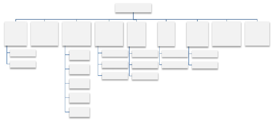
Figure 3-1. End user taxonomy decomposition.
End User
Proposal
Team
System Engr
Subsystem Engr
Subsystem
Analysts
System &
Subsystem
Engineering
ADCS
COMM
POWER
C&DH
etc.
Flight
Software
Developer
Integrator
V&V
Groun
d
Developer
Database
Operations
AI&T
Test Engr
Test Cndctr
Payload
Development
Test
Mission
Operations
Program
Customer

10
Table 3-1. Tb&S End Users Overview
Proposal Team: The proposal team includes system and subsystem (e.g., ADCS, FSW, I&T)
engineers who work with the Tb&S development team to validate competing concepts under
consideration as candidates for a proposal effort. These proposal users often become End Users under
categories defined below during the execution of the program.
Subsystem Analysts: This user category includes analysts responsible for defining and examining
the required performance capability during the proposal, refining it during the requirements and
design phase, verifying this capability during the test phase of the program, and supporting the
operations (including on-orbit operations, failure analysis, and anomaly resolution support).
Subsystem Analysts use Tb&S products to develop algorithms prior to releasing the algorithms to
FSW engineers.
System and Subsystem Engineers: This user category is comprised of system engineers and
subsystem engineers from a variety of subsystems (i.e., ADCS, Communications, Power, Thermal,
etc.). The System Engineers require Tb&S to validate and verify requirements. The engineers use
Tb&S to run system level tests to validate operation of the Space Vehicle such as orbit-in-the-life
tests and scenario-based testing (launch ascent, early orbit, end of life, etc.). Subsystem engineers use
simulators to validate or formally verify hardware or software interfaces from their components,
perform risk reduction activities, assist with anomaly resolution support (operational or test), and to
support many system level activities that may be tested or verified on the testbed or simulator.
Flight Software Engineers: This End User group is composed of Space Vehicle (Bus and Payload)
engineers as follows: FSW developers who use Tb&S products to test their software at the unit level
in an environment designed to provide realistic timing and inputs for low-level software components;
FSW integrators, who use Tb&S products to integrate software units into top level FSW end items in
End User Description
Proposal Team
Technical proposal staff developing candidate concepts during
the pre-Award phase
Subsystem Analysts
Subsystem engineers responsible for concept development and
algorithm development.
System & Subsystem Engineers
System and subsystem engineers responsible for analysis,
design and performance of space vehicle systems and
subsystems.
Flight Software Engineers
Engineers responsible for developing, integrating and testing,
qualifying and operating FSW. This category includes both
spacecraft bus and spacecraft payload flight software.
Ground Development & Operations
Engineers supporting ground and test functions including C&T
database development, ground control hardware and software.
Assembly, Integration, & Test
Test engineers and test conductors responsible for integrating,
testing, and configuring the space vehicle prior to launch.
Payload Development & Test
Payload designers, test engineers and test conductors
responsible for design and test of the space vehicle payload.
Mission Operations
Operations engineers responsible for controlling the space
vehicle after launch.
Program Customer
End customer who may be performing IV&V, training, or
integration with other parts of the larger system.
11
an environment having realistic timing and hardware interfaces to external components; FSW I&T
team, which perform dry run testing and debug activities as needed to ensure that FSW is ready for
qualification testing; and the FSW V&V team (such as the Software Item Qualification Test (SIQT)
team), who use Tb&S products to formally test FSW in an environment designed to provide a realistic
flight environment. Activities continue through and beyond launch to include regression testing, FSW
upload and patch testing, and anomaly resolution support.
Ground Development and Operations: The ground development and operations user category
consists of ground systems, Ground Support Equipment (GSE), ground software and ground database
developers. The database developers are responsible for creating and maintaining the Command and
Telemetry database. These engineers use Tb&S to test the command and telemetry database in an
environment that provides realistic telemetry responses to commands. Ground operators are
responsible for Operations & Maintenance O&M of the entire ground segment and may use Tb&S to
assist in their duties.
Payload Development and Test: This user group is a subset of the Systems and Subsystem
Engineers (described above) specifically assigned to design, build, test, and verify space vehicle
payload(s) and/or instrument(s).
Assembly, Integration and Test Team (AI&T): The AI&T team is comprised of test engineers and
test conductors. These test personnel use Tb&S to perform initial HW integration validation (risk
reduction), dry-run test procedures, investigate test anomalies, perform system-level requirements
verification, execute day-in-the-life testing, support ground station end-to-end testing, or to support
mission rehearsals.
Mission Operators: This user category includes the System Engineers and operators who comprise
the Flight Operations Support Team. These personnel conduct operations against Tb&S for mission
rehearsals and operator training activities.
Program Customer: The program customers are the End Users who may be performing V&V,
training, integration with other parts of the larger system, anomaly resolution, or FSW patch testing
and verification.
3.2 Tb&S End Use Taxonomy
The section details End Uses of Tb&S in space vehicle development and operations programs. An
End Use is defined as the application for which the end product has been designed. Within this
section, each End Use is described along with value to the program and End User. Any risks of
omitting or curtailing the End Use during a development program are discussed for each End Use.
While each End Use can correspond to a particular End User category, we do not make a direct
correlation in our description of the End Uses. We recognize the fact that each program is different
and specific correlations will vary between programs. Sample correlations of these End Uses applied
within the phases in a risk-constrained program and a resource-constrained program lifecycles are
discussed Section 4. As shown in
Figure 3-2, we define five primary End Use categories spanning
the lifecycle of Tb&S products from Concept Development to Mission Operations.

12
Figure 3-2. End Use Taxonomy Decomposition
The End Uses identified in Figure 3-2 are summarized below in Table 3-2 followed by a detailed
description of each End Use in the following sections and paragraphs.
Table 3-2. Tb&S End Uses Overview
End Use Type of End Use Description
Concept
Development
(Section 3.2.1)
Concept Studies and
Development
Proposal support: design comparisons, design
refinement, trade studies
Subsystem Algorithm
Development
Algorithm development leading to
implementation in software
FSW Development
(Section 3.2.2)
FSW Unit Test
Low-level SW component testing in a
representative environment.
FSW Development &
Software Item (SI)
Integration
Integration of SW units into a FSW builds,
including limited functional testing and
benchmarking HW requirements.
FSW Test Development
Dry running FSW qualification and verification
test scripts.
FSW Formal Requirements
Verification /Software Item
Qualification Test (SIQT)
Formal execution of FSW qualification tests to
verify FSW requirements, FSW interfaces, and
validate FSW algorithms
End Use
Concept
Development
Concept Studies
Algorithm
Development
Flight
Software
Development
Unit Test
Development &
Integration
Test Development
Verification Test
Regression Test
Integration and
Test
Test Conductor
Training
Test Procedure
Development
AI&T Risk
Reduction Test
Test Anomaly
Resolution
System Test
Cmd/Tlm DB I&T
System/Subsystem
Rqmt Verification
System/Subsystem
Validation
Fault Management
Test
Day-in-the-Life Test
Mission
Operations
Ground
Compatibility Test
Mission Rehearsals
Flight Operations
Trainging
Post-Launch
Anomaly Resolution

13
End Use Type of End Use Description
FSW Regression Test
Regression testing involves the retesting of a
software item following the modification of that
item or any of its interfacing items.
System/Subsystem
Test
(Section 3.2.3)
Command and Telemetry
Database Integration & Test
Development and testing of the flight command
and telemetry database.
System/Subsystem
Requirements Verification
Verify system/subsystem requirements and
interfaces.
System/Subsystem
Validation
Validation of system/subsystem intended use.
Fault Management System
Test
Fault detection and response testing, often
including fault injection.
Day-In-The-Life Test
Long duration and mission scenario ConOps
V&V testing.
AI&T Support
(Section 3.2.4)
Test Conductor Training
Training activities for test engineers and test
conductors.
Test Procedure
Development
Dry running AI&T test procedures prior to
running against the flight vehicle
AI&T Risk Reduction Test
Integrating or testing space vehicle systems,
subsystems, components and EMs on a testbed
prior to use on flight vehicle.
Test Anomaly Resolution
Investigations of anomalies using a Tb&S
product.
Mission Operations
Support
(Section 3.2.5)
Ground Compatibility Test
Closed loop testing to exercise ground C&T
hardware and software as well as activity
planning software.
Mission Rehearsals
Closed loop testing to exercise operations
teams, procedures and contingency flow
processes.
Flight Operations Training
Training exercises to familiarize individual
operations team members with the use of
flight/ground systems.
Post-Launch Anomaly
Resolution
Contingency activity to investigate on-orbit
anomalies on a testbed.
3.2.1 Concept Development End Uses
Concept Studies and Development: For concept studies, the Proposal team may explore operational
capabilities of the candidate designs in support of the selection of a design path that will be developed
for the proposal. In other uses, the proposal team may use Tb&S products to refine the proposal
concept. Typical studies would include design comparisons in maneuverability, controllability,
stability or line of sight, or design refinements to FSW and ADCS parameters and algorithms. The
intent of this “use category” is to ensure that data is available for trade studies used by the proposal
team in selecting the basic design concept that will be presented in the team’s proposal. The risk in
omitting or curtailing these investigations is that the proposal team risks committing to a poor design
path. This may incur added costs if earlier work has to be discarded in a fundamental design change
later in the program or if the chosen design path turns out to be more difficult than the proposal bid
originally envisioned.

14
Subsystem Algorithm Development: The purpose of the subsystem algorithm development End Use
is for subsystem engineers to finalize algorithms and parameters in preparation for delivering these
algorithms to the FSW development team. In this use, Subsystem engineers, like ACS or EPS
developers, use Tb&S to validate and debug their algorithms before delivery to FSW. Typically, the
ACS development team uses a high-fidelity analysis simulation to prove their algorithms, which is
also used to develop open-loop test cases for FSW ACS algorithm verification. The real-world
dynamics, environment, disturbance, and hardware models developed for the Tb&S products during
this End Use are often (or have the opportunity to be) re-used during later phases of the program. The
analyst dynamics test results provide truth data to be used by the Tb&S development team during
their dynamics simulator post-test analysis. The intent of this “use category” is to ensure that mature
algorithms are passed to FSW. The risk in omitting or curtailing this development work is that
inadequate algorithms may be implemented in FSW, and the need for further refinements may not
become apparent until later, more costly phases of the program, such as I&T.
3.2.2 Flight Software Development End Uses
Flight Software Unit Test: The FSW development team uses the native development environment
for SW unit test and debugging activities including boundary, coverage, and logic paths verification.
FSW developers use Tb&S to test FSW components at a unit and component level using inputs and
evaluating outputs through flight interfaces. The intent of this “use category” is to ensure that any
logical flaws or software design errors at the software component level are caught early. Using a
processor that is not exactly flight-like for the FSW unit level testing allows FSW developers to add
waypoints and other SW test hooks that the flight processors do not always support. The risk in
omitting or curtailing this testing is that errors may not be found until more costly phases of the
program and that additional expensive regression testing may be required.
Guideline 01: Ensure that the FSW unit test is performed on a Tb&S product with a realistic
FSW environment (but not necessarily on a processor targeted to be used in flight) providing
realistic component inputs and interfaces.
Rationale and Example. A worst-case risk scenario that may result from performing FSW unit
testing on a platform that is not realistic to the actual operational FSW environment would be
one in which the error is not detected at higher levels of testing because all of the component
level logical paths are not exercised.
Flight Software Development and Software Item (SI) Integration: The FSW development and
integration team uses a Tb&S product with flight-like processors to integrate software components
and to test the integrated FSW product in pre-qualification tests. Activities include performance and
stress testing of FSW, timing investigations, debug activities, and burn-down of the Discrepancy
Reports (DRs) against FSW. The intent of this “use category” is to capture and fix any issues with the
integrated FSW prior to the start of qualification testing. The risk in omitting or curtailing this activity
is one of both schedule and cost impacts resulting from failed portions of the qualification test and
having to reintegrate and retest FSW.
FSW Test Development: In this use, the team performing Software Item verification leading to SI
Qualification Test (SIQT)) uses Tb&S products to iterate through development and debug of
verification test scenarios. The intent of this “use category” is to capture and resolve defects with the
qualification test scripts prior to the start of formal qualification testing. The risk in omitting or
curtailing this activity is one of schedule impacts resulting from time spent troubleshooting test
scripts during the qualification test.

15
Flight Software Formal Requirements Verification (SIQT): The FSW formal verification team
uses a Tb&S product with Flight-Like hardware to run Qualification/Verification tests. The intent of
this “use category” is to verify the software requirements levied on FSW. Software qualification
testing may not be skipped and the risk in minimizing this activity is one of schedule impacts
resulting from time spent troubleshooting FSW in AI&T, or in a worst case, of launching a Space
Vehicle with flaws in FSW.
Guideline 02: Use Flight-Like hardware and configuration as often and as early as possible to
verify system requirements (including interfaces) during software-
item qualification testing
(SIQT).
Rationale and Example: When selling-off lower-level requirements, the use of Flight-Like
hardware in a flight configuration will allow for problems to be addressed early in the HW
development process rather than late during AI&T. In particular, adequate H/W-S/W debug
and dry run enhances the buy-off of lower-level requirements and allows for finding defects
early, and retiring of schedule and H/W-S/W risks. From the perspective of flight software, this
means that SIQT must be performed with proper flight-like hardware or EDUs to ensure that
software works as expected before AI&T.
Flight Software Regression Test: Regression testing involves the retesting of a software item
following the modification of that item or any of its interfacing items. This may include modification
to the software’s requirements, design, code, interfaces, and documentation. The regression test team
uses various Tb&S products to support this activity post-SIQT through launch and completion of the
mission.
3.2.3 System/Subsystem Test End Uses
Command & Telemetry (C&T) Database Integration and Test: The database system integration
team uses a simulator or a testbed together with a ground system interface for Command and
Telemetry database verification. Typical test activities include sending commands to the simulator or
testbed, verifying command acceptance, and verifying expected telemetry responses. These activities
do not generally require a closed loop orbit/dynamics simulation. The intent of this “use category” is
to ensure that the database in use at the start of spacecraft bus integration is valid.
Guideline 03: Use a Tb&S product executing Flight Software to verify Flight Commands and
Telemetry.
Rationale and Example. As the FSW goes through various levels of testing and evolution the
changes have to be propaga
ted to other parts of the system including the command and
telemetry database. The risk of omitting or curtailing this activity is that database errors found
during Space Vehicle integration may cause anomalies that impede rapid progress through
integration and test. In addition, programs that omit this use must evaluate which commands
and telemetry have been exercised during AI&T in order to pass the final program gates prior
to launch.
System/Subsystem Requirements Verification: The program test team uses a Tb&S product with
Flight-Like hardware to run verification tests. This includes closed loop orbit scenario tests for formal
verification of system level requirements and other tests requiring dynamics modeling of the external
environment. Typical activities include: ADCS performance testing; fault protection tests of flight

16
hardware systems that require closed loop dynamics or fault injection; Day-In-The-Life tests; and
launch simulation tests. For subsystem testing, it is important that all the other subsystems are up and
running in their nominal configuration in order to observe subsystem interaction for any design
impacts. The intent of this “use category” is to provide the highest fidelity hardware environment
(outside of the flight vehicle) for verification of requirements that cannot be verified outside of the
testing of final flight hardware configurations. Verifications may not be skipped; however,
minimizing testing of these requirements in Tb&S results in added costs associated with the higher
level space vehicle tests that would have to replace this testing. Programs with the resources to
develop offline simulators and testbeds of the fidelity required to shift these activities off of the space
vehicle may be able to minimize or eliminate tests using the space vehicle in closed loop tests from
their program timeline.
System/Subsystem Validation: The program test team uses a Tb&S product with flight-equivalent
hardware to execute a set of validation tests necessary to demonstrate that the as-built system
performs its intended functions (i.e., complies with the documented needs of the stakeholders) in its
intended environment. Although most validation is accomplished through simulation and analysis,
Tb&S provides an opportunity to perform selected validation using test. Certain testing, like Test
Like You Fly (TLYF) can be considered a validation test using Tb&S.
Fault Management System (FMS) Test: Testing of the Space Vehicle fault management system
needs to occur for the autonomous on-board fault detection and recovery capabilities implemented in
the FSW as well as for the higher-level detection and responses allocated to the Space Vehicle and
Ground System. The FMS testing End Use assumes that the developers have the final FSW and that
lower level subsystem level tests were successful and complete. Testing includes the validation of all
the on-board response and recovery stored command sequences and timing. Testing may use modeled
components that can more easily inject test faults (e.g., out-of-range temperatures). Because FMS
testing requires use of integrated flight systems, it occurs later in the program lifecycle, and it incurs
greater program costs and schedule impacts. Programs may use the flight vehicle augmented with
testbed components for fault management testing and combine it with fault protection testing using
testbeds or simulators. The intent of this “use category” is to ensure that system level requirements in
fault management are verified.
Guideline 04: Perform as much Fault Management testing on the System Testbed as possible.
Rationale and Example: The STB provides greater capability to inject realistic faults,
providing greater fidelity and robustness for most type of fault testing. This type of testing
should augment tests performed on the space vehicle flight hardware. The risk in omitting or
curtailing this activity is that Fault management essential to the safety of the Space Vehicle
may contain design or implementation errors that effect on orbit performance and Space
Vehicle safety.

17
Guideline 05: Ensure that at least one Tb&S product can incorporate the required capabilities
associated with fault injection and fault detection, with sufficient flexibility available for
injecting faults in different ways. This includes not only SW fault injections but also HW/SW
timing faults and HW fault injection.
Rationale and Example: One of the most critical capabilities associated with how a Tb&S
product incorporates fault-injection is the ability to inject faults while numerous flight tasks are
being performed in parallel across all space vehicle processors. Often, during AI&T,
commands to exercise the response of each item in the space vehicle are sent in some logical
order, which does not reflect the actual operational environment when faults occur during the
execution of any given command. A fault may occur at any time during the mission with any
number of tasks executing in parallel.
Day-In-The-Life (DITL) Test: In this use a Tb&S product is employed to run mission scenario tests.
Typical activities include examinations of sensing/maneuvering CONOPS or ground station
interactions in a closed loop orbit scenario. These are typically long duration tests (several hours),
intended to exercise the SV subsystems and FSW through a complete cycle as outlined in the
CONOPS document. Testing is generally looking for incompatibilities between different operational
activities, or for software/processor issues that are either infrequent or require long gestation periods.
Testing is also looking for SW/HW issues that are dependent on command sequencing (e.g.,
forgetting to clear buffers prior to next command). The DITL End Use also includes using a testbed
or simulator for executing expected operations sequences that is out of the flow of the more expensive
AI&T activities. The intent of this “use category” is to ensure that mission scenarios will properly
execute on-orbit. The risk of omitting or curtailing this activity is that conflicts between operational
activities may not be detected until the Space Vehicle is on orbit, and the time spent reworking
operational scenarios detracts from mission success. In a worse case risk outcome, the on-orbit Space
Vehicle may be found to include processor or software issues that cause resets or other loss of
function at intervals greater than that tested in all other ground testing. The risk of omitting this
activity on a System Testbed and deferring testing to the space vehicle is one of schedule and cost
risks, but these risks may be balanced by the benefits of testing the final flight configuration instead
the System Testbed configuration.
3.2.4 AI&T Support End Uses
Test Conductor Training: The AI&T Team uses a Tb&S product to develop competencies with the
command and telemetry interface, with the Space Vehicle architecture, and with the simulator
software. A wide range of activities, from running simple open loop hardware setup operations to
running closed loop orbit simulations, are exercised using these Tb&S products. The intent of this
“use category” is to provide test conductors an enhanced competency in some of the more technically
challenging portions of the test environment prior to the start of flight Space Vehicle AI&T
operations. The risk in omitting or curtailing these activities is that subtle test issues encountered in
AI&T may be missed or misunderstood by test operators, in a worst case leaving these issues
undetected until the Space Vehicle is on orbit.
Test Procedure Development: The Assembly, Integration & Test Team uses a simulator or a testbed
to dry run I&T procedures. I&T procedures may be broadly classified as either integration procedures
or test procedures. Each classification has different Tb&S needs. Integration procedures are dry run
18
to verify the safety and the validity of the steps used to verify correct and safe electrical interfaces in
the flight hardware. Dry runs of this type of procedure require that the simulator has realistic
electrical hardware and interfaces at the point that the procedure is executed. Test procedures, on the
other hand, are more typically focused on checking the function and performance of integrated
systems and subsystems. For this type of dry run, simulators usually only need to realistically respond
to commands in the same manner as the flight hardware, and in many cases the relevant spacecraft
components may be entirely simulated. The intent of this “use category” is to ensure that the different
types of test procedures used in AI&T activities function safely and as expected prior to execution
against flight hardware. The risk in omitting or curtailing this activity is two-fold. First, for
integration tests, this activity reduces the risk of hardware damage due to incorrect manipulations and
excitations of flight hardware. Second, in system-level tests, this activity reduces the added cost and
schedule impacts of troubleshooting complicated orbit scenarios or system level behaviors during the
more expensive space vehicle AI&T activities.
AI&T Risk Reduction Test: AI&T, subsystem or system engineers require a testbed with an EM or
flight components to perform interface verification, initial requirement validation, and pre-integration
checkout necessary to reduce the risk associated with initial flight vehicle power-up activities as well
as follow-on AI&T activities. The intent of this “use category” is to ensure proper operation of
hardware, flight software, ground equipment, or test equipment prior to installation and use on the
flight vehicle. The start point for this End Use is the availability of appropriate EM units (or Software
components) for testing and generally extends to beginning of system level AI&T.
Test Anomaly Resolution: The AI&T Team or systems and subsystem engineers use a testbed to
recreate and examine anomalies found in the execution of test procedures during space vehicle AI&T
activities. Typical activities include investigations of ACS attitude errors, unexpected fault detection
triggers, signal timing issues, and unexpected HW or SW responses and failures. The intent of this
“use category” is to provide a path for troubleshooting that is offline to more expensive AI&T
activities. By their nature, these activities are not planned ahead and every program hopes that they
will not have to utilize this capability. Nevertheless, planning for these contingency operations is
important to smooth program execution and is a logical extension of the capabilities required for the
previous “use category”. The ability to quickly interrupt other activities to allow for time on the
testbed resource is crucial in maintaining the flow and schedule of AI&T. This is due to the fact that
failures on the space vehicle are often desired to be fully understood before any testing may continue
(or even powering off the space vehicle), thereby preventing unverified failures. Tb&S have a crucial
role in providing this understanding. The risk in omitting or curtailing this function is twofold. First,
this activity reduces the risk of hardware damage by reducing the quantity of troubleshooting with
flight hardware. Second, this activity reduces the added cost and schedule impacts of troubleshooting
complicated orbit scenarios during the more expensive space vehicle AI&T activities.
3.2.5 Mission Operations Support End Uses
Ground Compatibility Test: The Mission Operations Team uses Tb&S products to run orbit
scenarios in support of end-to-end testing of ground station command center(s). Activities may
include mission scenario tests in closed loop orbit simulations. The intent of this “use category” is to
exercise the ground controller’s command and telemetry interfaces and their activity and planning
software. The risk in omitting or curtailing these activities is that issues with ground station hardware
and software may not be detected until the Space Vehicle is on orbit, and the time spent reworking
these resources detracts from mission success.

19
Mission Rehearsals: The Mission Operations Team runs closed loop orbit simulations in support of
operational scenarios run by operations personnel at the ground station command center(s) using
Tb&S. Activities include mission scenario tests in closed loop orbit simulations, in both nominal and
anomalous configurations. The intent of this “use category” is to exercise the ground staff, their
decision-making process, procedures and their procedure flows, in a variety of nominal and off-
nominal activities that represent all possible on-orbit conditions. The risk in omitting or curtailing
these activities is that issues with personnel availability, procedures and decision-making protocols
may not be detected until the Space Vehicle is on orbit, and the time spent reworking these resources
detracts from mission success.
Flight Operations Training: In this End Use the Mission Operations Team uses a simulator or
testbed to develop competencies with their command and telemetry interface and with the Space
Vehicle architecture outside of full mission rehearsals. A wide range of activities from running simple
open loop hardware setup operations to running operations in closed loop orbit simulations are
executed. The intent of this “use category” is to provide operations personnel with additional
experience in controlling and working with their ground systems in response to Space Vehicle
operational scenarios. The risk in omitting or curtailing these activities is that operators may be less
skillful in using the ground systems to respond to issues on orbit causing unnecessary schedule delays
in on orbit activities.
Post-Launch Anomaly Resolution: In this use Mission Operations Team with the help of
systems/subsystems engineers (including FSW engineers) use a testbed to recreate and examine
anomalies found in on-orbit operations. The intent of this “use category” is to provide a means for
troubleshooting that allows access to hardware that is otherwise out of reach. In addition, it allows
some types of troubleshooting to take place in parallel with ongoing mission operations. The risk in
omitting or curtailing this activity is that any on orbit issues that arise may require more time to setup
a suitable surrogate test environment or that testing is done on the space vehicle with much greater
risk.
3.3 Tb&S Functional Taxonomy
This section lists a set of common functional capabilities required of the suite of Tb&S associated
with space vehicle development and operations programs. These functional capabilities are
implemented in direct response to End Uses identified in Section 3.2. As in the previous section, this
section does not make a direct correlation in the description of the functional capabilities to specific
End Uses since each program is different and specific correlations will vary between programs (see
Section 4 for a typical allocation to a risk-constrained program). Table 3-3 provides a list of functions
and while it is not comprehensive, it is representative of the types of functions seen in Tb&S products
used throughout the Aerospace industry.
Table 3-3. Top-Level Functions Provided by Tb&S Products
Top-Level Function Summary Description
Process Space Vehicle Uplink
Commands
Testbed provides uplink of flight commands from operator
workstation.
Provide Space Vehicle Downlink
Telemetry
Testbed provides downlink of flight telemetry to operator
workstation.
Run Simulation non real-time
Testbed simulation SW may run faster or slower than real-time.

20
Run Simulation in real-time
Testbed simulation SW runs in real-time.
Simulate Space Vehicle Components
Testbed includes software models of one or more flight
components.
Include Hardware EMs
Testbed includes flight or non-flight hardware units of one or
more flight components, and a RTOS to control SW interfaces
to hardware components.
Simulate Space Vehicle Orbital
Dynamics
SW models include integration of force/acceleration, velocity
and position of the simulated vehicle.
Simulate Space Vehicle Attitude
Dynamics
SW models include integration of torque/angular acceleration,
rotations and attitude of the simulated vehicle.
Provide Interfaces to C&DH
Subsystem Hardware
Testbed includes C&DH hardware, and all interfaces to this
hardware are either simulated or emulated.
Provide Interfaces to FSW
Testbed includes FSW, and all interfaces to FSW are either
simulated or emulated.
Provide for Test Planning,
Execution, and Post-Test Analysis
Operator interface on testbed includes tools for storage,
manipulation and analysis of testbed data.
Provide interface to EM Hardware
Testbed includes physical signal lines with realistic signals at
all interfaces for specific test articles.
Provide interface to external EGSE
Testbed provides test interfaces to EGSE including power or
test boxes.
Provide interface to external C&C
Testbed includes capacity to select command/telemetry streams
from both local and remote operators.
Provide realistic hardware
redundancy
Testbed includes both primary and redundant hardware for at
least some boxes in some subsystems.
3.4 Tb&S Physical Taxonomy
In this subsection, we take the Tb&S End Users, End Uses, and functional capabilities discussed in
Sections 3.1, 3.2, and 3.3 and identify specific Tb&S products that are applicable to space vehicle
programs across the Aerospace industry. Depending on the program constraints (i.e., schedule, risk,
and cost) the actual uses for each Tb&S type may vary or may not be used at all. What we describe in
this section is not a specific allocation of Tb&S products for a particular space vehicle program (see
Section 4), but rather a general physical characterization of Tb&S products into four main Tb&S
types applicable to all space vehicle programs. The four Tb&S products we consider are as follows:
Section 3.4.2.1: Non-Real-Time Simulator (NRT-Sim)
Section 3.4.2.2: Non-Flight-Like Testbed (NFTB)
Section 3.4.2.3: System/Subsystem Testbed (STB)
Section 3.4.2.4: Integrated Space Vehicle Testbed (ISVT)
A functional decomposition of a space vehicle system testbed is presented followed by a detailed
discussion of each of the four Tb&S types. The functional overview provides a high-level illustration
of the functional relationship between the Engineering Model (EM) hardware, interface hardware,
simulated SV dynamics and environment models within a Tb&S product.

21
3.4.1 Space Vehicle System Testbed Product Decomposition
The decomposition of a generic Tb&S product is illustrated using several hierarchical tiers. Each
successive tier corresponds to a functional decomposition of the Testbeds components from the
previous tier. Figure 3-3 shows the first tier (top-level) decomposition of the testbed into four
components. The testbed is shown to contain flight-like Engineering Models and Testbed Simulators.
The SV Testbed also contains support equipment (i.e., EGSE) and has an Operator Console
representing the Ground Command & Control system as well as a Test Conductor console necessary
to execute tests.
Figure 3-3. First tier decomposition – space vehicle system testbed.
The Dynamics Simulator, shown in Figure 3-4 is comprised of simulations of flight components,
hosted on a workstation, running a non real-time or real-time operating system. The simulator
includes an operator interface used to start, stop, and configure the dynamics simulator before and
during tests. This simulator type is used to provide the either open-loop or closed-loop control
capability. This simulator type may also be used to interface to a non-flight-like processor hosting
FSW. The Dynamics Simulator consists of six components, including: the Simulator Hardware
Platform, which hosts the Simulator Operating System and the computing platform for executing
simulator software; the Simulation Framework component, which is a software component used to
support Space Vehicle subsystems and components models as well as the Space Environment
Models; the Space Vehicle Models component, which consists of software items representing
component behavior, interfaces, and timing characteristics; and the Environment Models, which are
software representations of real-world space environments such as atmospheric drag.
Figure 3-4. Second tier decomposition - dynamics simulator.

22
At a high level, two distinct types of dynamics simulators are typically developed; Bus Dynamics
Simulators and Payload Dynamics Simulators. A Bus Dynamics Simulator is designed to provide
simulation of bus flight hardware components and the Space Vehicle environments as well as
interfaces to the Space Vehicle’s payload(s) and/or instruments. The UUT for a Bus Dynamics
Simulator is the set of Bus EMs. Payload Dynamics Simulators are designed to provide simulation of
flight hardware components critical to the payload as well as any Space Vehicle environments that
impact the payload and/or instrument. The UUT for a Payload Dynamics Simulator is the flight
payload or the payload EM.
The Space Vehicle Model decomposition, shown in Figure 3-5, is comprised of Spacecraft Bus
Models and the Payload Models. These models are software representing component behavior,
interfaces, and timing characteristics. The Environmental Model decomposition, shown in Figure 3-6,
is comprised of the forces, torques, and other environmental effects on the vehicle dynamics and
sensors. The models are software representations of something in the real-word.
Figure 3-5. Third tier decomposition - space vehicle models.
23
Figure 3-6. Third tier decomposition - environmental models.
All four Tb&S product types, identified here, are composed of a subset of the individual components
of the Space Vehicle System Testbed shown above. The differences from one type of testbed or
simulator to another lie in the level of fidelity in the implementation of each SV component or
subsystem and in how close each simulated or hardware component is to the actual flight
configuration.
3.4.2 Tb&S Types and Physical Characteristics
For each Tb&S type we describe its characteristics, assumptions, limitations, and End Uses. These
systems vary in terms of their performance and fidelity requirements. The high-performance/high-
fidelity Tb&S products are required to execute flight-like scenarios, providing real-time Quality-Of-
Service while maintaining stringent timing requirements. These types of Tb&S products also tend to
be the most complex and expensive systems to develop and use. The level of fidelity for a Tb&S
product could be viewed at two different levels. At the system level, it represents the level of
hardware-in-the-loop (HITL) in the configuration of the testbed, while at the modeling level for
simulated components it represents the accuracy and precision of the model outputs. Some Tb&S
products are designed to maintain real-time performance at lower rates while providing math-
intensive operations with high precision model outputs. Others are designed to run at higher rates
with lower fidelity model outputs. As noted in Section 6, some Tb&S products typically evolve and
improve during the course of the program and therefore separate capabilities of Tb&S products of
different levels of maturity are used during various phases of the space vehicle development program.
It is expected that in multiple-build SV programs, or programs with a high level of commonality in
the designs of consecutive satellites, that the Tb&S product will be at a higher level of maturity than
for “one-off” space vehicle builds. When a more mature Tb&S type is available, the End Uses for the
more primitive level of Tb&S type listed below may be passed to a higher-fidelity tool.

24
In our description of each Tb&S product type, we address the notion of the fidelity level required
(from the user’s perspective) for three aspects relating to Tb&S products: Interface Fidelity,
Hardware Fidelity, and Simulation Software Fidelity.
Guideline 06: Identify the fidelity levels required for each Tb&S product capability early in
the lifecycle.
Rationale and Example: Fidelity levels for hardware, interfaces, and simulation software
models provide the functional and performance capability to satisfy identified End Uses. The
fidelity level may significantly drive scope (and therefore cost and schedule) of the end product
and may cause significant rework if identified late in the development or operations lifecycle.
Interface fidelity levels (see Table 3-4) describe how closely the interface associated with the
simulator or testbed matches the actual flight interface. They vary from physical interfaces over
electrical connections between actual hardware components to non-physical interfaces used to support
simulator and testbeds. Hardware fidelity levels (see Table 3-5) describe how closely the simulator or
testbed hardware matches the actual flight vehicle hardware. Finally, simulation software model
fidelity levels (see Table 3-6) describe how closely the dynamics simulator on testbed hardware
matches the actual flight vehicle. Simulation software models are developed and deployed on every
Tb&S product type as part of the Dynamics Simulator, shown in Figure 3-4. Some simulation
software is used to model various physical and non-physical parts of the space system, space vehicle,
and the environment in which it operates. Detailed description of the simulation models, including
description of the set of attributes having either a qualitative or quantitative description that can be
used to specify the level of detail or complexity of a given model is beyond the scope of this
document.
Table 3-4. Tb&S Interface Fidelity Levels
Interface
Fidelity Level (0-5)
Summary Description
(0) No Interface capability
No interface is provided between two end items
(1) Software Interfaces
Shared memory or other method to connect to systems/components
together using software rather than electrical representation of the
interface
(2) Simulated Interfaces
An interface is provided that adequately represents the data and
general temporal characteristics of the interface
(3) Non Flight-Like Electrical Interface
A commercial equivalent emulation of the flight electrical interface
(4) Flight-Like Electrical Interface
An equivalent electrical interface, but not using flight qualified parts
and cables
(5) Flight Electrical Interface
Actual flight electrical interface exists between end items

25
Table 3-5. Tb&S Hardware Fidelity Levels
Hardware
Fidelity Levels (0-4)
Summary Description
(0) No Hardware capability
No hardware capability is provided
(1) Non flight-like Hardware
Commercial hardware capability that has no direct correlation to the
flight hardware
(2) Emulated Hardware
Typically a commercial equivalent that has different performance
(3) Flight-Like Hardware
Usually described as an EM present in a testbed. Typically uses non
radiation-hardened parts, but has similar performance to the flight
hardware present in a testbed or simulator.
(4) Flight Hardware
Flight hardware present in the testbed
Table 3-6. Tb&S Simulator Software Model Fidelity Levels
Simulator Software Model
Fidelity Levels (0-3)
Summary Description
(0) No Simulation Software
capability
No simulation software model capability is provided
(1) Simple Model
A static representation (e.g. fixed data) of the output of the end item being
modeled
(2) Simple Dynamics Model
A simple dynamics model representing input and output of the end item
being modeled. This model’s input and output data changes during
execution, including simple responses to input parameters.
(3) Dynamics Model
A more complex dynamics model representing all required input and output
data of the end item being modeled. Dynamics behavior is modeled
(usually with algorithms) with ties to other models and the surrounding
environment.
3.4.2.1 Non-Real-Time Simulator
A Non-Real-Time Simulator (NRT-Sim) is a purely software simulation, hosted on a workstation,
that when implemented includes a command and telemetry interface to both the simulation software
and to the hosted flight software. This simulation does not include flight or EM hardware in the loop.
At a mature level it typically includes fully integrated FSW, which might be flight qualified as well.
An illustration of a typical NRT-Sim example is depicted in Figure 3-7. An NRT-Sim configuration
can include a fully integrated FSW or one of the simulation models may be a model of the FSW that
can be used as a C&T simulator. Interface fidelity for an NRT-Sim is low and can be anywhere from
a level 0 (No Interface Capability) to a level 1 (Software Interfaces). The hardware fidelity level is
almost always at level 0: No Hardware Capability. The simulator software model fidelity, however,
can vary from level 1 (Simple Model) used for faster-than-real-time Mission Rehearsals and Ground
Operations End-to-End Tests to very high-fidelity level 3 (Dynamics Model) that has too much
fidelity to operate in a time-constrained environment such as a real-time dynamics simulator, but may
be required to support activities associated with access to all aspects of the end item being modeled.

26
Figure 3-7. Context diagram - non-real-time simulator example.
Generally, NRT-Sims are relatively inexpensive platforms for early flight SW development without
HTIL. NRT-Sims are good tools for benchmarking HW requirements for FSW, refining procedure
and test script event timing and contents, modeling of Space Vehicle dynamics response to command
sequences. They also may be used to provide a realistic interface to the Space Vehicle ground system
for C&T database verification to enable early database development without HITL and for use as an
Operator training device. Some of the weaknesses of an NRT-Sim include: lack of real-time
performance for internal/external interfaces; lack of event-driven flight-like scenario execution and
testing; lack of hardware dependent constraints on SW functions; and models of vehicle hardware
may have limited scope and capability.
3.4.2.2 Non Flight-Like Testbed
A Non Flight-Like Testbed (NFTB) has the capability to operate as a subsystem or system testbed but
uses lower fidelity hardware. It contains a dynamics simulator that can support either simple open-
loop or dynamics closed-loop capabilities. The dynamics simulator can execute either non real-time
or real-time depending on the required capability. The testbed contains non flight-like units hosting
the FSW under test in order to verify the on-board FSW. The testbed includes an open-loop emulation
of the flight interfaces and may include the dynamics models necessary for closed loop testing. The
testbed also provides a command and telemetry interface to the operator.
An NFTB having a real-time FSW simulator and a real-time dynamics simulator is depicted in Figure
3-8 below. The different fidelity levels for an NFTB are higher than those for an NRT-Sim. Interface
fidelity can range from level 3 (Non Flight-Like Electrical Interface) all the way to level 4 (Flight-
Like Electrical Interface). Similarly, hardware fidelity levels range from level 1 (Non flight-like
Hardware) to level 2 (Emulated Hardware) using a commercial equivalent to the flight hardware.
Since the uses of an NFTB are not too different from those for an NRT-Sim, the software simulation
models’ fidelity levels can be anywhere between level 2 (Simple Model) to a high-fidelity level 3
(Dynamics Model).

27
Figure 3-8. Context diagram - non flight-like testbed example.
In cases where an NFTB runs the actual FSW on a hardware platform resembling an emulation of the
flight processor, an NFTB may provide a simpler means than an NRT-Sim for porting FSW to a test
environment. This Tb&S type may have some limitations, including the lack of event-driven flight-
like scenario execution and testing, and limited scope and capabilities of the SV hardware models and
host hardware for FSW.
3.4.2.3 System and Subsystem Testbed
A System/Subsystem Testbed (STB) is a combination of Engineering Models (EMs) and/or flight
boxes, coupled with a Dynamics Simulator in a Hardware-in-the-Loop (HITL) configuration, which
simulates some flight components and also includes the orbital and attitude dynamics models.
Subsystem Testbeds may be configured to represent a subsystem such as FSW, EPS, and C&DH.
System Testbeds are commonly configured as:
• Space Vehicle Testbed
• Bus System Testbed
• Payload System Testbed
A generic representation of a Subsystem Testbed configuration representing a FSW Subsystem
Testbed (i.e., FSW Test Bench) is depicted in Figure 3-9 below. A full System Testbed is illustrated
in Figure 3-10, where at a minimum, flight or EM boxes represent most of the C&DH flight
components. The hardware fidelity levels range from level 3 (Flight-Like Hardware) all the way to
level 4 (Flight Hardware). Each STB also includes a command and telemetry interface to both the
simulation software, to the simulated flight components (if any), and to the hardware flight
components. Interfaces between simulated and hardware components require dedicated interface
hardware. Interface fidelity levels range from level 4 (Flight-Like Electrical Interface) to level 5

28
(Flight Electrical Interface). In order to interface correctly with the hardware components in the loop,
the simulation software must run in a real-time operating system (RTOS) and the software simulation
models are at the highest possible fidelity levels compatible with real-time operation: i.e., level 3
(Dynamics Model). In general, the EMs and flight boxes requiring FSW in an STB will typically
include fully integrated FSW and a command and telemetry database.
Figure 3-9. Context diagram – subsystem testbed (FSW subsystem testbed).
Figure 3-10. Context diagram – system testbed.

29
Given that an STB is of relatively high fidelity and more accurately represents a full SV or an SV
subsystem (such as FSW), an STB is a suitable high-fidelity environment for FSW and hardware
testing.
3.4.2.4 Integrated Space Vehicle Testbed (ISVT)
An Integrated Space Vehicle Testbed (ISVT) is a mating of integrated space vehicle hardware with a
Dynamics Simulator in a Hardware-in-the-Loop (HITL) configuration. This configuration is depicted
in Figure 3-11. The simulator provides the orbital and attitude dynamics models, takes spacecraft
actuator information to update the state of these models, and then feeds appropriate sensor signals to
the spacecraft. The integrated flight vehicle testbed also requires other components of the AI&T
environment, typically a suite of power EGSE/STE components and a command and telemetry
interface to both the simulation software and the Space Vehicle. In order to interface correctly with
the hardware components in the loop, the simulation software must run in a real-time operating
system (RTOS). The ISVT typically has the highest possible fidelity levels compatible with real-time
operation for interface fidelity, hardware fidelity, and software simulation models.
Figure 3-11. Context diagram - integrated space vehicle testbed.
Some of the most important characteristics that distinguish an ISVT from a high-fidelity STB are that
an ISVT is most flight-like for software or hardware testing and because of the incorporation of final
flight boxes and structures, is the only platform configured for testing that will capture issues in
workmanship or in the interaction of control systems with the dynamics of the vehicle structure.
Finally, a summary matrix of how the Functional Capabilities identified in Section 3.3 can be
allocated to the four Tb&S types described above is shown in Table 3-7 below. The Functional
allocation matrix is defined using three scales for applicability to a particular Tb&S type:

30
(F)requently, (O)ccasionally, and (R)arely. This allocation scheme represents coupling between the
functional capabilities and the physical fidelity characteristics in a particular Tb&S type that was
found to be typical among the aerospace companies canvassed in the development of this document.
Table 3-7. Top-Level Functions Mapped to Tb&S Types
Functional Allocation to Tb&S
F=Frequently, O=Occasionally, R=Rarely
Top-Level Function
NRT
Simulator
Non Flight-
Like Testbed
System/
Subsystem
Testbed
Integrated
Space
Vehicle
Testbed
Process Space Vehicle Uplink Commands O O F F
Provide Space Vehicle Downlink Telemetry F F F F
Run Simulation non real-time F O R R
Run Simulation in real-time R O F F
Simulate Space Vehicle Components F F F O
Include Hardware EMs R O F F
Simulate Space Vehicle Orbital Dynamics F F F F
Simulate Space Vehicle Attitude Dynamics F F F F
Provide Interfaces to C&DH Subsystem
Hardware
R O F F
Provide Interfaces to FSW O F F F
Provide for Test Planning, Execution, and
Post-Test Analysis
O O F F
Provide interface to EM Hardware R O F F
Provide interface to external EGSE R O F F
Provide interface to external C&C O O O O
Provide realistic hardware redundancy R O O F
31
4. Allocation of Tb&S Products within the Lifecycle Phases of an SV Program
This section describes the allocation of the Tb&S End Uses and Functional Capabilities identified in
Section 3 to the different Tb&S platforms within the lifecycle phases of typical SV programs.
Because there is no single “typical SV program” this section confronts the complexity of Tb&S
allocations for a broad range of different program types. This is done by presenting an overview of
two program types that lie at opposing ends of the spectrum, and by detailing Tb&S allocations for a
selected program type as a means of illustrating the sorts of allocation planning that all programs
must perform early in the program lifecycle.
4.1 Space Vehicle Development Program Types Overview
As described in Section 5, one of the more difficult tasks in planning the Tb&S development timeline
for any program is the determination of the program-specific constraints that will drive the
development schedule. Since each program will have a unique set of constraints, the challenge for this
document (and Section 4 in particular) is to present an overview of the “problem space” for program
level planning of Tb&S product allocations. The “problem space” is bounded by two types of
programs defined as follows:
Risk-Constrained Programs: Risk-constrained programs are those that are willing to make cost
and schedule flexible to lower risk by allocating the resources and schedule necessary to buy-
down risk items early and often.
Resource-Constrained Programs: Resource-constrained programs exhibit strict customer-
imposed delivery constraints coupled with stringent cost constraints. In this case, the
constrained resource is defined as both schedule and cost.
In between these two extremes is the range of specific individual programs that fill in the middle
ground in the problem space. It must be noted, however, that regardless of the program type, cost is
an important constraint to any program and there can be cost savings even in risk-constrained
programs if the planning of Tb&S product development and allocation is done carefully upfront. It
must also be noted that programs are not tolerant of risk to mission success, but rather each program
utilizes Tb&S resources differently to retire mission success risk at different points in the program
schedule.
4.1.1 Risk-Constrained Programs
A typical risk-constrained SV program is characterized by a willingness to provide Tb&S budget
early to reduce risk and prevent cost overruns in the back-end of a program’s development lifecycle.
Such a program may have a slower vehicle development schedule that does not easily outpace the
Tb&S development timeline. Often (but not always) a risk-constrained program is a program
composed of non-heritage or modified avionics or avionics that have not previously worked together
that require a traditional avionics development cycle before AI&T. Schedule planning for risk-
constrained programs must strive to ensure that Tb&S products are available and in use to catch
design issues early in order to lessen impacts during AI&T. For this reason, a greater proportion of
testing is assigned to System/Subsystem Testbed (STB) activities, as opposed to using the later-
developed Integrated Space Vehicle Testbed (ISVT) as shown in Figure 4-1. Sometimes in risk-
constrained programs a Tb&S product is on the program’s critical path and there is a willingness to
delay SV development schedules if Tb&S products are not delivered on time or at the required
maturity level. With proper planning, Tb&S types may be deployed to perform more than one End

32
Use; such as when the FSW Subsystem Testbed is used for FSW SIQT, regression testing for issues
found during Space Vehicle Testbed testing and FSW maintenance post launch. Proactive planning
may also streamline Tb&S deployment by assessing fidelity requirements and utilization scheduling
in order to reduce the number of Tb&S deployments. For example, if the STB fidelity is assessed to
be good enough to perform Fault Management V&V and System Verification, then the program could
choose to not implement the ISVT, even though Figure 4-1 allocates the ISVT to those particular End
Uses.
Figure 4-1. Risk-constrained - Tb&S deployment types by program phase.
4.1.2 Resource-Constrained Programs
At other end of the SV program type spectrum are resource-constrained programs. A resource-
constrained program is one where rapid progress towards a firm launch date or meeting a strict budget
mark has higher priority than an early retirement of risk. Typically, resource-constrained programs
exhibit faster and stricter vehicle development schedules, with larger portion of the budget allocated
to program activities in proportion to Tb&S activities. Resource-constrained programs may also
exhibit relatively smaller cost and schedule vulnerabilities to missteps in early vehicle design. Some
organizations consider resource-constrained programs (as defined here) as programs that are based on
mostly heritage avionics that may require less Tb&S in the development cycle. It may also be
anticipated that the aggressive risk management in this type of program is more often found in fixed-
price programs, or programs with customers who may also be under significant schedule pressure.
Regardless of how much heritage avionics is used, however, one common occurrence within
resource-constrained programs is that the high-fidelity Tb&S products will not be ready much ahead
of the integration of the flight vehicle, making the ISVT more central to the resource-constrained
program than in the risk-constrained program. A typical resource-constrained program may exhibit an
unwillingness to delay vehicle program level schedules if Tb&S products are not delivered on time or
at the required maturity level. This reduces the criticality of the program’s STBs relative to the
program’s ISVT and many of the Tb&S End Uses discussed in Section 3.2 can be performed using an
ISVT, as shown in Figure 4-2.

33
Figure 4-2. Resource-constrained - Tb&S deployment types by program phase.
4.1.3 General Tb&S Allocation to End Uses for Different Program Types
The two “limiting case” programs, discussed above, naturally allocate their Tb&S resources
differently for different End Uses. The risk-constrained program will plan for more comprehensive
System Testbeds, with higher levels of fidelity. This program will use these high fidelity testbeds to
offload significant portions of requirement verifications, risk mitigation, and other Tb&S uses from
the single stream AI&T activities later in the program lifecycle. The resource-constrained program
on the other hand, will plan for simpler System Testbeds that can be delivered faster while meeting
minimal needs (typically focused on FSW development) and will then defer many system level
verifications to closed loop testing in AI&T using the ISVT. This type of program will also typically
shift some risk management activities to less comprehensive non-simulator resources if this can be
done without compromising schedule. Regardless of the program type, however, some of the Tb&S
types identified in Section 3 will be more appropriate for some End Uses than others.
Table 4-1 is a matrix of how the Tb&S End Uses identified in Section 3.2 can be allocated to the four
Tb&S types for any type of SV program. The End Use allocation matrix is defined using three
different labels indicating if a Tb&S is appropriate for each End Use: (F)requently, (O)ccasionally,
and (R)arely. This allocation scheme is meant as an allocation that applies to any type of program,
independent of the program lifecycle phase. It is expected that a program manager responsible for
developing a plan for a program’s Tb&S products will be able to use Table 4-1 to allocate each End
Use to a particular Tb&S product and program phase as appropriate. In Section 4.3, a specific
allocation is done for a risk-constrained program, organized by program phase.

34
Table 4-1. Tb&S Uses Mapped to Tb&S Products for all SV Program Types
End Use Allocation to Tb&S
F=Frequently, O=Occasionally, R=Rarely
End Use
Category
End Use NRT-Sim NFTB STB ISVT
Concept
Development
Concept Studies and Development
O
O
R
R
Subsystem Algorithm Development
F
O
O
R
FSW
Development
FSW Unit Test
O
O
R
R
FSW Development & SI Integration
R
O
O
R
FSW Test Development
O
O
O
R
FSW Formal Requirements Verification
and Software Item Qualification Test
(SIQT)
R
R
F
O
FSW Regression Testing
R
R
F
O
System /
Subsystem Test
Command and Telemetry Database
Integration & Test
O
O
F
O
System/Subsystem Requirements
Verification
R
R
F
F
System/Subsystem Validation
R
R
F
F
Fault Management System Test
R
R
F
F
Day-In-The-Life Test
R
R
F
F
Test Conductor Training
O
O
O
O
AI&T Support
Test Procedure Development
O
R
F
O
AI&T Risk Reduction Test
R
R
F
O
Test Anomaly Resolution
R
R
F
R
Ground Compatibility Test
R
R
O
O
Mission
Operations
Support
Mission Rehearsals
O
O
F
O
Flight Operations Training
O
O
F
O
Post-Launch Anomaly Resolution
O
R
F
R
In order to illustrate a sample case of Tb&S allocations, the remaining paragraphs of this section will
first overview the different lifecycle phases (Section 4.2) and then will present the example of Tb&S
allocations on a risk-constrained program (Section 4.3). The decision to focus on only one end (risk-
constrained) of the “problem space” in Section 4.3 was made to avoid confusing the example with too
many program-specific exceptions, however the reader must not take the sample allocations detailed
below as an indication that these allocations are typical of all programs. To emphasize this point, the
paragraphs below will also include a few references to the most significant top-level differences
between the sample risk-constrained program and the resource-constrained program.
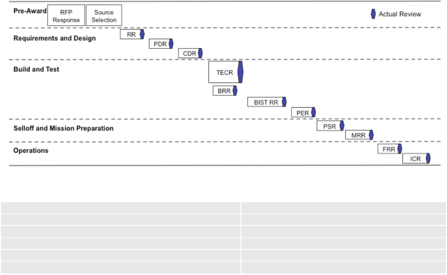
35
4.2 Overview of Space Vehicle Lifecycle Phases
Before an allocation is presented for a risk-constrained program, it is necessary to briefly describe the
Space Vehicle Development Lifecycle Phases since the development and use of Tb&S must be
coordinated with the spacecraft program lifecycle events. For the purposes of this document, the
events of spacecraft lifecycle will be organized as in Aerospace TOR-2009(8583)-8545 “Guidelines
for Space Systems Critical Gated Events”. Figure 4-3 is from this Aerospace TOR, and shows the
critical gated events of a typical program. This top-level timeline shows the program lifecycle broken
into five broader categories: Pre-Award, Requirements and Design, Build and Test, Selloff and
Mission Preparation, and Operations. Since Tb&S products are typically used in all five of these
program phases, the uses typical of each phase and the required simulator maturity typical of each
phase are presented in detail in the following sections.
Figure 4-3. Notional gated event sequencing from aerospace TOR-2009(8583)-8545.
1 - Requirements Review (RR)
7 - Pre-Environmental Review (PER)
2 - Preliminary Design Review (PDR)
8 - Pre-Ship Review (PSR)
3 - Critical Design Review (CDR)
9 - Mission Readiness Review (MRR)
4 - Build Readiness Review (BRR)
10 - Flight Initial Readiness Review (FRR)
5 - Test Evaluation Campaign Review (TECR)
11 - Initial Checkout Review (ICR)
6 - Baseline Integrated Test Readiness Review (BISTRR)
The key program phases are as follows:
• Pre-Award Phase – This is the phase in a program lifecycle that includes all activities in
support of proposal development
• Requirements and Design Phase – This is the phase in a program lifecycle that includes all
activities directed at capturing the program’s system level requirements and developing a
detailed design capable of meeting these requirements.
• Build and Test Phase – This is the phase where System and Subsystem engineers are
verifying and validating requirements. Typical risk-constrained programs with non-heritage
designs benefit from a System Testbed to perform V&V, Fault Management response and
recovery scenarios, C&T database validation, AI&T risk reduction and anomaly resolution.

36
• Sell-Off and Mission Preparation Phase – This is the phase in a program lifecycle that
includes all activities needed to demonstrate that the flight and ground systems are ready for
launch.
• Operations Phase – This is the phase in a program lifecycle that includes all activities
following launch. Included within this phase are any on-orbit checkouts that are performed.
4.3 Allocation of Program Phases to Tb&S Uses for a Risk-Constrained Program
In this section we allocate the Tb&S End Uses to each of the five program lifecycle phases for a risk-
constrained program. Also, a typical Tb&S delivery schedule required to meet the planned Tb&S uses
is provided within the detailed description of the allocation to each program phase, suggesting
handoffs of Tb&S products between the earlier simulators and the later testbeds for a typical program.
We do, however, offer a brief discussion in each subsection that addresses the allocation to a
resource-constrained program without going into the details of each use.
4.3.1 Typical Tb&S End Uses during Pre-Award Phase
Tb&S Products Used in a Risk-Constrained Program
NRT-Sim, NFTB
The Pre-Award phase of the program is generally conducted outside of customer oversight, and
because different programs and different companies vary widely in their practices during this phase,
the activities in this phase are somewhat more difficult to categorize. In general, the pre-award phase
may benefit from re-use of existing Tb&S products (such as NRT-Sim or STB) for concept studies
and concept development in the preliminary system-level design trade studies to support the proposal
effort. Also during this phase, Tb&S products are developed or borrowed from previous programs for
initial risk-reduction studies and proof of concept studies, especially when the Space Vehicle is new.
The End Uses appropriate here are contained within the Concept Development End Use category,
discussed in Section 3.2.1 and the primary Tb&S type used within a risk-constrained program is an
NRT-Sim. For these End Uses, the Proposal Team may benefit from reuse of an existing NRT to
evaluate candidate design solutions and to define a technical baseline for the next program phase.
Depending upon the specifics of the mission described in the Request for Proposal (RFP), the
proposal team may elect to borrow a simulator or testbed from a previous program and refine some of
the simulator parameters to suit the new concepts under study.
The principal schedule driver in the pre-award phase is the Proposal due date. Working backwards
from that date, the Proposal team must have completed design trade studies far enough ahead of the
Proposal due date to allow time for any concept development work needed for the selected design,
while still leaving time for other proposal data collection and writing activities. Therefore these End
Uses will require any simulator or testbed tools before the start of proposal writing, and may continue
to need refinements right up to the Proposal Due date, however ideally their use would be completed
early in the proposal writing schedule.
Note on Resource-constrained Programs: The Tb&S allocation for a resource-constrained program
in this phase should be identical to the allocation for a risk-constrained program, described above. In
both program types, the proposal team uses the Tb&S product most convenient to their needs, and
with the least development effort required.

37
4.3.2 Typical Tb&S End Uses during Requirements and Design Phase
For each program step during this phase of the program, Software and Subsystem engineers are using
simulators and testbeds to develop and test software algorithms, lower level components, and
integrated builds. Since the Requirements and Design phase ends at program CDR, it is usually too
early to have an operational STB, but all the components (software and engineering model hardware)
should be designed and tested for insertion into an STB.
Figure 4-4 shows the Requirements and Design Phase Tb&S usage schedule for a risk-constrained
program. During this phase FSW begins its product development, unit test and integration on
NRT/RT simulators and Non Flight-Like Testbeds (before EMs are available) and performs final
verification on the FSW Test Bench (see Figure 3-9). Subsystems such as EPS may use a Subsystem
Testbed to prove out their algorithms before handoff of algorithms to FSW. Operational Ground
Systems (or the STB Ground System if it is different from Operations) need an NRT simulator to
check out their operations with the SV Command and Telemetry database.
Figure 4-4. Requirements and design phase Tb&S usage schedule.
Note on Resource-constrained Programs: As far as resource-constrained programs are concerned,
because of the compressed timetable typical in the resource-constrained program, these programs will
typically have trouble completing the development of a System Testbed early enough to allow for the
subsequent development and qualification of FSW ahead of the start of AI&T activities. For this
reason, resource-constrained programs typically do not complete FSW qualification until just prior to
pre-environmental performance testing in AI&T. Since the main use of the System testbed in the
Requirements and Design program is the development and test of FSW, all of the boxes with
interfaces to the FSW processors will be either modeled or present as EM (or better) hardware.
However, it is typical of a resource-constrained program to have less flight-like boxes (and
commensurately more simulated or emulated boxes) than in the similar System Testbed used for these
activities in the risk-constrained program. Another feature typical of the resource-constrained
program is the use of non-simulator tools in checking out the command and telemetry database.

38
4.3.2.1 Subsystem Algorithm Development End Use
Tb&S Products Used for a Risk-Constrained Program
NRT-Sim
In a risk-constrained program, this End Use must start shortly after the proposal win and must be
completed early enough to allow time for the development and testing of the FSW units that
incorporate these algorithms and then for the integration and verification of FSW before the start of
STB activities. In this use, Subsystem engineers, like ACS or EPS, require a method to check out
their algorithms before delivery to FSW. Typically, an ACS development team uses a high fidelity
analysis simulation to develop their algorithms and open-loop test cases for FSW ACS algorithm
verification. The real-world dynamics, environment, disturbance and hardware models are often (or
have the opportunity to be) re-used in the STB Dynamics Simulator. The analyst-generated dynamics
test results provide truth data to be used by the STB development team for their post-test analysis.
EPS engineering model hardware units are typically tested prior to CDR to provide data to backup
analyses. Unless the EPS engineer has a comparable analysis simulation to ACS, they are dependent
on integrating the EPS units as a subsystem to prove out their EPS algorithms before delivery to
FSW. The benefit of having an early EPS subsystem testbed provides an opportunity to integrate it in
the post-CDR STB for more closed-loop fidelity.
4.3.2.2 Command and Telemetry Database Integration and Test End Use
Tb&S Products Used for a Risk-Constrained Program
NRT-Sim, STB
In this use, the Database System Integration Team (or Ground Systems Team) requires an NRT
simulator with adequate realism for command sequences to produce predictable telemetry responses.
This use typically starts early in the Requirements and Design phase and must be completed far
enough ahead of the Build Readiness Review for the released database to be used in the script and
procedure development work that is required before Subsystem and FSW verification testing can
begin. Development often continues past the initial release and into the Build and Test phase. As
time progresses, the STB becomes available for use as a higher fidelity verification of commands and
telemetry.
Guideline 07: For any type of SV program, having a common Ground System during System
and Subsystem Testing, AI&T and Operations provides an opportunity to check out and
synchronize the Command and Telemetry database early in the SV development process.
Rationale and Example: Use of a common Ground System throughout the phases of the SV
development process allows Test Engineers to develop procedures and Telemetry pages to be
easily re-used, promotes test-like-you fly and allows the Ground System developer to checkout
their database and ground products early.
4.3.2.3 Flight Software Development and Integration End Uses
Tb&S Products Used for a Risk-Constrained Program
NRT-Sim, NFTB
This subsection covers the allocation of Tb&S products within a risk-constrained program to two
FSW-related End Uses: FSW Unit Test End Use and FSW Development and SI Integration End Use
defined in Section 3.2.2. While an NRT simulator is an appropriate test environment during FSW unit
development, a realistic environment with a real-time operating system and EM processor hosting the
FSW in an open-loop test environment is necessary for FSW integration and verification. During this

39
use, the NFTB includes models of all of the hardware with interfaces to the FSW processor(s). This
verification platform may need to be maintained through the life of the SV development cycle to
update FSW builds to the STB and AI&T and to maintain the FSW image after launch.
Guideline 08: For a risk-constrained program, to enable timely deliveries of verified FSW to
both the STB and AI&T, it is useful for FSW to define a minimum of two FSW builds.
Rationale and Example: The first FSW build should include the C&DH FSW and control of
each of the interfaces; such as a wheel controller interface to check out the commands to the
wheel corresponding with the tach data from the wheel. This build needs to be completed and
delivered to the STB at the start of the Build and Test Phase and needs to be validated in time
for AI&T to begin its integration and test. The second FSW build should be the rest of the
FSW including the subsystem control algorithms, fault management and payload. Depending
on the complexity of the SV, this second FSW build may be divided into even more multiple
builds, which support the SV development. Ultimately, the final FSW build needs to be
completed in time to be validated on the STB (or ISVT if that’s the plan) and before the AI&T
comprehensive environmental tests.
4.3.2.4 FSW Test Development End Use
Tb&S Products Used for a Risk-Constrained Program
NFTB, STB
For FSW Test Development, test engineers require a platform to develop procedures used in FSW
and Subsystem Verification tests. For early preparation, the Test Engineer may draft their procedures
on a Non Flight-Like Testbed. This use requires a Command and Telemetry database and Subsystem
test plans and must be completed in time to run the procedures on the STB. If planned well, a subset
of these procedures (e.g., interface threads and polarity) may be re-run during AI&T on an STB and
provides an opportunity to re-use as-run procedures.
4.3.3 Typical Tb&S End Uses during Build and Test Phase
During the Build and Test phase of the program, System and Subsystem engineers are verifying and
validating requirements on either the STB or ISVT, depending on their program’s resources. Typical
risk-constrained programs with non-heritage designs benefit from a System Testbed to perform V&V,
Fault Management response and recovery scenarios, C&T database validation, AI&T risk reduction
and anomaly resolution.
Figure 4-5 shows the Build and Test Phase Tb&S usage schedule. At the stage when the STB is first
available, the Tb&S products from the Requirements and Design Phase need to be mature enough to
perform System, Subsystem and Fault Management V&V engineering tests, AI&T procedure
development and anomaly resolution. Because of the high cost of AI&T activities, it behooves the
risk-constrained program to perform as much of their V&V activities as possible on the STB,
relegating only interface, polarity and workmanship type testing to AI&T; thus reducing the AI&T
schedule and ultimately reducing costs.

40
Figure 4-5. Build and test phase Tb&S usage schedule.
Note on Resource-constrained Programs: Simulator use during the Build and Test phase of the
program is highly varied, as diverse groups are looking to shift activities off of the flight spacecraft to
venues with less cost and schedule penalties. For a typical resource-constrained program, many of the
uses appropriate to this lifecycle phase end up getting allocated to the ISVT instead of the STB in
order to meet program schedule and cost constraints.
4.3.3.1 System/Subsystem Verification and Validation End Use
Tb&S Products Used for a Risk-Constrained Program
STB
This subsection covers the allocation of Tb&S products within a risk-constrained program for several
End Uses: FSW Formal Requirements Verification (SIQT) End Use, FSW Regression Testing End
Use, System/Subsystem Requirements Verification End Use, and System/Subsystem Validation End
Use as defined in Sections 3.2.2 and 3.2.3. These End Uses are typically required to be complete
before Fault Management and System level System Testbed (STB) testing and the start of AI&T.
Subsystem requirements requiring hardware not present in the STB need to be verified during AI&T.
4.3.3.2 AI&T Risk Reduction Testing End Use
Tb&S Products Used for a Risk-Constrained Program
STB
In this use, AI&T, subsystem or system engineers require a System Testbed with EM or flight
components to perform interface verifications, initial requirement validation, and pre-integration
checkout. The System Testbed allows a program to verify proper operation of hardware, flight
software, ground equipment, or test equipment prior to installation and use on the flight vehicle. The
start point for this use is the availability of appropriate EM units (or Software components) for testing
and generally extends to beginning of system level AI&T.

41
4.3.3.3 Fault Management System Testing End Use
Tb&S Products Used for a Risk-Constrained Program
STB
In this use, Fault Management engineers use an STB to run tests to verify fault management
requirements. In this type of program, the use starts immediately after Subsystem V&V (Section
4.3.3.1) and is ideally completed prior to the AI&T environmental test activities. This testing assumes
the flight vehicle is on the final FSW build and the lower level subsystem level tests are successful
and complete. Fault Management System testing is primarily conducted on an STB, because it is a
safer environment for creating anomalous conditions and because of the ability to inject faults from
simulated components. However, a subset of Fault Management tests that exercise critical flight
hardware components of the Fault Management system may still need to be re-run during AI&T.
Guideline 09: For any type of SV program, perform as much Fault Management testing on the
System Testbed as possible and try to minimize FMS testing against the SV.
Rationale and Example: The STB provides greater capability to inject realistic faults,
providing greater fidelity and robustness for most type of fault testing. This type of testing
should augment tests performed on the space vehicle flight hardware. The risk in omitting or
curtailing this activity is that Fault Management essential to the safety of the Space Vehicle
may contain design or implementation errors that effect on orbit performance and Space
Vehicle safety.
4.3.3.4 Day-In-The-Life Testing End Use
Tb&S Products Used for a Risk-Constrained Program
STB
In this use, System engineers typically require an STB to verify system operational concepts,
including autonomous and ground supported operations, as detailed in Section 3.2.3. Realistic
nominal and off-nominal scenarios are developed in concert with the Fault Management, Subsystem
and Operation Engineers.
4.3.3.5 Flight Operations Training and Mission Rehearsals End Use
Tb&S Products Used for a Risk-Constrained Program
NRT, STB
To accommodate these End Uses, an NRT simulator and an STB are required to provide a training
tool for developing operational scripts to fly the SV and to respond to anomalies. NRT and Non
Flight-Like Testbeds may make an adequate training platform if their fidelity is comparable to or
validated against an STB. This use typically starts in the Build and Test phase, and should benefit
from the Test Like You Fly procedures utilized by the System and Subsystem engineers.
4.3.3.6 Test Procedure Development End Use
Tb&S Products Used for a Risk-Constrained Program
NRT, STB
In this use, AI&T requires an NRT simulator, a FSW Test Bench, or a System Testbed with adequate
realism to provide a platform for dry running procedures. For the development of AI&T integration
procedures, the hardware realism required is typically more than an NRT can provide, and often the
EMs in an STB are also not adequate. For the development of AI&T system-level test procedures, an

42
NRT or an STB is usually adequate. This use typically starts early in the Build and Test phase.
Procedure development for integration procedures should be fundamentally complete before the start
of AI&T integration activities, however procedure development work for system-level test procedures
is better planned to last until just before the start of pre-environmental performance testing.
4.3.3.7 Test Anomaly Resolution End Use
Tb&S Products Used for a Risk-Constrained Program
STB
In this use, AI&T, Subsystem, and System Test Engineers may require a tool to pursue anomaly
resolution offline from AI&T spacecraft operations. They benefit from having an STB to resolve
anomalies offline to reduce AI&T schedule risk. The required fidelity/maturity of the STB will vary
with the nature of the anomaly and benefits from an STB designed with primary and redundant
C&DH and EPS hardware in the loop. This use is a contingency activity that may occur any time in
the Build and Test phase after the start of AI&T activities and may continue during launch and post
launch.
4.3.3.8 Ground Compatibility Test End Use
Tb&S Products Used for a Risk-Constrained Program
STB, ISVT
In this use, the STB (or ISVT when ready) is used for database validation during System, Subsystem
and FM testing. The STB provides an environment to realistically check out the C&T database
between the Ground and the SV, including all the telemetry formats. Hardware commands and
telemetry requiring hardware not present in the STB need to be validated during AI&T.
4.3.4 Typical Tb&S End Uses during Selloff and Mission Preparation Phase
Tb&S Products Used for a Risk-Constrained Program
NRT, STB, ISVT
During the Sell-off and Mission Preparation Phase, Flight Operations continues to develop
procedures, train operators and perform rehearsals. The Tb&S products identified during the Build
and Test Phase continue to be used in this Mission Preparation Phase. The initial training activities
usually start during the Build and Test Phase and must be completed prior to the Pre-Ship Review.
Additional training may continue into the Operations phase of the program. The additional Tb&S End
Use that applies to this phase is Mission Rehearsals. In this use, test engineers, working with ground
station operators, require a tool to dry run operations activities. Typically an NRT simulator, a System
Testbed, or an ISVT is used in the risk-constrained program.
4.3.5 Typical Tb&S End Uses during Operations Phase
Tb&S Products Used for a Risk-Constrained Program
NRT-Sim, STB
During the Operations Phase, Operations and Subsystem Engineers require tools to pursue anomaly
resolution offline from flight operations. These End Users also require tools to continue Operations
procedure development and operator training activities. Typically the Tb&S product developed and
used for Mission rehearsals, Day-in-the-life testing, or Test Procedure development are the preferred
platforms to maintain post launch. Optimally, two Tb&S platforms are preferred during this phase:
1) The STB is the most useful anomaly resolution platform, due to its hardware in the loop fidelity;
and 2) An NRT-Sim (as long as its model fidelity has been validated against the STB) is useful for
43
operators training, due to its ease of use and low maintenance. The Post-Launch Anomaly Resolution
End Use may occur any time in the Operations phase after launch, so the Tb&S must be ready by the
start of this phase.
44

45
5. Lifecycle Process for Program Tb&S Products
This section of the document describes the entire lifecycle of program Tb&S, from the conception to
the operations and maintenance phase. Section 5.1 contains the development lifecycle and identifies
the common activities for each Tb&S development lifecycle phase along with the entrance and exit
criteria for each activity and any required program inputs required during the Tb&S development
activity. Section 5.1 also provides a checklist for each activity, containing recommended tasks to be
performed and artifacts to be produced. Section 5.2 provides information on Tb&S support of the
spacecraft program reviews (i.e., SRR, PDR, CDR). Section 5.3 covers the roles and responsibilities
associated with program Tb&S and offers guidelines for improvement.
Guideline 10: Follow a semi-formal to formal Tb&S development process with clear and
comprehensive requirements and design documentation.
Rationale and Example: This guideline ensures lower-cost reproducibility of Tb&S
components or of an entire Tb&S during later stages in the program when development teams
are different or the users must address any issues with the Tb&S operations.
5.1 Tb&S Lifecycle Process Overview
The development and use of Tb&S products on a spacecraft program typically follows a standard
system product development process. For the purposes of this document, the Tb&S activities for a
spacecraft lifecycle will be organized similar to Aerospace TOR-2009(8583)-8545 “Guidelines for
Space Systems Critical Gated Events”, described in Section 4.2. Since Tb&S products are typically
developed in this manner (See Figure 4-3), the process description used in this section will follow
similar lifecycle phases and corresponding activities organized as follows:
Pre-Award Lifecycle Phase
o Tb&S Proposal Activity (Section 5.1.1.1)
Requirements and Design Lifecycle Phase
o Tb&S Architecture and Requirements Development Activity (Section 5.1.2.1)
o Tb&S Design Activity (Section 5.1.2.2)
Build and Test Lifecycle Phase
o Tb&S Build and Integration Activity (Section 5.1.3.1)
Selloff and Mission Preparation Lifecycle Phase
o Tb&S Verification Activity (Section 5.1.4.1)
Operations Lifecycle Phase
o Tb&S Operations and Maintenance Activity (Section 5.1.5.1)
It should be noted that, since the availability of the Tb&S products constitute a pre-requisite for entry
into some program lifecycle phases, i.e., Requirement and Design or Build and test, their
development phases are offset and typically lead those of the program.

46
5.1.1 Pre-Award Lifecycle Phase
The Tb&S activity during this Pre-Award Lifecycle Phase focuses on the development of sufficient
Tb&S artifacts to support the Proposal Phase of the program.
5.1.1.1 Tb&S Proposal Activity
Proposal development for Tb&S is tailored for each proposal activity based upon the customer
instructions in the Request for Proposal (RFP), Request for Information (RFI), Announcement of
Opportunity (AO), or comparable customer directions.
During the Proposal Activity, as shown in Figure 5-1, it is important to create a set of Tb&S artifacts
so that trades can be made regarding the quantities and capabilities (e.g., level of fidelity and test-as-
you-fly configuration). Using the program’s proposed Verification and Validation plan as their guide,
Systems Engineering in coordination with Tb&S gathers information from all potential users as
discussed within Section 3 of this document. The Tb&S artifacts to be developed during this activity
include; Tb&S Development Plan (see Appendix A), Tb&S Schedule, Tb&S Conceptual
Architecture, and ultimately the Tb&S Task Descriptions (TDs) and Basis-of-Estimate (BOE). These
artifacts will help drive the cost, schedule, and technical proposal decisions that must be made in
deciding the number and types of Tb&S products to be utilized for a given program.
Guideline 11: Include a Tb&S Development Plan as part of the standard Tb&S documentation.
Rationale and Example: Creating a Tb&S Development plan, starting in the pre-award phase
and baselined at the completion of the Requirements & Architecture phase, is critical to
communicating the proposed capability to be developed and deployed. This document can be
subordinate to the programs’ Test & Evaluation Master Plan, and forms the basis for all
activities during the Tb&S lifecycle.
Guideline 12: During the Proposal phase of the program, ensure Tb&S types, quantities, and
capabilities are sufficient to support the projected usage during the execution phase of the
program.
Rationale and Example: Many programs do not fully consider providing adequate number and
types of Tb&S and consequently find that usage is higher than initially assumed. The ensuing
resource bottleneck creates costs and schedule impacts far greater than those that would have
resulted from the extra cost of building more Tb&S at the appropriate time in the schedule.
The usage results will drive the initial Tb&S architecture key requirements and definition.
The Tb&S Proposal Activity’s Entry and Exit Criteria are shown in Figure 5-1. The Entry criteria
include the Proposal RFP/RFI, the Tb&S Users’ needs, the Program’s Verification and Validation
(V&V) Plan and previous Tb&S lessons learned. The Tb&S Proposal Exit Criteria expects a Tb&S
Development Plan, Schedule, Conceptual Architecture and TD/BOEs.
Figure 5-1. Tb&S proposal activity.

47
Tb&S Development Plan: The development plan identifies all the different Tb&S types required
across a Space Vehicle life cycle; including the quantity and fidelity for each type. This plan needs to
reflect the Users’ needs and support the Program’s V&V plan.
Guideline 13: In the initial Tb&S development plan define gates and reviews and ensure that
the entry criteria include input from the appropriate users and development teams.
Rationale and Example: This activity addresses the following: 1) It ensures that all users of the
various Tb&S are given the chance to specify the capabilities they need from each delivery
cycle; 2) It ensures that all appropriate users (such as the Systems Engineering Team) are
involved in the development of Testbeds & Simulators; and 3) It ensures that the usage
schedule by each user is not underestimated. Underestimating the Tb&S usage schedule affects
other users until the schedule slippage propagates to all users.
Tb&S Schedule: The schedule ties all the Tb&S product developments to program life cycle
milestones and need dates. High-level Tb&S giver/receivers anchor the Tb&S developments to the
Users’ needs.
Guideline 14: The Tb&S deployment schedule should satisfy the End User needs during that
program phase. The End Users must accurately specify the capabilities they need from each
Tb&S delivery and the Tb&S organization must agree that their deployment can satisfy the
need.
Rationale and Example: The Space Vehicle and Tb&S development cycles for a typical
program share concurrent development cycles. This necessitates staged capability deployment,
prioritized based on program level requirements. Underestimating schedule by some users
affects other users until the schedule slippage propagates to all users risking critical path
impacts. For example, software-only simulators could be deployed in earlier phases providing
lower fidelity capabilities, but faster time to market, to support development and risk reduction
activities.
Tb&S Conceptual Architecture: The conceptual architecture identifies the physical components of
a Tb&S product; namely what’s hardware in the loop versus what’s modeled, and what ground
support equipment and operator console is required. A conceptual architecture needs to be provided
for each Tb&S type identified in the Tb&S Development Plan. Tb&S Lessons Learned are extremely
helpful in defining the Tb&S Conceptual Architecture.
Tb&S TD/BOE’s: Based on the Tb&S Development Plan for Tb&S types across the Space Vehicle
life cycle and each Tb&S type’s Conceptual Architecture, the TD/BOE’s provide the basis for the
Tb&S developments and Tb&S labor, material and subcontractor costs.
Table 5-1 provides a Checklist to assess the Tb&S Proposal activities and artifacts during the Pre-
Award Lifecycle Phase.

48
Table 5-1. Tb&S Proposal Checklist
Tb&S Proposal Checklist Yes No N/A
Does the Tb&S development plan support the Proposal’s RFP?
Is the Tb&S Development Plan identified in the Proposal’s V&V plan?
Is the Tb&S conceptual architecture and fidelity defined? Reference Section
3.4.2 to define the fidelity levels.
Does the Tb&S fidelity and conceptual architecture meet the V&V plan and
user needs?
Does the Tb&S make use of common EGSE and Ground System
components?
Have all the flight-like components (EMs, Cmd/Tlm database, FSW, harness,
Ground System, EGSE) fidelity been coordinated and costed?
Are all the Tb&S givers and receivers identified in Integrated Management
Schedule (IMS)?
Is the Tb&S on a critical schedule path for any of the Program’s
developments; such as Subsystems, AI&T or Operations?
If the Tb&S is on the critical schedule path, is appropriate schedule slack
identified?
Are all the Tb&S risks identified, prioritized and with mitigation plans?
Do the Tb&S TD/BOEs reflect realistic tasks and budget to complete the
development and are the costs for the flight like components captured in the
current WBS?
Guideline 15: Tie the Tb&S product and its use to the entry criteria for AI&T.
Rationale and Example: This guideline ensures the early delivery of EMs early so the program
gets the value out of their use in a Tb&S product. Often programs do not complete
development and qualification of their component hardware in time (causing schedule erosion),
which naturally shifts priority away from development hardware to direct development of
flight components. This delays delivery of development hardware, rendering it ineffective for
troubleshooting and resolving problems found with flight hardware during AI&T.
Guideline 16: Programs must identify early which system requirements (including key risk
requirements and functions) they plan to validate on which Tb&S platform or which Tb&S
platform they need to collect data for their analyses.
Rationale and Example: The V&V plan should be developed in the earliest phase of the
program so that key requirements including test requirements can be identified and flowed
down to the testbed level. Often tests are designed and tailored based on the capability of the
testbed rather than test requirements driving the testbed requirements. Defining the test
requirements early in the program (even during the RFP) will reduce the overall testbed
development cycle time and an effective V&V process.

49
5.1.2 Requirements and Design Lifecycle Phase
The Requirements and Design Phase of the program lifecycle encompasses the activities between
program Authorization To Proceed (ATP) and the Critical Design Review (CDR) leading into the
Build and Test phase of the lifecycle.
For Program Tb&S products, this activity consists of defining and designing the Tb&S architecture
based on key driving requirements and constraints. The Tb&S requirements may be formal or
informal, but always come from the standard requirements flow-down for the system. Once the
architecture is defined, requirements analysis is performed to derive additional requirements and
flow-down lower level requirements. Trade studies are performed and design options are considered
to establish a baseline architecture that meets requirements and satisfies the End User for their
intended End Uses. The design phase consists of completing a design based on the Tb&S architecture
and requirements.
Guideline 17: The Systems Engineering team must be involved during the development of
Program Testbeds and Simulators. Defined Tb&S gates and reviews will ensure that the entry
and exit criteria include the involvement of the SE team.
Rationale and Example: Since the Tb&S development lifecycle typically involves concurrent
design activities with the Program, Systems Engineering’s role is to provide requirement
updates and to ensure the Tb&S architecture and requirements are aligned with program needs.
For example, during the Tb&S requirements and design lifecycle phase, the Space Vehicle
goes through reviews resulting in requirement and design changes that impact Tb&S. The
Systems Engineering team must have a role in ensuring that impacts to Tb&S are adequately
addressed.
5.1.2.1 Tb&S Architecture and Requirements Development Activity
Development of the Tb&S system architecture begins upon ATP and completes with a review
establishing the baseline Tb&S system architecture and requirements. Figure 5-2 shows the entrance
and exit criteria for the Architecture and Requirements Development Activity as well as the required
program inputs during this activity. Entry criteria include the Tb&S Development Plan (draft), the
initial Tb&S Schedule, the Tb&S Conceptual Architecture, and the Task Descriptions and BOEs from
the proposal activity. If artifacts from the proposal phase are available then they become the starting
point for this activity; if they are not available then they must be sufficiently developed in order to
begin this activity.

50
Figure 5-2. Tb&S architecture and requirements activity.
Functional, Physical, and Interface Architecture: A Conceptual Tb&S Architecture should have
been developed in the Pre-Award activity, establishing a baseline for the technical, cost, and schedule
drivers for Tb&S products. During the Architecture and Requirements Development Activity, a
Tb&S Architectural Plan is developed to meet stakeholder (e.g., Tb&S End User) needs and allocated
requirements. The Tb&S architecture consists of three elements: functional, physical, and interface.
The process starts with a comprehensive identification of all Tb&S End Users, as described in Section
3.1 and Table 3-1. Once the End Users have been identified, development of the End Uses required of
the Tb&S system can be established, as described in Section 3.2 and Table 3-2. These End Uses
define the functionality required of Tb&S as detailed in Section 3.3 and Table 3-3. This becomes the
basis for the Tb&S Functional Architecture.
The Tb&S Conceptual Architecture should have identified the physical components of the Tb&S end
products (i.e., decisions about which components need to be hardware and which can be modeled).
During the architecture activity, a baseline is established for the suite of Tb&S products that support
the End User. This consists of identifying the types, quantities, and fidelity levels of the Tb&S
products that are required for the program (see Section 3.4). The Tb&S Physical Architecture consists
of decomposing each identified Tb&S product into their major components as described in Section
3.4.1. The fidelity levels required for the Hardware (Table 3-5) and Software Models (Table 3-6)
should be initially defined. At the end of this phase, the decomposition should be sufficiently detailed
to begin developing the low-level Tb&S product requirements.
The Tb&S Conceptual Architecture may have identified key interfaces within and external to the
Tb&S. During this activity, critical interfaces are defined as necessary to establish capabilities
required by the functional architecture. Section 3.4.2 can be used to initial identify the required
fidelity levels of the interfaces within the Tb&S system. External interfaces from Tb&S should be
established, including facilities, IT infrastructure, and other key external interfaces. This becomes the
basis for the Tb&S Interface Architecture.
51
Architecture Trade Studies: Trade studies of the Tb&S architecture should be performed in order to
ensure that the planned Tb&S products not only meets their technical requirements, but can also be
deployed on schedule and within the cost constraints of the program.
Tb&S System Requirements: During the Requirements Phase of the program, the requirement
analysis and development activity will begin and mature. The purpose of requirements analysis is to
perform detailed requirements analysis, including both functional and performance analysis, in order
to flow-down appropriate requirements. This process follows the architecture development process
that involves trade studies and various design options to establish a baseline architecture with top-
level requirements identified ahead of the design activity. The Requirements and
functional/performance analysis processes often continue into the Tb&S design activity with updates
to the artifacts established in this activity.
The requirements activity is critical to ensuring completeness and accuracy of the final Tb&S
products. Effective communication and collaboration with all stakeholders avoids problems with
Tb&S functionality and fidelity being under- or over-specified for the identified End Use.
Figure 5-3 shows an example of requirements flow down and specification of program artifacts to the
Tb&S System Requirements. The Tb&S requirements are derived from various system and
subsystem specifications such as: Ground Requirements (i.e., CMD/TLM); System level functional
and performance requirements; Operational scenario and Operations requirements (i.e., training
requirements); and direct flow-down from the contractual requirements. The primary purpose of this
tree diagram is to identify requirement sources and identify key Tb&S requirements that need to be
specified in both system level specifications and component level specifications, if required by Tb&S
Development Plan.

52
Figure 5-3. Example requirements flow-down and specification tree.
Tb&S Development Plan: The initial Tb&S Development Plan created in the Pre-Award activity
should be updated to include all baseline decisions resulting from this activity. At this point the
document should be comprehensive and under change control, as it establishes the baseline plan from
the completion of the development and deployment of Tb&S to support the program. The
development plan may be considered a living document to be updated as the program matures unless
other artifacts are planned to support remaining lifecycle activities.
Other Considerations: The Tb&S Top-Level schedule created in the Pre-Award Activity must be
refined to adequately define the major Tb&S development activities, Tb&S product deployments, and
critical giver-receiver dependencies with other program organizations. This should include key
dependencies to EGSE, Subsystem organizations (for EM deliveries), System Analysts, and the I&T
organization. Tb&S should identify all top-level risks and develop plans for risk burn-down. Any
opportunities associated with Tb&S should be identified for program consideration.
53
Guideline 18: Hold a Tb&S System Requirements Review (SRR). All findings and action
items should be documented and work products should become the Tb&S baseline.
Rationale and Example: It is important that the Tb&S Architecture and Requirements baseline
be established and communicated to key program stakeholders. Tb&S End Users must attend
this review to ensure that the technical and schedule baseline meets their needs. Program
management must be informed as to the importance that the Tb&S products contribute to the
overall program development, integration and test, and operations phases of the program.
Guideline 19: Early involvement of System and Subsystem Subject Matter Experts (SME)
during the requirement definition phase of Tb&S helps provide domain expertise critical to
requirement development.
Rationale and Example: The top level requirements involving system technical performance,
Subsystem partitioning and capability definition would benefit greatly with inputs and
influence from Subsystem SMEs early on in the architectural phase as they provide foresight
into the End Uses, for example providing a modular simulation architecture or a distributed
processing would provide for greater system scalability and configurability.
Guideline 20: Ensure the Tb&S system can be controlled from the program ground system.
Rationale and Example: This provides users with the capability to have connectivity between
the test procedure, the flight commands, and the GSE commands.
Guideline 21: Make Tb&S software configurations flexible by making them parameter-driven
so that changing configurations does not require rebuilding the Tb&S software.
Rationale and Example: Enabling parameter-driven reconfiguration of the Tb&S (such as
changing the orbit) will significantly reduce the cost of developing and operating Testbeds &
Simulators and may protect the Testbed from any cost-cutting measures in cases of schedule
erosion.
Table 5-2 provides a Checklist to assess the Tb&S Architecture and Requirements activities and
artifacts during the Requirements and Design Lifecycle Phase.
Table 5-2. Tb&S Architecture and Requirements Activity Checklist
Tb&S Architecture and Requirements Activity Checklist
Yes No N/A
Are all entrance criteria met for the Architecture and Requirements
Development activity?
Have all Stakeholders and their Needs been identified prioritized?
Have all the Stakeholders been identified?
Note: Refer to Tb&S End User Taxonomy
Have all stakeholder needs, expectations and constraints been analyzed?
Note: Refer to Tb&S End Uses Taxonomy and Functional Taxonomy
Have the stakeholder needs for each identified End Use been mapped to key
Tb&S deployment milestones?

54
Tb&S Architecture and Requirements Activity Checklist
Yes No N/A
Have the Tb&S limitations and constraints been identified for all phases of the
lifecycle?
Have Tb&S risks been identified and is a preliminary risk analysis complete?
Have the Tb&S system objectives & Tb&S product deliverables been
defined?
Has a system level functional analysis been conducted to derive key Tb&S
system requirements?
Note: For each identified use, for each milestone.
Has a problem statement been developed that succinctly outlines the Tb&S
system objectives?
Note: For each Tb&S End User.
Have the Tb&S System Requirements been completed and reviewed?
Has a Concept of Operations (ConOps) been evaluated for its impacts to
Tb&S?
Have trade studies been conducted and analyzed to further decompose
architecture and requirements?
Have trade studies been conducted to analyze/justify make/buy/re-use
decisions?
Have internal reviews for Tb&S artifacts been conducted to obtain internal
Subject Matter Expert (SME) and technical staff feedback?
Has the Tb&S Functional, Physical, and Interface Architecture been
developed and reviewed?
Have key Architecture drivers been identified? Technical, Schedule & Cost
Have lessons learned from previous programs been reviewed and
implemented?
Note: Identify improvements to save cost and schedule
Has the Tb&S Hardware architecture been developed?
Has the Simulation architecture been developed?
Has the Database architecture been developed?
Has a preliminary Tb&S Data Management architecture been developed?
Real-Time Data I/O distribution, Data archiving
Has Software Configuration Management (SCM) system that supports Tb&S
been developed?
Note: SCM product identified and reviewed?
Are all work product packages released and baselined?
Has there been adequate participation in the architecture and requirements
review?
Are all exit criteria met for this Activity?
5.1.2.2 Tb&S Design Activity
The Tb&S Design Activity can begin once the baseline system architecture and system requirements
have been established. This activity usually occurs in two parts: Preliminary Design, and Detailed
Design. The Entry and Exit Criteria for the Design Activity are shown in Figure 5-4.

55
Figure 5-4. Tb&S design activity.
Preliminary Design: During the Preliminary Design, trade studies are performed to determine the
optimal solutions for the End Users and End Uses. Given that Tb&S End Uses have been validated
and that the physical, functional, and interface architecture has been established, the preliminary
design activity includes a decomposition of the architecture and requirements sufficient to perform a
more detailed design on each identified component.
A typical Tb&S product consists of both Hardware Configuration Items (HWCI) and Software
Configuration Items (SWCI). Tb&S product hardware design consists of Configuration Item (CI)
decomposition to lower level components and subsequent design trades necessary to support “make”
vs. “buy” decisions. A buy decision can result in a decision to procure a COTS item or a decision to
initiate a subcontract to have a third party design and fabricate the component. A make decision will
result in a set of preliminary design artifacts sufficient to addresses the high-level Tb&S
requirements.
Guideline 22: During trade studies and architectural development phase, considerations must
be made for portability and modularity during the design of the software components.
Rationale and Example: In order to maximize reuse of the developed software, i.e., simulation
models, it is important to consider an architecture that employs modular design of software
simulation models. Software models are developed individually and independently and
integrated in the simulation environment to create customized dynamics simulation
configurations.
Detailed Design: The Detailed Design process follows the Preliminary Design process to further
decompose the design and perform appropriate synthesis to finalize the design. In this stage the high
level architecture design and system requirements are translated into the lower level design and
requirements. The result of the detailed design process is a collection of artifacts including a set of
released design engineering documents for the Tb&S products, the Tb&S requirements, the build and
test schedule, and a bill of materials (BOM) for building the Tb&S products. The formality and scope
of the engineering documents depends on the requirements of the program and the standards of the

56
contractor. The requirements should be refined and finalized and the corresponding verification plans
should be developed. The resulting detailed design will serve as the basis for entry into the Build
Phase. A CI design is complete for a procurement decision (e.g., “buy”) after an assessment of the
vendor specification is analyzed against the requirements and a Bill of Material (BOM) is produced to
identify the vendor name, part number, quantity, and cost. A decision to subcontract the CI design
and fabrication requires development of a set of subcontract documents resulting in a contract to
design and deliver the product according to a Statement of Work (SOW) and specification. The
design process is complete when the subcontractor successfully demonstrates the completion of the
design portion of the subcontract. The decision to “make” the component in-house follows standard
design processes resulting in hardware and software design artifacts.
Tb&S System Design Artifacts: Facility and Infrastructure requirements should be levied by the
Tb&S group to support the build, test, and deployment of all Tb&S products according to the baseline
schedule. This typically includes physical space, cooling, power, servers, data storage, and IT
network requirements. Engineering drawing of all identified components as to their location and
interconnection (e.g., racks, rack elevations, components/modules in racks, SW deployments to
computing resource, etc) are released during this activity.
Other Supporting Artifacts: An initial Tb&S Test Plan and O&M plan is developed during this
activity. Standard processes outlined in the Tb&S Development Plan are put in place during this
activity like configuration management, change management, establishment of any boards (i.e., HW
& SW Review Boards, etc), and other processes necessary for the design and build phase.
Not all of the program subsystem specifications are released when the Tb&S is being designed since
the Tb&S products are typically designed and built before the flight equipment. Changes to
unreleased specifications should be monitored to identify impacts to the Tb&S products.
Guideline 23: Hold Tb&S design reviews conducted with peers and stakeholders and with all
findings and action items closed Work products released and baselined.
Rationale and Example: Consider reviews for each Tb&S product; stress the importance of
including the stakeholders.
Table 5-3 and Table 5-4 provide Checklists to assess the Tb&S Design activities and artifacts during
the Requirements and Design Lifecycle Phase for the Preliminary Design Activity and for the
Detailed Design Activity, respectively.
Table 5-3. Tb&S Preliminary Design Activity Checklist
Tb&S Preliminary Design Activity Checklist
Yes
No
N/A
Are all entrance criteria met for the preliminary design phase?
Have all task inputs been reviewed and analyzed?
Have relevant lessons learned from previous programs been reviewed and implemented?
Have trade studies and risk analysis on design approach been performed?
Has high level design description been created and evaluated?
Has a preliminary Tb&S design document to capture refined Tb&S product architecture
and requirements been created?
Has there been participation in the Design Review?
Are all exit criteria met?

57
Table 5-4. Tb&S Detailed Design Activity Checklist
Tb&S Detailed Design Activity Checklist
Yes
No
N/A
Are all entrance criteria met for the detailed design phase?
Have all task inputs been reviewed and analyzed?
Have relevant lessons learned from previous programs been reviewed and
implemented?
Has make/buy analysis been Performed (Product acquisition analysis)
Has detail design analysis and evaluation been completed?
Has Tb&S design document been reviewed and changes been properly
incorporated?
Have all systems and subsystem requirements been reviewed and changes
incorporated?
Are Tb&S system and subsystem specification documents ready for release?
Is design under configuration control?
Has there been participation in the Design Review?
Are all exit criteria met?
Are Tb&S Verification Cross Reference Matrix (VCRM) and Verification
Plan completed?
Does the detailed design include the necessary descriptions and artifacts for
manufacture?
If the SV is built in-house, are the make/buy decisions for the Tb&S product
documented somewhere?
5.1.3 Build & Test Lifecycle Phase
Once the Tb&S Design Activity has been completed, the Tb&S products are ready for build,
integration, and test. The first part of this phase is to ensure the completed design is acquired or built
according to the specifications. The Tb&S plan that is developed and matured during the previous
Tb&S activities of the program includes Tb&S Verification Plan to drive the Tb&S integration and
test process. Having a well-planned system integration activity ensures that each of the system
elements comes together and performs as a complete system. Specifically, this activity involves the
integration of various components, subsystems or systems that make up the Tb&S product, as well as
the integration activities within each of the segments themselves (i.e., subsystem EMs).
The Tb&S integration consists of the methodical assembly or interconnection of system elements into
an overall functional system. An element may be a Configuration Item (CI) or a subsystem
comprised of two or more integrated CIs. Integration begins with the delivery of an element for
integration into a system configuration, and ends with a limited demonstration that provides evidence
of the satisfactory operation of each element in the final system. The components or subsystems may
have already had their performance characterized or verified through separate test and evaluation.
5.1.3.1 Build & Integration Activity
The Tb&S Build & Integration Activity, shown in Figure 5-5 below, follows the Tb&S Design
Activity and involves the acquisition/build of both hardware and software components and
subsystems. This build activity could occur in parallel and provide for incremental deliveries for
integration and test. Due to this incremental capability of build and integrations, it may be useful for
the developer to use portions of the checklist (Table 5-5) provided below at various major phases of
the activity to ensure that individual increments of build and integration are on track.

58
Figure 5-5. Tb&S build and integration activity.
Integrated Tb&S Product and As Built Documentation: During the Tb&S product build, all
required hardware and software are purchased or created. As the build proceeds it is important to
have a robust configuration control in place and to update, maintain, and/or compile the as-built
documentation on the product in the Tb&S system. As-built product documentation is a required exit
criterion from this activity to ensure that the next activity of verification has a known, documented
baseline.
Guideline 24: Develop and implement an adequate sparing plan.
Rationale and Example: It is during the acquisition of components that the developers will
know how many spares are on hand and what items may become spares as the product reaches
the end of its life. This information will quickly evaporate if not passed on in a means that
preserves the knowledge of where to find spares and how many spares have been produced.
During the Tb&S integration process, pieces of a software or hardware system are integrated to show
compliance with requirements, architecture, and design. The integration testing includes combining
HW and SW components, COTS, government-off-the-shelf, and subcontracted products for
subsequent integration and testing. Integration and integration testing using different or repeated tests
may take place multiple times during iterative builds.
Guideline 25: Integration activities should be performed on hardware that is as close as
possible to the actual product hardware.
Rationale and Example: Hardware and software integration issues should be identified as early
as possible in order to discover and correct them on actual flight hardware and software
products. A plan to perform integration and testing on products that closely match the final
products will benefit the program in many ways
The focus of integration is verifying new and existing interfaces and functionality such as the
following:
• Integrate and test all new software to software interfaces
• Integrate and test all new software to hardware interfaces
• Integrate and test all new hardware to hardware interfaces
• Demonstrate functional capabilities of end item
59
Guideline 26: Ensure that End Users are involved in the build and integration activity of a
Tb&S product.
Rationale and Example: As the integration tests are performed, early involvement of Tb&S
End Users with some of the use cases identified in Section 3 will benefit both the Tb&S
developers and the users in identifying requirement flaws or potential for requirement growth.
Guideline 27: As part of preparing for the integration and test process, any Tb&S requirements
should be reviewed to determine if they must be verified at a low level which may only be
available during this integration activity.
Rationale and Example: Although overall verification of the Tb&S product is not performed at
this stage, individual pieces of verification may not be available once fully integrated and thus
must be performed as part of integration testing.
Initial User Documentation: The details of how the Tb&S is actually operated begin to become
realized during this activity. The team performing the integration inherently has to start using
portions of the Tb&S and therefore start to generate a method of operations for its hardware and
software. It is at this point that some of the initial user documentation is created. This will serve not
only as a good starting point for the final user documentation, but as a reference guide to be used
during the integration process as inevitably multiple people try to learn how to do the same activities.
This user documentation may consist of procedures, manuals, logs, or other such documentation as
further defined in Section 5.1.4.2. As an example, one item the user documentation should cover
would be the method for how to efficiently switch the configuration of the system between different
user environments. The documentation may be generated by the Tb&S developers or it may be
provided by external sources. Final user documentation is discussed in more detail in Section 5.1.4.2.
Tb&S Verification Test Procedures: An additional exit criterion for this phase is the Tb&S product
verification procedure that will be used in the next phase (see Section 5.1.4). The integration
processes used provides a great source for verification procedures. The compilation of the integration
test plans and procedures used throughout the iterative integration cycle provides a baseline for what
the verification test procedure should contain.
Table 5-5 provides a Checklist to assess the Tb&S Build and Test activities and artifacts during the
Build and Test Lifecycle Phase.
Table 5-5. Tb&S Build and Integration Activity Checklist
Develop Build and Integration Plan
Yes
No
N/A
Has the schedule for phased build and deployment been developed?
Has a review board been formed for Tb&S products?
- Tasked with review and approval of change requests to requirement
baseline.
Has a Peer Review Process been defined consistent with program
requirements?
Has a Defect Tracking and Resolution system been defined and deployed?
Hardware Make/Buy
Have long lead items been procured?
Have impacts of long lead items been addressed in the integration and
deployment schedules?
Have COTS products been procured?
Has test control system been developed or procured?

60
Develop Build and Integration Plan
Yes
No
N/A
Are internal/external cable harness assemblies built/ procured?
Have EGSE or STE hardware subsystems been developed?
Have the test facilities been identified and built?
Has IT infrastructure equipment been procured, installed and configured?
Has simulator hardware equipment been procured?
Software Make/Buy
Have STE software and Firmware been developed?
– Hardware/Bus interface emulation, Device driver firmware
Have Simulation models been developed and integrated?
Have all required data/database items been delivered?
Documentation and Test Development and Release
Has as-built documentation been completed?
Has an integration test plan been developed?
Have test description documents been created and released?
Have test procedures/scripts been developed, reviewed and released?
Has Verification Cross Reference Matrix (VCRM) and/or other requirements
documents been reviewed to confirm requirements and their proposed method
for verification? T-Test, I–Inspection, D-Documentation, A-Analysis
Have software or hardware tools required to perform tests been identified and
allocated?
Tb&S Integration Test Execution
Have End Users been involved in the SW integration and test process?
Have all Unit Tests been performed and succeeded?
Have all integration test peer reviews been completed?
Have Tb&S integration tests been performed?
Are all post test analysis completed?
Has an integration test report been created?
Other Closeout Activities
Have the verification test procedure(s) been developed?
Have all problem reports been resolved or dispositioned?
Has initial user documentation been developed?
Does the user documentation include a sparing and maintenance plan?
5.1.4 Sell-off and Mission Preparation Phase
The Tb&S activity during the Sell-off and Mission Preparation Phase focuses on the Tb&S
Verification activities and documentation.
5.1.4.1 Tb&S Verification Activity
The last activity in the Tb&S development, as shown is the verification (aka Acceptance,
Accreditation, Sell-Off, Certification or Ready-for-Use (RFU)) of the Tb&S. Verification tests may
occur throughout the development and maintenance cycles. Since this activity discusses verification
against requirements, considerations of when verification tests are performed should be identified in
the Tb&S Development Plan. The purpose of the Tb&S Verification activity is to demonstrate the
Tb&S meets all its requirements as mapped in the Tb&S VCRM.
The Entry/Exit criteria for the Tb&S Verification Activity are shown in Figure 5-6. The Entry Criteria
includes the Build and Integration Activity Artifacts from Section 5.1.3.1. The Exit Criteria includes a

61
Verified Tb&S Product, Completed Tb&S User Documentation and a Verification Test Report.
Section 5.1.4.2 details the Tb&S User Documentation.
Figure 5-6. Tb&S verification activity entry/exit criteria.
Verified Tb&S Product: Whether the Tb&S is deployed for the first time or redeployed after its use
on a given program, the Tb&S typically requires some form of acceptance testing and Verification
Test Report at delivery and prior to formal use. Tb&S Verification may be accomplished by analysis
and simulation, inspection, demonstration, test, or a combination of these at any level of the design.
To ensure the Tb&S meets its requirements, an acceptance test procedure needs to be developed,
reviewed and successfully executed to demonstrate that the Tb&S is RFU. This acceptance procedure
should verify that the software and hardware interfaces meet requirements specifications (both in
format, timing and functionality) and that the Dynamics Simulator software models execute as
expected by the analysts and/or the SMEs. This baseline acceptance test, composed of a set of test
cases defined to prove the Tb&S is operational, should be completed before the Tb&S is put into
operations. The Tb&S acceptance test typically assumes that Tb&S deliverables such as the
Dynamics Simulator, EGSE, and all prime hardware and software items, each have executed their
own acceptance test to prove their functioning and performing per their design. Once these
deliverable items are integrated in the Tb&S, the Tb&S acceptance test is performed as a precursor to
performing user dry run and formal V&V tests.
Verification Test Report: The purpose of this document is to provide an overall assessment of the
acceptance testing performed on the Tb&S product. The Test Report shall be used to document the
acceptance test results; including the as-run acceptance test(s), as-needed data trends and summarized
results.
The initial Tb&S use may occur as early as the Tb&S has been integrated to a level wherein it is able
to perform some aspects of its intended job. Since a Tb&S may be developed over time with
increasing fidelity, there should be continuing verification after any upgrades that the Tb&S
functionality still meets the End Users requirements. An example of an early use case is a C&DH test
including the command and telemetry database, FSW, C&DH unit(s), and harness; which may not
need a Dynamics Simulator. In this instance, the Tb&S may be “delivered” for this use much earlier
than it would be ready for a complete closed-loop ACS or fault management test. Due to this flexible
definition of delivery, it is important to always ensure that the Tb&S is at its appropriate level of
fidelity for a given test. It should be noted that this initial baseline delivery and all subsequent
deliveries should be under configuration control. Even though a Tb&S may be in use by a certain
user, it may not have the capabilities implemented to function for all intended users. This issue is
solved with constant communication between the developers, the users, and the entity managing the
Tb&S operation and schedule.
Table 5-6 provides a checklist for the Tb&S Verification activity. This activity includes the
preparation for the Tb&S Verification test, the execution of the test and the exit review tasks for a
verified Tb&S product during the Sell-off and Mission Preparation Lifecycle Phase.
62
Table 5-6. Tb&S Verification Activity Checklists
Tb&S Test Readiness Review
Yes
No
N/A
Has a Tb&S Verification Test Plan been released?
Are the Tb&S requirements mapped to a verification method?
Have all Tb&S Problem Reports been Dispositioned? Are all Tb&S Liens
identified and dispositioned?
Have all Tb&S Verification test procedures been dry run with all findings
addressed?
Are all Tb&S software and hardware documentation released and under
configuration control?
Has a Test Readiness Review (TRR) package been prepared to be presented
at the review?
Has authorization been obtained from Stakeholders to proceed with
Verification Tests (with or without liens)?
Tb&S Verification Test Execution
Has Test Conduct been defined and coordinated with Stakeholders?
– Test Roles, Audits, Pre &Post-test Reviews
Are limitations to “Test Like You Fly” understood and approved?
Have Lessons Learned from previous/similar tasks been reviewed for
applicability to the Hardware, Software and/or Facility?
Are pretest meetings/briefings planned? Are task briefings planned during
the Tb&S verification execution?
Have the engineering support personnel for the test been identified and
scheduled?
Has the Tb&S operations schedule been established? Have shift change
policies and handover procedures been identified?
Has QA participation been coordinated to verify the success of the Tb&S
Verification tests?
Tb&S Post Verification Test
Are all Post Test Analysis completed?-
Has a Tb&S Verification Test Report been created?
Has a Test Exit Review (TER) been scheduled?
Is the Tb&S certified/signed by the stakeholders?

63
5.1.4.2 Tb&S User Documentation
The Tb&S Acceptance documentation includes the deliverable product documentation and the Tb&S
Deployment (i.e., operations and maintenance) documentation as shown in Figure 5-7.
Figure 5-7. Example of Tb&S acceptance document flow-down.
Documentation Deliverable to Tb&S: Each software and hardware item deliverable to the Tb&S is
expected to come with a set of documentation containing its description, capabilities and acceptance
pedigree.
The EGSE documentation should include an as-run acceptance test, which records the configuration
of the hardware and software. Any EGSE changes need to be tracked and evaluated to determine
whether the acceptance tests need to be repeated.
The Dynamics Simulator documentation should include an as-run acceptance test and identify
software required for the simulator to function. The acceptance test records the configuration of the
hardware and the version of the software it was tested against. A list all the software components, in
a form of a Version Description Document (VDD) or equivalent, and how the software was tested,
linked and compiled should be included. Hardware and software changes need to be tracked and
evaluated to determine whether the acceptance tests need to be repeated for future delivery updates.
EGSE Acceptance
Procedure Doc
As-Run Procedure
Testbed Ready
for Use
EGSE
Engineering
Models
Dynamics
Simulator
Testbed
Harness
FSW
Gnd System
w/Cmd/Tlm
Database
Engineering Model
Acceptance
Procedure Doc
Dynamics Sim
Acceptance
Procedure Doc
Dynamics Simulation
Software VDD
Testbed Harness
FAC Test Doc
Flight Software VDD
Gnd System
Acceptance
Procedure Doc
As-Run Procedure & SW VDD
Testbed
Deployment
Docs
Requirements
and Description
Doc
Plans &
Procedures
:
• Mechanical/Electrical
Integration
• Power Up/Down
• Acceptance Test
• Maintenance
Users’ Manual
Logs
• Problem Report
• Configuration
• Mate/Demate
• Operators
As-Run Procedure
As-Run Procedure
FSW VDD
As-Run Procedure
64
Engineering Model (EM) hardware documentation is to include the EM as-run acceptance test. There
should be a goal to keep the EMs up-to-date with the flight hardware; especially if timing and
interfaces are impacted by the change. Any EM changes need to be tracked and evaluated to
determine whether EM or full Tb&S acceptance tests need to be repeated. Depending on the work
structure of the program, this may not be the responsibility of the Tb&S users or developers
(especially if it is assumed to be of no impact to the Tb&S); however the users and developers should
be provided information on the change and what testing will be repeated. This will help ensure that
that any potential impact to Tb&S operations is uncovered.
Tb&S Harness documentation should include an as-run acceptance tests. Examples of tests include;
high voltage pin-to-pin continuity and isolation test to ensure there are no harness manufacturing
flaws and shorts.
The Flight Software documentation should include the software listing (VDD or equivalent) all the
software components and how the software was tested, linked and compiled. The documentation
should also include the command and telemetry database list.
The Ground System documentation should include an as-run acceptance procedure identifying the
version of ground software and command and telemetry database it was tested against.
Tb&S Deployment Documentation: As shown Figure 5-7, a Tb&S Requirements and Description
document, a set of procedures (Power Up/Down procedures, and Special Configuration Utilities),
Maintenance Plan, Users’ Manual, as-built drawings, and Tb&S Logs (Problem Report,
Configuration and Operators) are necessary to successfully operate the Tb&S. These procedures,
plans, manuals and logs are necessary to power up and down, operate, and maintain configuration of
the Tb&S. The level of formality for the Tb&S documentation type, release process and standard
format is an important consideration that needs to be addressed at the start of the program by
consulting program management and customers (internal and/or external users). Required deliverable
documentations and level of formality during the Tb&S operations should be determined based on the
end user needs.
The Tb&S Users’ Manual should describe all the Tb&S features, initialization and configuration
options, including the Tb&S Critical Item Control Plan and any operational constraints. It should
provide operators all the steps they need to take to develop and run their specific procedure.
Furthermore, a standard procedure to power up and down the Tb&S is necessary to maintain a known
test configuration. Options in the procedure should be provided to power up and initialize the Tb&S
to the Users’ needs. This procedure may be provided by the simulator developer, or developed by the
end users.
The Tb&S Maintenance Plan should define the process for the maintenance of the hardware and
software (HW/SW) components, including the type of regression testing required to preserve the
Tb&S Ready For Use certification. This plan should also address the Tb&S sparing and obsolescence
strategy.
The Tb&S logs developed and maintained by the users are necessary to track daily operations and to
provide a record of activities on the Tb&S. These records act as a journal for test events, provide
troubleshooting information, and allow test operators to track problems and system configuration. In
a program with a formal handoff structure the operator’s responsibilities for logging should be clearly
stated in the operating guidelines or Users’ Manual. The Operators log is used to track all the events
of the day; including what procedures are run, any issues observed, changes in configuration and any

65
successes and failures. The Operators log entries are usually the precursor to identifying problem
reports and configuration issues. There may be different levels of formality when developing and
maintaining Tb&S logs that must be considered and defined ahead of time.
Guideline 28: The Tb&S developers should determine the formality of deliverable User
Documents (Requirements, Manuals, User’s Guides) at the start of the program by
coordinating with the customer or the program office or with the program Tb&S product End
Users.
Rationale and Example: Having a formal documentation flow-down and deliverable
requirements during the Tb&S operations phase may not be suitable for every program. For
example, smaller programs with less complex Tb&S, may not require formal documentation
deliverables delaying their Tb&S deployment.
Section 6 provides more details to the type of operational considerations and documentation
necessary for Tb&S operations.
5.1.5 Operations Phase
The Operations Phase consists of the Tb&S Operations and Maintenance Activity after the Tb&S is
verified and deployed. Tb&S Operational Considerations are discussed in detail in Section 6.
5.1.5.1 Tb&S Operation and Maintenance Activity
The Tb&S Operation and Maintenance Activity, as shown in Figure 5-8, assumes the Tb&S is
verified (certified, operational and ready for use). The Tb&S Operations activity includes performing
scheduling, problem tracking and reporting, and other standard operational processes in support of
higher-level program phases (e.g., I&T, V&V, launch, and on-orbit operations, etc). The Tb&S
Maintenance activity follows the Tb&S Maintenance Plan to keep the Tb&S operational and deal
with obsolescence concerns during its lifecycle.
The Tb&S Operations and Maintenance Activity’s Entry Criteria includes the Certified Tb&S with
Stakeholders concurrence, Users Manual and Maintenance Plan. The Tb&S Operations and
Maintenance Activity Exit Criteria is a Tb&S in Operation and actively maintained.
Figure 5-8. Tb&S operations and maintenance activity.
Tb&S in Operation: The extent of this activity depends on the Program contract or if the company
is the owner, its next use (deployment on another program, storage or surplus). Section 6 provides
operational and maintenance considerations.

66
Table 5-7 provides a Checklist to assess the Tb&S Operations and Maintenance activities and
artifacts during the Operations Phase.
Table 5-7: Tb&S Operations and Maintenance Activity Checklist
Tb&S Operations and Maintenance Checklist
Yes
No
N/A
Are the program and user needs for the Tb&S Operations & Maintenance
phase identified?
Has a Sparing and Obsolescence Strategy been identified? Is there a list
identifying all hardware spares?
Has a Tb&S Maintenance Plan been developed? Does it include a plan for
addressing EM and software modifications and updates? Does it include a
standard and readiness maintenance plan?
Has a well-defined regression test strategy been developed?
Is there a Tb&S Users’ Manual?
Is there a Tb&S User Log book?
Is there documentation for the Tb&S hardware and software components
including ( if applicable), EM End Item Data Packages, drawings,
acceptance data?
Has a Point Of Contact list been compiled and posted in the Tb&S area?
Have all test personnel been made aware of what to do and not to do in the
event of a problem or failure in test?
Has the proper training been identified for a test engineer to be approved to
run tests on the Tb&S?
Have specific personnel assignments been made and are responsibilities
understood?
Is the chain of command established and understood by all stakeholder
organizations (i.e., facility, project personnel, contractors, etc.)?
Has a Tb&S utilization schedule and user prioritization method been
identified?
Does the Configuration Management log identify all the Tb&S hardware
and software configured items in the Tb&S?
Is there a common Problem Reporting tool to disposition problems found
during Tb&S testing?
Is instrumentation calibrated and are the test equipment calibration stickers
intact? Is there a plan in the Tb&S Maintenance Plan to keep the equipment
calibrated for the duration of the Tb&S use?
Is there a mate/de=mate log? Has the mate/de-mate log and status of all
connectors been reviewed and the impact to test understood?
Are the Tb&S security, safety and training guidelines identified and
followed?
Is there a plan and schedule to perform special hardware and software tests;
such as one-time hardware compatibility tests?
5.2 Tb&S Support of Program-Level Reviews
The development and use of Tb&S on a spacecraft program requires a coordination of the
development schedule for Tb&S with the spacecraft program lifecycle events. During the Tb&S
development process, critical program milestone reviews will be conducted (i.e., SRR, PDR, and
CDR) that require support as defined in this section. These program-level reviews are as described in
Aerospace TOR-2009(8583)-8545, “Guidelines for Space Systems Critical Gated Events”. The
67
maturity of the Tb&S based on Section 5.1 drives the content that is presented at the actual
development phases of the program itself.
5.2.1 Tb&S Support to Program SRR
This review is the first major review in the program following the proposal phase, and is an
opportunity for the Tb&S team to present their overall concept to the program and customer. The
Tb&S Conceptual Architecture should be presented along with the top-level schedule including major
Tb&S development and deployment milestones.
5.2.2 Tb&S Support to Program PDR
This review is the opportunity for the Tb&S team to present their design for the baseline program
Tb&S to the customer. The current Tb&S architecture (functional, physical, and interface) and
baseline system requirements should be presented along with the top-level schedule, major Tb&S
milestones, and all significant risks or potential opportunities. If possible, the Tb&S team should
present their preliminary design products including trade results, requirements trace to Tb&S end
products, and plans for V&V of the identified products. Program presentations for other products that
require Tb&S capabilities should be reviewed to ensure that any dependencies are properly
communicated.
5.2.3 Tb&S Support to Program CDR
At this review, the Tb&S team will present their completed design for the baseline program Tb&S to
the customer. The Tb&S architecture, requirements, schedule, upcoming Tb&S milestones, and
remaining risks should be presented. The Tb&S team should present their detailed design products
including specifications and interface documents for lower-level Tb&S components, make/buy plans,
final V&V plans and schedule, and transition plan for deploying the Tb&S products. Program
presentations for other products that require Tb&S capabilities should be reviewed to ensure that any
dependencies are properly communicated.
5.2.4 Tb&S Support to Program TRR
This review does not directly map to a particular Gated Event, and is intended to include any
program-level reviews that require any Tb&S products for formal V&V efforts. The Tb&S
presentation should include required artifacts to support the review.
5.2.5 Tb&S Support to Program PSR
At this review, the Tb&S team will present the current capability and status of program Tb&S
supporting final closeout activities as well as planned support for launch and early operations.
Program presentations for other products that require Tb&S capabilities should be reviewed to ensure
that any dependencies are properly communicated.
5.3 Tb&S Roles and Responsibilities
As set of individuals with certain skills is required to plan, develop, deploy, and operate the suite of
Tb&S associated with a space vehicle development program. The Tb&S organization has been found
to live in a variety of places within the program organization as shown in Figure 5-9, as found in a
survey of industry organizations responsible for Tb&S.

68
Guideline 29: Establish a well-defined set of roles and responsibilities for individuals and
organizations tasked with delivery of Tb&S end products.
Rationale and Example. The Tb&S organization for any particular program may be centralized
(e.g., Tb&S organizational chart controlling a majority of the management and development
personnel) or distributed (e.g., Core Tb&S organizational chart with significant dependencies
of other organizations for development of certain aspects of the end product(s)), but roles and
responsibilities must be clearly established and communicated in order to ensure timely
delivery of end products.
Figure 5-9. Tb&S development and operations organizational owners.
Tb&S management includes responsibility for the overall cost and schedule, technical planning and
status, and overall decision-making authority necessary to delivery all Tb&S products within the
program constraints.
Guideline 30: An SV program should have an organizational construct having an
accountability and responsibility for their Tb&S products.
Rationale and Example: Usually, Tb&S development is owned by the FSW subsystem but in
reality it must be elevated upward and be its own subsystem. Elevating Tb&S products as part
of their own subsystem allows them to be more critical to the SV program schedule and allows
for more formal documentation and development process.
Guideline 31: Ensure the Tb&S costs are collected in a Work Break-down Structure (WBS).
Rationale and Example: Grouping the Tb&S cost within a WBS allows for the allocation of
sufficient, and, most importantly, dedicated funds to complete Tb&S development.
Tb&S development consists of engineers and technicians with skills in systems engineering, electrical
design, software, mission operations, and test. Due to the fact that Tb&S products can be complicated
systems, it is the responsibility of the development team to ensure that they have expertise from
potentially all subsystems of the space vehicle in addition to those areas that are unique to the Tb&S
architecture and design. This expertise may reside within the development team, or the development
team may contain technical liaisons that are responsible for communicating with outside experts. The
scope of expertise required is based on the overall scope of the specific Tb&S product. Also, the
Tb&S development team may provide continued support of the Tb&S product after deployment for
problem resolution, upgrades, etc. (unless this responsibility is delegated to another functional area).

69
Tb&S operational management has the responsibility for scheduling of resources, enforcing use and
disposition of problem reports, ensuring maintenance of test logs, and maintaining Tb&S
configuration information. Operational management also has the responsibility to provide the
technical expertise on Tb&S usage in support of End Users. This technical expertise should direct the
End Users on how to safely use the Tb&S, how to effectively configure the Tb&S product for their
specific use, and how to use any special tools or utilities in association with the Tb&S product. In
short, the technical expertise provided by operational management will provide answers to questions
and training for all End Users.
Supporting functions are typically provided by organizations outside of Tb&S and can include
hardware and software quality, facilities, information technology, and others.
Guideline 32: Ensure the Tb&S is staffed with individuals that have prior knowledge of the
Tb&S lifecycle
Rationale and Example. Staffing the initial organization with key personnel with prior
experience of developing program Tb&S can ensure that sufficient knowledge is available to
execute the project in an efficient manner. Also consider needs for recruitment and training of
people.
70
71
6. Operational Considerations for Tb&S Products
This section discusses guidelines for deploying Tb&S products with a focus on HITL testbeds, such
as the System/Subsystem Testbed (STB) or the Integrated Space Vehicle Testbed (ISVT). For
simplicity, this section refers to these Tb&S products as Testbeds. These types of Testbeds are key
program assets that usually have a life after their initial target use. It is therefore important to
consider all the Testbed user requirements and needs across the Tb&S lifecycle as defined in Section
5. The operational considerations include the following Tb&S activities:
• Deployment
• Scheduling and Utilization
• Configuration Management
• Problem Tracking and Reporting
• Obsolescence and Maintenance
• Special Hardware and Software Testing
• Security, Safety and Training Guidelines
A checklist to aid the user to assess the Tb&S operational considerations is provided in Section 5.1.5.
6.1 Deployment
If the Testbed is moved or delivered to another site, a functional test needs to be performed to ensure
that overall functionality is compliant with delivered capabilities. The functional test may be a subset
of the original acceptance test, or it may be a separate test used only for recertification following
moves and simple changes to the testbed configuration. Deciding if a full or partial acceptance test
needs to be repeated depends on the testbed implementation and intended use. For example, if a
testbed is designed to be “mobile”, then considerations should be made in the design of the functional
test that makes it easier to repeat, thus resulting in reduced testbed downtime. If a testbed moves
rarely, then a more comprehensive functional test may be planned. The Testbed Maintenance Plan
(see Section 6.5.2) needs to identify the guidelines to maintain the Testbed after delivery and define
the subset of regression tests necessary for recertification.
6.2 Scheduling and Utilization
The Testbed ownership and utilization priorities may change depending on the Space Vehicle
development phase (see Section 5). Scheduling and de-conflicting End Users competing for use of
Tb&S products, setting priorities and providing Testbed oversight is the job of Tb&S operational
management. Proper planning and management of testbed usage and maintenance are necessary to
ensure satisfaction of the End Users and to minimize schedule delays. This becomes more important
if there are multiple testbeds and multiple groups of users needing testbed time.
For a full discussion of the different Tb&S End Uses that will have to be scheduled and prioritized by
the Testbed owner, see Section 3.

72
Guideline 33: In planning the use schedule for Tb&S, do not neglect or underestimate AI&T
uses of the Tb&S.
Rationale and Example: In many settings, Testbed user groups are heavily Flight-software-
centric. In these user groups it is common to forget that even relatively simple AI&T activities
(e.g., procedure refinement or operator training) should carry extra weight in schedule planning
decisions because of the excessive hourly costs and severe program risks associated with
running these activities on the flight vehicle without adequate preparation time in the cheaper,
safer simulator environment.
Guideline 34: Create a Testbed Scheduling process to adjudicate needs for all End Users.
Rationale and Example: After deployment of the Testbed, many users will compete for time
on the testbed. Although some are regular, heavy users, others may infrequently use the testbed
for time-critical activities. The existence of a defined process for collecting, allocating, and
resolving conflicting and ever-changing user needs is critical to the operational effectiveness of
the testbed.
Guideline 35: During the testbed cycle, a testbed will be recertified many times. It is
important to come up with an efficient, standardize recertification process to minimize the
testbed downtime and reduced cycle time for making testbed operational.
Rationale and Example: Once a testbed is fully sold-off via a full-up acceptance testing, in
most likely scenario, a testbed will not go through another full-up acceptance. It is important
to identify a set of recertification requirements early on and develop the recertification test plan
accordingly. Also, it is important to minimize the overall recertification time so the test
process should be streamlined, including (if possible) such activities as test dry runs, test
automation, and simplified data review, in order to reduce the testbed downtime.
6.3 Configuration Management
At the start of testbed integration, all software, hardware, and databases should follow a configuration
management plan. The overall testbed configuration goes beyond the software version numbers used
in test—it is a record of the state of the testbed including how the software and hardware are
configured.
Each user may have different needs for the same testbed, so it will inherently have different
configurations. A Configuration Log should be kept that tracks the FSW versions, the Command &
Telemetry database versions, the EM hardware (or other HITL) serial numbers and design, and other
important configuration items specific to that testbed; such as the EGSE and Dynamics Simulator. It
is important that each user understands the testbed configuration and its reconfigure capability.
Improper configurations may result in incorrect testing and unnecessary debugging.
Proper configuration management procedures and tools need to be identified to accommodate FSW
updates; these procedures should include provisions for verifying FSW images and/or patches in both
RAM and Non-Volatile Memory. The goal should be to manage FSW updates in the same way as
they are managed after launch using the ground system procedures and tools. In addition to FSW,

73
there should also be audit procedures in place to verify the Testbed software images against a gold
copy to ensure integrity of the installed software and system configuration.
Command and telemetry database versions need to be carefully synchronized with the Ground System
software and On-Board FSW and captured in the Testbed Configuration Log.
HITL Hardware Configuration Items (HWCI), especially testbed EMs, need to be tracked via serial
numbers and end item data packages that identify their configuration and any design exceptions to the
flight hardware.
Guideline 36: Due to the complexity of testbed configurations, it is recommended that an
easy-to-understand display be available that provides information on the current state of
components that compromise the testbed.
Rationale and Example: Either in a notebook (i.e. Log) or on-line display, provide the current
configuration of the hardware interconnects (what’s connected or disconnected), software
versions (EGSE, Dynamics Simulator and FSW), command and telemetry database version,
and any applicable operating mode(s). Clearly identifying the Testbed configuration prevents
users from inappropriately operating the testbed.
6.4 Problem Tracking and Reporting
During Tb&S operations, it is important to track problems and disposition the cause as testbed or
flight. Within these two categories, the problem should note whether it is database, hardware or
software related. The goal should be to use the same problem-reporting tool as AI&T or at least to
correlate the problem reports. The problem reports should be reviewed and resolved in a timely way.
It is also important that the problem resolution process includes steps to refer flight anomalies
(hardware, software, database or EGSE) back to the flight program for resolution. A common PR tool
can make the referral of flight anomalies to the program easier.
Guideline 37: Utilize a common Problem Reporting tool between Testbed and AI&T to better
track issues.
Rationale and Example: Using one database to track problems is helpful in correcting
problems. Hardware, software, EGSE, or database issues found on the testbed that effect flight
may be dispositioned easier with a common PR tool.
6.5 Obsolescence & Maintenance
Testbed obsolescence needs to be addressed in terms of spares and test availability. The Testbed
availability needs and lifetime duration necessitates identifying obsolescence and maintenance
options for all the Testbed components, including EMs, EGSE and the Dynamics Simulator. Testbed
availability usually means defining or limiting the acceptable downtime for working hardware
problems, which may require EM or supporting test hardware (i.e. EGSE) to be reworked or replaced.
Planning for obsolescence and maintenance should be included early in the Testbed development
process.

74
6.5.1 Testbed Sparing and Obsolescence Strategy
The Testbed lifetime duration influences the amount of spare hardware that should be purchased
according to projected unit Mean Time Between Failure (MTBF), or based on perceived risk of unit
failure, as well as impact of the failure on operability of the testbed. One large issue in using the
Testbed lifetime duration to determine sparing and obsolescence strategy is the fact that the program
development contract may only state that the testbed will be used through launch or initial operational
capability. The Tb&S products may need development funds to support the full future O&M
lifecycle, but funding this capability could detract from development funds.
The full O&M lifecycle
(i.e., life of the mission) is often contracted as a minimum resulting in long term planning issues
when, for example, a five year mission continues on for decades. So even though a program may get
more funding to support the extra years, if the original planning did not allow for likely extensions,
then it usually becomes more expensive to replace obsolete hardware. Unfortunately, even with good
planning the overall ability to purchase enough spares to avoid costly obsolescence issues is often
driven by customer funding during the early development phase of the program. Lack of funding for
this purpose early in the program may lead to unavoidable redesign late in life if commercial parts can
no longer be purchased when funding becomes available.
Other major Testbed obsolescence components that need to be addressed are Testbed software,
operating systems, hardware platforms and programming languages. For the operating system and
hardware platform, usually commercial operating systems are more likely to provide long-term
support than open-source operating systems. One important recommendation that can be made here is
to look for deprecation flags when compiling the Testbed software during development. Deprecated
flags usually indicate obsolescence in the programming language or the implementation of some of
the operating system functions and calls. Ensuring that there is no deprecation during development
will help ensure longer support for the Testbed software.
Guideline 38: Whether a program has a short (0-7 years) or long (0-20 years) Testbed
lifespan, make a list that identifies and tracks the types and locations of EGSE, Dynamics
Simulators and Testbed hardware in the loop (e.g., EMs) that may be used as spares in
contingency situations.
Rationale and Example: By identifying early where there is common hardware being used
across the program, one can plan to use this hardware for sparing during the Testbed lifespan.
For example, if the Testbed uses the same EGSE as AI&T, then after launch, the AI&T EGSE
may be used as spares on the testbed. Another example: if the program procured flight spares
for the space vehicle development, these spares may be used for the Testbed after launch.
6.5.2 Testbed Maintenance
Maintenance of a testbed is needed to ensure its proper working order and reduce hardware
degradation and failed parts. The Testbed maintenance plan should identify the organization(s) that
provide on-going support for both hardware repair/replacement and software updates and address the
resources required (including staffing) to keep the Testbed operating smoothly. There are two general
categories of maintenance—Standard Maintenance and Readiness Maintenance.

75
Guideline 39: A Maintenance Plan for the Tb&S system should be developed to provide
guidelines and the process to service and maintain the system after the delivery and during the
Operations and Maintenance phase.
Rationale and Example: The Tb&S Maintenance Plan is a document that defines the process to
be followed to maintain the System and to preserve certification status. It outlines a series of
regression tests to be conducted to provide verification of system level functionality.
Successful completion of these regression tests will establish that required functionalities are
verified and that the system is ready for operational use by test personnel.
6.5.2.1 Standard Maintenance
Standard maintenance is conducted to ensure proper Testbed operation and includes support
equipment such as computers and power supplies required to keep the Testbed running within its
specifications. Some examples of standard maintenance items include:
Equipment Calibration: Includes performance of standard calibration of power supplies,
sensors, or other units at pre-determined intervals to ensure the equipment is still performing
within its tolerances. This may entail removal of equipment from the Testbed. If an item
fails calibration, it may prevent use of the testbed. Therefore, it is recommended that backup
equipment be available if needed to prevent any extended downtime of the Testbed.
Software Updates: Includes tracking anti-virus updates, software application bug fixes to
software license upkeep.
General Computer Maintenance: Includes performing maintenance to keep the computers
running well such as test archive maintenance (to free up hard drive space), defragmentation,
etc. This maintenance may be performed autonomous or require user intervention.
The goal of standard maintenance is to keep the testbed performing well without interrupting the flow
of events. A Testbed that is operating well will be less likely to fail resulting in schedule delays or
poor quality of testing.
6.5.2.2 Readiness Maintenance
Readiness maintenance refers to the post launch activities required to ensure a Testbed is ready for
use when needed. This consideration is primarily required during times when the Testbed may not be
used frequently. In particular, if the Testbed is used solely for debug of issues while the Space
Vehicle is on-orbit, it may not be used for years and then suddenly have a critical need to be brought
up and used immediately. Readiness maintenance is designed to keep the hardware and software
operable as well as to maintain a limited user base for proficiency. The required timelines between
maintenance activities will be based upon the specific missions needs for the Testbed. Durations may
be as short as a week (if the Testbed is used at semi-regular intervals spanning a couple of months) to
several months if the Testbed is used rarely or only for anomalies. Again, also depending on the
program and the Testbed usage; Testbed proficiency training may occur more frequently. An
example of simple readiness maintenance would be to configure a Testbed to a fully operational state
and run an aliveness test on it. The aliveness test should go through enough interfaces to verify that
they are operational within desired specifications. Readiness maintenance requires ongoing support
of personnel able to operate the Testbed and support as required from the developers whom would fix
any issues discovered.
76
6.6 Support for Special Hardware and Software Testing
Testbeds may need to accommodate one-time hardware compatibility interface testing. EMs not
selected for the testbed may be interfaced to the testbed via a flight-like harness and tested. For
example, wheel drive electronics (WDE) EM driving a reaction wheel assembly (RWA) EM may be
exercised on the testbed. This reduces risk to AI&T and also verifies the Dynamics Simulator model
by comparing its wheel model data to the RWA spin-up and spin-down results. Generally,
considerations must be put in-place during the development phase to allow “hooks” to connect
hardware items and insert new software into the testbed. An important aspect of this capability is to
conduct a safe-to-mate test, whenever there is high value hardware involved, during integration with
the Testbed.
6.7 Security, Safety and Training Guidelines
Prior to deployment/delivery of the operational Testbed, operating guidelines should be put in place
to address the Testbed security control policy, safety and training.
The security and control policy guidelines should address the Testbed physical hardware, systems
software, computing networks, and supporting hardware/software used to interconnect computers and
users. For example, physical hardware guidelines may specify that all computers have removable
hard disks, software guidelines may specify that all software applications are security approved, and
network guidelines may specify which networks are closed and which networks are open. The
intended purpose of a security control policy is to clearly address compliance with the company’s
security policy and the Tb&S computing access control management plan and to make sure that
access is controlled appropriately.
The safety guidelines should address the Tb&S operating environment (temperature and humidity),
ESD/RF precaution/protection, and any other safety precautions.
The training guidelines should address ESD and other certification type training needs; such as
mate/de-mate connector processes. These guidelines should be referenced in the Tb&S Users’ Guide
to ensure that all end users of the Tb&S are aware of the operating guidelines.

77
7. Guidelines Summary
In this section, we summarize the guidelines listed throughout the document and provide a cross
reference for each guideline to its location in the document. The guidelines can be grouped as
follows:
• General Tb&S Usage Guidelines – Guidelines 01 through 09 (Sections 3 and 4)
• Tb&S Development Process Guidelines – Guidelines 10 through 32 (Section 5)
• Tb&S Operational Considerations Guidelines – Guidelines 33 through 39 (Section 6)
Table 7-1. Guidelines Reference Matrix
Number
Guideline Text
Section Reference
01
Ensure that the FSW unit test is performed on a Tb&S product with a
realistic FSW environment (but not necessarily on a processor
targeted to be used in flight) providing realistic component inputs and
interfaces.
3.2.2 - Flight Software
Development End Uses
02
Use Flight-Like hardware and configuration as often and as early as
possible to verify system requirements (including interfaces) during
software-item qualification testing (SIQT).
3.2.2 - Flight Software
Development End Uses
03
Use a Tb&S product executing Flight Software to verify Flight
Commands and Telemetry.
3.2.3 - System/Subsystem
Test End Uses
04
Perform as much Fault Management testing on the System Testbed as
possible.
3.2.3 - System/Subsystem
Test End Uses
05
Ensure that at least one Tb&S product can incorporate the required
capabilities associated with fault injection and fault detection, with
sufficient flexibility available for injecting faults in different ways.
This includes not only SW fault injections but also HW/SW timing
faults and HW fault injection.
3.2.3 - System/Subsystem
Test End Uses
06
Identify the fidelity levels required for each Tb&S product capability
early in the lifecycle.
3.4.2 - Tb&S Types and
Physical Characteristics
07
For any type of SV program, having a common Ground System
during System and Subsystem Testing, AI&T and Operations
provides an opportunity to check out and synchronize the Command
and Telemetry database early in the SV development process.
4.3.2.2 - Command and
Telemetry Database
Integration and Test End Use
08
For a risk-constrained program, to enable timely deliveries of verified
FSW to both the STB and AI&T, it is useful for FSW to define a
minimum of two FSW builds.
4.3.2.3 - Flight Software
Development and Integration
End Uses
09
For any type of SV program, perform as much Fault Management
testing on the System Testbed as possible and try to minimize FMS
testing against the SV (i.e., using the ISVT).
4.3.3.3 - Fault Management
System Testing End Use
10
Follow a semi-formal to formal Tb&S development process with
clear and comprehensive requirements and design documentation.
5 - Lifecycle Process for
Program Tb&S Products

78
Number
Guideline Text
Section Reference
11
Include a Tb&S Development Plan as part of the standard Tb&S
documentation.
5.1.1.1 - Tb&S Proposal
Activity
12
During the Proposal phase of the program, ensure Tb&S types,
quantities, and capabilities are sufficient to support the projected
usage during the execution phase of the program.
5.1.1.1 - Tb&S Proposal
Activity
13
In the initial Tb&S development plan define gates and reviews and
ensure that the entry criteria include input from the appropriate users
and development teams.
5.1.1.1 - Tb&S Proposal
Activity
14
The Tb&S deployment schedule should satisfy the End User needs
during that program phase. The End Users must accurately specify
the capabilities they need from each Tb&S delivery and the Tb&S
organization must agree that their deployment can satisfy the need.
5.1.1.1 - Tb&S Proposal
Activity
15
Tie the Tb&S product and its use to the entry criteria for AI&T.
5.1.1.1 - Tb&S Proposal
Activity
16
Programs must identify early which system requirements (including
key risk requirements and functions) they plan to validate on which
Tb&S platform or which Tb&S platform they need to collect data for
their analyses.
5.1.1.1 - Tb&S Proposal
Activity
17
The Systems Engineering team must be involved during the
development of Program Tb&S products. Defined Tb&S gates and
reviews will ensure that the entry and exit criteria include the
involvement of the SE team.
5.1.2 - Requirements and
Design Lifecycle Phase
18
Hold a Tb&S System Requirements Review (SRR). All findings and
action items should be documented and work products should become
the Tb&S baseline.
5.1.2.1 - Tb&S Architecture
and Requirements
Development Activity
19
Early involvement of System and Subsystem Subject Matter Experts
(SME) during the requirement definition phase of Tb&S helps
provide domain expertise critical to requirement development.
5.1.2.1 - Tb&S Architecture
and Requirements
Development Activity
20
Ensure the Tb&S system can be controlled from the program ground
system.
5.1.2.1 - Tb&S Architecture
and Requirements
Development Activity
21
Make Tb&S software configurations flexible by making them
parameter-driven so that changing configurations does not require
rebuilding the Tb&S software.
5.1.2.1 - Tb&S Architecture
and Requirements
Development Activity
22
During trade studies and architectural development phase,
considerations must be made for portability and modularity during the
design of the software components.
5.1.2.2 - Tb&S Design
Activity
23
Hold Tb&S design reviews conducted with peers and stakeholders
and with all findings and action items closed Work products released
and baselined.
5.1.2.2 - Tb&S Design
Activity

79
Number
Guideline Text
Section Reference
24
Develop and implement an adequate sparing plan.
5.1.3.1 - Build & Integration
Activity
25
Integration activities should be performed on hardware that is as close
as possible to the actual product hardware.
5.1.3.1 - Build & Integration
Activity
26
Ensure that End Users are involved in the build and integration
activity of a Tb&S product.
5.1.3.1 - Build & Integration
Activity
27
As part of preparing for the integration and test process, any Tb&S
requirements should be reviewed to determine if they must be
verified at a low level, which may only be available during this
integration activity.
5.1.3.1 - Build & Integration
Activity
28
The Tb&S developers should determine the formality of deliverable
User Documents (Requirements, Manuals, User’s Guides) at the start
of the program by coordinating with the customer or the program
office or with the program Tb&S product End Users.
5.1.4.1 - Tb&S Verification
Activity
29
Establish a well-defined set of roles and responsibilities for
individuals and organizations tasked with delivery of Tb&S end
products.
5.3 - Tb&S Roles and
Responsibilities
30
An SV program should have an organizational construct having an
accountability and responsibility for their Tb&S products.
5.3 - Tb&S Roles and
Responsibilities
31
Ensure the Tb&S costs are collected in a Work Break-down Structure
(WBS).
5.3 - Tb&S Roles and
Responsibilities
32
Ensure the Tb&S is staffed with individuals that have prior
knowledge of the Tb&S lifecycle.
5.3 - Tb&S Roles and
Responsibilities
33
In planning the use schedule for Tb&S, do not neglect or
underestimate AI&T uses of the Tb&S.
6.2 - Scheduling and
Utilization
34
Create a Testbed Scheduling process to adjudicate needs for all End
Users.
6.2 - Scheduling and
Utilization
35
During the testbed cycle, a testbed will be recertified many times. It
is important to come up with an efficient, standardize recertification
process to minimize the testbed downtime and reduced cycle time for
making testbed operational.
6.2 - Scheduling and
Utilization
36
Due to the complexity of testbed configurations, it is recommended
that a simple to understand display be available that provides
information on the current state of components that compromise the
testbed.
6.3 - Configuration
Management
37
Utilize a common Problem Reporting tool between Testbed and
AI&T to better track issues.
6.4 - Problem Tracking and
Reporting

80
Number
Guideline Text
Section Reference
38
Whether a program has a short (0-7 years) or long (0-20 years)
Testbed lifespan, make a list that identifies and tracks the types and
locations of EGSE, Dynamics Simulators and Testbed hardware in
the loop (e.g. EMs) that may be used as spares in contingency
situations.
6.5.1 - Testbed Sparing and
Obsolescence Strategy
39
A Maintenance Plan for the Tb&S system should be developed to
provide guidelines and the process to service and maintain the system
after the delivery and during the Operations and Maintenance phase.
6.5.2 - Testbed Maintenance
81
8. Conclusion
In this Space Vehicle Testbeds and Simulators Taxonomy and Development Guide, we have provided
three key topic areas necessary to improve the Mission Assurance associated with US Space Program
Tb&S.
The first Tb&S-related Mission Assurance key topic is the effective communication of the end
product produced by the Tb&S development organization that is necessary for the timely deployment
that support program needs. This is referred to as the Tb&S taxonomy (Section 3), which provides a
common framework for comparing and contrasting various testbeds and simulator users, uses,
functional capabilities, and characteristics across the Aerospace industry. One of the most important
contributions of the Tb&S taxonomy is the identification and description of four Tb&S types (NRT-
Sim, NFTB, STB, and ISVT) a variation (or subset) of which is applicable to any type of SV
development program. An example allocation of Tb&S types to End Uses is shown in Section 4.
The second Tb&S-related Mission Assurance key topic is an industry best practice overview
presented as a development and operation guide in this document (Sections 5 and 6). The overview
provides for a standard process along with maturing product artifacts necessary to develop and deploy
successful Tb&S products. As we describe the development and operational processes, we are guided
by the principle that cost is an important constraint to any program, regardless of the other program
constraints (i.e., risk, schedule, etc.) and there can be significant cost savings if the planning is done
upfront. Within each section, we have provided a set of guidelines that adhere to the above stated
principle and to the problem statement in our charter.
Finally, we have provided a set of lessons and guidelines that provide the foundation for testbeds and
simulators operations that directly support the mission success of the program. We recommend that
these guidelines be evaluated for inclusion in all future SV development programs that employ Tb&S
products to buy-down mission success risks (technical risks or programmatic risks).
In closing, this document provides a variety of program personnel and end customers with a resource
to guide the efficient planning, development, and use of the Space Vehicle program’s testbed and
simulator products. The distribution, dissemination, and direct use by practitioners will provide an
opportunity for improving mission assurance in the future.
82
83
9. Acronym List
ADCS Attitude Determination and Control
AI&T Assembly Integration and Test
AO Announcement of Opportunity
ATP Authority to Proceed
BISTRR Baseline Integrated Test Readiness Review
BOE Basis of Estimate
BOM Bill of Materials
BRR Build Readiness Review
C&C Command and Control
C&DH Command and Data Handling
C&T Command and Telemetry
CDR Critical Design Review
CI Configuration Item
CONOPS Concept of Operations
COTS Commercial Off the Shelf
CS Control System
DB Database
DITL Day it the Life
DR Discrepancy Report
EDU Engineering Development Unit
EEPROM Electronically Erasable Programmable Read Only Memory
EGSE Electrical Ground Support Equipment
EM Engineering Model Hardware
EPS Electrical Power Subsystem
FM Fault Management
FQT Flight Software Qualification Test
FRR Flight Readiness Review
FSW Flight Software
GSE Ground Support Equipment
HITL Hardware-in-the-Loop
HW Hardware
HWCI Hardware Configuration Item
I/F Interface
ICR Initial Checkout Review
IDR Internal Design Review
IMS Integrated Master Schedule
ISVT Integrated Space Vehicle Testbed
IV&V Independent Verification and Validation
MAIW Mission Assurance Improvement Workshop
84
MRR Mission Readiness Review
M&S Modeling and Simulations
NFTB Non Flight-like Testbed
NRT Non-Real Time
OS Operating System
O&M Operations and Maintenance
PC Personal Computer
PDR Preliminary Design Review
PER Pre-Environmental Review
PSR Pre-Ship Review
RAM Random Access Memory
REP Request for Proposal
RFI Request for Information
RFR Run for Record
RFU Ready for Use
RR Requirements Review
RT Real Time
RTOS Real Time Operating System
RWA Reaction Wheel Assembly
SCM Software Configuration Management
SDD Software Design Document
SDP Software Development Plan
SI Software Item
SIQT Software Item Qualification Testing
SME Subject Matter Expert
SOW Statement of Work
SRR System Requirements Review
SRS Software Requirements Specification
STB System/Subsystem Testbed
STD Software Test Description
STE Special Test Equipment
STR Software Test Report
SVTP System Verification Test Plan
SW Software
SW Software Configuration Item
Tb&S Testbeds and Simulators
TER Test Exit Review
TD Task Description
TECR Test Evaluation Campaign Review
TOR Technical Operating Report
85
TRR Test Readiness Review
UUT Unit Under Test
VCRM Verification Cross Reference Matrix
VDD Version Description Document
V&V Verification and Validation
WDE Wheel Drive Electronics
86

87
Appendix A: Tb&S Development Plan Template
This appendix contains a template to be used for development of a Program Tb&S Development Plan
template with a Table of Contents, Scope, Overview, and other critical sections. This plan is intended
to be a living document during the program. When it is first developed, many of the details will be
high level or non-existent. This document should have the capability (if desired) to have these details
added as the program matures such that this document becomes a good reference for the Tb&S.
Title: Program X Testbed and Simulator Development Plan
1.0 Program Overview
1.1 Type and Quantity of Testbeds and Simulators
- Define the top-level view of the program resources. Include details/rational as to why the
quantities were chosen. Identify if the Tb&S product will be made in house or purchased
as a final product.
1.2 Schedule Overview
- Place top-level schedule information for all Tb&S products here. Focus on major
milestones like start of development, start of equipment acquisition, and delivery
milestones. This information will need refinement as the program continues, but placing
initial assumptions down will help to get them refined later. The goal is to have a view of
how the developments of different Tb&S products interact with each other and the
program. Program milestones should be included as a method of anchoring the details to
the remainder of the program. Later sections will provide more schedule detail—this
should be a good executive overview.
1.3 Key Usage
- Identify some of the most important items for the Tb&S. Particularly detail any items
that are of high priority, high risk, or program critical. This area is a good place to briefly
mention how the different quantities are used (e.g., if there are two system testbeds and
one of them is for FSW development and the other for hardware development)
Note: The following sections begin to detail each individual testbed and simulator. The general
sections will repeat for each type or unit (whichever best fits).
2.0 Tb&S Product Type/Name (e.g., System Testbed)
2.1 Scope and Tb&S Product Type Overview
- Provide functional diagrams of what is contained within the system testbed (may be high
level or immature during development of this document, but it will lay the foundation for
future updates). A summarized scope of the Tb&S (e.g., capabilities, performance,
usage, etc.) will help provide direction for later paragraphs within this section.
88
2.2 Modeling, Simulation and Analysis Objectives
- Example: facilitate integration testing of subsystems
- Example: validation of system/subsystem performance and internal interfaces
- Other Examples …
2.3 Required hardware and software
- EMs, support hardware, etc.
- This section should tie together with the overview and objectives above. This will detail
the HW and SW that are required. This can be as simple as a list, or it can provide more
detail specifying why the hardware and software is needed and how it meets the
objectives of the testbed listed above.
2.4 Lifecycle and Program Support
- This section is used to detail the lifecycle and the program support and corresponds with
the different program phases identified in Section 5. As a part of this section there should
be a schedule for this particular Tb&S. It is a more detailed version of the program
schedule overview. For example, if the delivery of a particular flight unit is important
(because it will require the testbed or the testbed will require it), having this on the
schedule overview will help ensure both are available when necessary. Additionally, the
subsections below will identify how the testbed will be used during each phase. Include
information about security considerations (program, IT, physical, etc.) necessary for the
testbed or simulator. This information should be combined to create a cohesive design
and release cycle for both users and developers.
2.4.1 Proposal Phase
2.4.2 Requirements and Design Phase
2.4.3 Build and Test Phase
2.4.4 Assembly Integration &Test Phase
2.4.5 Transition and Support Operations
2.5 Applicability to mission capability elements
- Identify capabilities that the Tb&S will or will not perform when compared to the
mission capabilities.
- Example: verify SV commanding capabilities
- Example: platform for on-orbit anomaly resolution, etc.
- Example: will not include payload mission data simulation
2.6 Applicability to interfaces
- If the Tb&S type discussed (for example) is a System Testbed, then some of the
interfaces that it applies to include:
- Interface Document YYY: Communications with Command using Baseband
- Interface Document YYZ: Communications with User using Laser Communications
- Other examples …(include all items that are intended to physically/electrically interface
even if the details are TBD)
2.7 Facility Interfaces
- Power interfaces (conditioning, backup, etc.),
89
- Grounding system (e.g., single point ground)
- Environmental requirements (temperature, humidity, purge, etc.)
- Unique requirements
- Necessary mitigation steps to correct/compensate for facility interfaces that are
undesirable; such as no separate technical ground
2.8 Models and Simulation Planned for each capability
- Provide a mapping of all models and simulations by their functional need/requirement.
Identify items that can be re-used and those that must be created.
- Provide information on a software development plan (may be an existing program or
company plan)
2.9 Verification and Validation of the Simulation/Testbed
- Define how the requirements will be defined for the simulator/testbed (see section 5.1.2)
- Guideline the intended principles in how the verification and validation of the Tb&S is
performed. For example, include the level of formality of the process and details of the
process. Include details as to the level at which V&V will be performed (system,
subsystem). Also include a plan for when this occurs in as it relates to the lifecycle. Is
the test performed only once? Every x months? Whenever a new HW/SW configuration
arrives?
2.10 Outputs and Metrics
- Identify technical performance measures or Tb&S product metrics to be collected during
Tb&S development phase.
2.11 Configuration Control and Management
- Provide overview of how the configuration control of the testbed is going to be
maintained. There are several areas that are worth considering here, such as modeling,
simulation, analysis tools, ground equipment, etc.
2.12 Maintenance and Operations support
- Specify the intended support activities for the testbed and simulator, identifying the
duration of this support that is required and how this influences the design. It is also
worth postulating if the Tb&S product is potentially going to be used past its lifetime and
provide any recommendations, requirements, or concerns that may apply in the future to
allow this extended life (this may not be within the scope of the current contract, but
applying the rational early will help if it is likely to become in scope at some point in the
future).
3.0 Tb&S Product Type/Name (e.g., Integrated Space Vehicle Testbed)
- Continue with the above template for additional Testbeds or Simulator types
90
91
Appendix B: Tb&S Surveys
Two surveys were developed to assess the current state of Tb&S product development and use. The
surveys were conducted in person by the MAIW Tb&S team members to ensure consistency between
results. The developer survey had twenty-one responses and the user survey had eighteen responses.
For each survey, the original questions are listed and then results are presented in both graphical and
tabular form. Note that some of the names and acronyms used for Tb&S product types changed
between when the surveys were developed and final release of the paper; all results use the final
names while the survey questions use the original names.
Appendix B1.1: Survey Questionnaire for Tb&S Product Developers
The following is the survey developed to solicit feedback from Testbed and Simulator development
organizations in industry.
MAIW Testbeds and Simulators (Tb&S) Survey for Developers
A. Background Information
1. Please indicate your years of experience as follows:
Year in Aerospace Years working on Tb&S
A. <5 ______ ______
B. 6-10 ______ ______
C. 11-15 ______ ______
D. 16-20 ______ ______
E. >20 ______ ______
2. Number of programs that you have worked on performing development/operations of Testbed &
Simulators?
A. _____ 1
B. _____ 2
C. _____ 3-5
D. _____ 5-10
E. _____ > 10
B. Program Questions
3. Who was the program customer?
A. _____ Civil
B. _____ Commercial
C. _____ National Defense
The MAIW Tb&S Team has categorized program testbeds and simulators into four generalized
categories as follows:
Non-Real-time Simulators (NRT): This simulator is a purely software simulation, hosted on a
workstation, and includes no flight or EM hardware in the loop. The simulator includes the flight
software (FSW) - ported and running on the host environment - in a closed-loop simulation with
92
spacecraft hardware, dynamics and environment models and/or payload simulation models. The
implementation includes a command and telemetry interface to the simulation software.
FSW RT Simulator: This simulator is almost a purely software simulation, hosted on a workstation,
but includes non-flightlike processors to host FSW in the loop. These simulators are often run
without orbital and attitude dynamics in the loop. This implementation requires a Realtime Operating
System. The implementation also includes a command and telemetry interface to the simulation
software.
System Testbed: This testbed provides a Hardware-in-the-Loop test environment that includes a
combination of Engineering Models (EMs) and/or flight units for some of the vehicle boxes, coupled
with a Real-Time Simulator that simulates other flight subsystems as well as the orbital and attitude
dynamics and the environment. The implementation includes all the supporting ground support
equipment including a ground console to provide a command and telemetry interface. The System
Testbed category includes:
• FlatSats (most boxes and harnessing represented in flightlike hardware)
• Software Testbeds (for testing FSW in EM processors)
• Vehicle Simulators (for payload interface testing)
• Payload Simulators (for spacecraft bus interface testing).
Integrated Space Vehicle Testbed: This testbed type is a mating of an integrated flight spacecraft
with a Hardware-in-the-Loop (HITL) Simulator providing orbital and attitude dynamics models. The
integrated space vehicle testbed also requires other components of the AI&T environment, typically a
suite of power STE components and a command and telemetry interface to the spacecraft.
4. How many testbeds and simulators were developed for the program, and were any of them
deliverable?
Number Deliverable (yes/no)
A. NRT Simulator(s) ______ ______
B. FSW RT Sim(s) ______ ______
C. System Testbed(s) ______ ______
D. Integrated Space Vehicle Testbed(s) ______ ______
5. What was the primary use of the system testbed(s) identified in Question #4?
A. _____ SV testing
B. _____ Payload testing
C. _____ Bus testing
6. What was the date of completing development of the testbed for this program?
A. _____ Prior to 1995
B. _____ 1995-1999
C. _____ 2000-2004
D. _____ 2005 to present
7. When were the testbeds and simulators available for scheduled use?
NRT FSWRTS STB ISVT
A. Prior to SDR ______ ______ ______ ______
B. Prior to PDR ______ ______ ______ ______
93
C. Prior to CDR ______ ______ ______ ______
D. Prior to AI&T Start ______ ______ ______ ______
E. Prior to Launch ______ ______ ______ ______
F. After Launch ______ ______ ______ ______
8. How much schedule time did it take for development and verification of the testbeds and
simulators?
NRT FSWRTS STB ISVT
A. under 3 months ______ ______ ______ ______
B. up to 6 months ______ ______ ______ ______
C. up to 12 months ______ ______ ______ ______
D. up to 3 years ______ ______ ______ ______
E. up to 5 years ______ ______ ______ ______
F. over 5 years ______ ______ ______ ______
9. What was the size of the aggregated development team(s) (number of equivalent people over the
development schedule listed in Question #8)?
______ EP over ______ Months
C. Testbed Questions
Answer the following questions for the highest fidelity system testbed or integrated Space Vehicle
testbed for the program:
10. How much schedule time was the testbed used operationally prior to launch (end of development
until launch)?
A. _____ under 3 months
B. _____ up to 6 months
C. _____ up to 12 months
D. _____ up to 3 years
E. _____ up to 5 years
F. _____ over 5 years
11. What was the size of the testbed operations team (number of equivalent people over the
operations schedule listed in Question #10)?
______ EP over ______ Months
12. After launch, how long was the testbed scheduled for operational use and support?
_____ years
13. What was the documentation process associated with the testbed?
A. _____ Formal (review process, controlled document)
B. _____ Informal (not officially released)
C. _____ Ad-hoc (sparse documentation)
94
14. What was the review process associated with the testbed?
A. _____ Formal (program-level reviews, stakeholder attendance)
D. _____ Informal (peer reviews)
E. _____ Ad-hoc or absent
15. What was the sell-off process associated with the testbed?
A. _____ Formal (e.g., test plan and procedure, QA involvement, review gate)
B. _____ Informal (functional demonstration)
C. _____ Ad-hoc or none
16. Which organization owned the testbed during development?
A. _____ System Engineering (SEIT)
B. _____ Subsystem Integrated Product Team
C. _____ Software
D. _____ System I&T (includes AI&T)
E. _____ Ground
F. _____ EGSE
G. _____ Other
17. Which organization owned the testbed after development (deployed simulator operations)?
A. _____ System Engineering (SEIT)
B. _____ Subsystem Integrated Product Team
C. _____ Software
D. _____ System I&T (includes AI&T)
E. _____ Ground
F. _____ EGSE
G. _____ Other
18. Can you estimate the total development & maintenance cost (ATP through Launch) of the
aggregate of all testbeds (including HW, developed simulator SW, labor, etc)?
A. _____ under $100K
B. _____ up to $500K
C. _____ up to $1M
D. _____ up to $5M
E. _____ up to $10M
F. _____ up to $20M
G. _____ over $20M
19. Can you estimate the total cost of duplicating the system testbed, at the time when the original
testbed was developed (i.e., excepting obsolescence issues)?
A. _____ under $100K
B. _____ up to $500K
C. _____ up to $1M
D. _____ up to $5M
E. _____ up to $10M
F. _____ up to $20M
G. _____ over $20M
95
20. What is the distribution of users for the highest fidelity testbed after initial deployment during the
following phases? (Approximate, must add up to 100%)
Prior to Prior to After
AI&T start Launch Launch
A. Testbed/Simulator Developers _______ _______ _______
B. FSW (including FQT) _______ _______ _______
C. Ground SW, Cmd+Ctrl, EGSE _______ _______ _______
D. AI&T _______ _______ _______
E. System and Subsystem Engineers _______ _______ _______
F. Mission Ops _______ _______ _______
21. What was the approximate operation schedule for the testbed for each of the program phases?
Pre-CDR CDR to AI&T to Operations
AI&T Start Launch
A. N/A _______ _______ _______ _______
B. 0-20 Hours/wk _______ _______ _______ _______
C. 21-40 Hours/wk _______ _______ _______ _______
D. 41-60 Hours/wk _______ _______ _______ _______
E. 61-80 Hours/wk _______ _______ _______ _______
F. 81-120 Hours/wk _______ _______ _______ _______
G. > 120 Hours/wk _______ _______ _______ _______
22. What percentage of space vehicle hardware components in your system testbed were EM/EDU
units or better?
A. ______ under 10%
B. ______ up to 25%
C. ______ up to 50%
D. ______ up to 75%
E. ______ over 75%
23. How well does your testbed match the redundancy of the flight system?
A. _____ Fully
B. _____ Partially
C. _____ Not at all
24. Rate the following obstacles and challenges in successfully developing and deploying the testbed?
(1=Significant, 5 = No impact)
A. _____ Program Management
B. _____ Technical
C. _____ Budget
D. _____ Schedule
E. _____ Customer
F. _____ Other (list) ________________________
25. What percent of the testbed models (hardware models and dynamics/environment models) were
used as both analyst’s models and testbed models, as opposed to custom developed for the testbed?
A. _____ under 10%
B. _____ up to 25%
96
C. _____ up to 50%
D. _____ over 50%
D. General Survey Questions
26. The definitions and categories of testbeds and simulators (from question 5) vary greatly from
company to company; do you agree with the given definitions or would you propose changes?
27. Do you have any lessons learned or other comments on how to improve mission assurance for
testbeds and simulators?

97
Appendix B1.2: Survey Results for Tb&S Developers
0
2
4
6
8
10
12
14
<5 6-10 11-15 16-20 >20
Q1: Years of Experience
Aerospace
Testbeds and Simulators
0
2
4
6
8
10
1 2 3-5 5-10 >10
Q2: Number of Programs
0
2
4
6
8
10
12
Civil Commercial National Defense
Q3: Program Customer

98
0
10
20
30
40
50
NRT Simulator Non-Flight-Like
Testbed
System Testbed Integrated Space
Vehicle Testbed
Q4: Number of Testbeds and Simulators
Developed
0
5
10
15
20
25
NRT RT Sim System Testbed Integrated Satellite
Testbed
Q5: Percent Deliverable
0
2
4
6
8
10
12
SV testing Payload Bus
Q6: Testbed Primary Use

99
0
2
4
6
8
10
12
14
16
pre-1995 1995-1999 2000-2004 2005-present
Q7: Testbed Completion Date
0
2
4
6
8
10
Q8: Available for Use
NRT
NFTB
System Testbed
Integrated Space Vehicle
Testbed

100
0
1
2
3
4
5
6
7
under 3
months
up to 6
months
up to 12
months
up to 3
years
up to 5
years
over 5
years
Q9: Development Time
NRT
NFTB
System Testbed
Integrated Space Vehicle
Testbed
0
10
20
30
40
50
60
0 2 4 6 8 10 12 14
Months
People
Q9: Development Team Size and Effort

101
0
2
4
6
8
10
12
under 3
months
up to 6 months up to 12
months
up to 3 years up to 5 years over 5 years
Q10: Testbed Use Timeframe
0
10
20
30
40
0 5 10 15 20 25
Months
People
Q11: Operations Team Size
0
1
2
3
4
5
6
7
8
under 1 year 1-5 years 5-10 years 10-15 years 15-20 years >20 years
Q12: Operational Use Time After Launch

102
0
2
4
6
8
10
12
14
Formal Informal Ad-Hoc
Q13: Documentation Process
0
2
4
6
8
10
12
Formal Informal Ad-Hoc
Q14: Review Process
103
0
2
4
6
8
10
12
Formal Informal Ad-Hoc
Q15: Sell-Off Process
0
1
2
3
4
5
6
7
SEIT Subsystem
IPT
Software System I&T Ground EGSE Other
Q16: Development Owner
0
1
2
3
4
5
6
SEIT Subsystem
IPT
Software System I&T Ground EGSE Other
Q17: Operations Owner

104
0
1
2
3
4
5
6
7
8
9
under $100K up to $500K up to $1M up to $5M up to $10M up to $20M over $20M
Q18: Testbed Total Cost
0
1
2
3
4
5
6
7
8
9
under $100K up to $500K up to $1M up to $5M up to $10M up to $20M over $20M
Q19: Testbed Duplication Cost

105
0
1
2
3
4
5
6
7
N/A
0-20
21-40
41-60
61-80
81-120
>120
N/A
0-20
21-40
41-60
61-80
81-120
>120
N/A
0-20
21-40
41-60
61-80
81-120
>120
N/A
0-20
21-40
41-60
61-80
81-120
>120
pre-CDR CDR-AI&T AI&T-Launch after Launch
Q20: Operations Schedule
0
2
4
6
8
10
under 10% up to 25% up to 50% up to 75% over 75%
Q21: EDU Components
0
2
4
6
8
10
12
Fully Partially No at all
Q22: Redundancy

106
0
2
4
6
8
10
12
14
1 2 3 4 5
Q23: Challenges (1=significant, 5=none)
Program Management
Technical
Budget
Schedule
Customer
Other
0
2
4
6
8
10
under 10% up to 25% up to 50% over 50%
Q24: Shared Models
107
Appendix B2.1: Survey Questionnaire for Tb&S Product Users
The following is the survey developed to solicit feedback from industry program users of Testbeds
and Simulators.
A. Background Information
1. Please indicate your years of experience as follows:
Year in Aerospace Years working on Tb&S
F. <5 ______ ______
G. 6-10 ______ ______
H. 11-15 ______ ______
I. 16-20 ______ ______
J. >20 ______ ______
2. Number of programs that you have worked on performing operations of Testbeds and
Simulators?
F. _____ 1
G. _____ 2
H. _____ 3-5
I. _____ 5-10
J. _____ > 10
B. Program Questions
3. Who was the program customer?
D. _____ Civil
E. _____ Commercial
F. _____ National Defense
The MAIW Tb&S Team has categorized program testbeds and simulators into four generalized
categories as follows:
Non-Real-time Simulators (NRT): This simulator is a purely software simulation, hosted on a
workstation, and includes no flight or EM hardware in the loop. The simulator includes the flight
software (FSW) - ported and running on the host environment - in a closed-loop simulation with
spacecraft hardware, dynamics and environment models and/or payload simulation models. The
implementation includes a command and telemetry interface to the simulation software.
FSW RT Simulator: This simulator is almost a purely software simulation, hosted on a workstation,
but includes non-flightlike processors to host FSW in the loop. These simulators are often run
without orbital and attitude dynamics in the loop. This implementation requires a Realtime Operating
System. The implementation also includes a command and telemetry interface to the simulation
software.
System Testbed: This testbed provides a Hardware-in-the-Loop test environment that includes a
combination of Engineering Models (EMs) and/or flight units for some of the vehicle boxes, coupled
with a Real-Time Simulator that simulates other flight subsystems as well as the orbital and attitude
dynamics and the environment. The implementation includes all the supporting ground support
108
equipment including a ground console to provide a command and telemetry interface. The System
Testbed category includes:
• FlatSats (most boxes and harnessing represented in flightlike hardware)
• Software Testbeds (for testing FSW in EM processors)
• Vehicle Simulators (for payload interface testing)
• Payload Simulators (for spacecraft bus interface testing).
Integrated Space Vehicle Testbed: This testbed type is a mating of an integrated flight spacecraft
with a Hardware-in-the-Loop (HITL) Simulator providing orbital and attitude dynamics models. The
integrated Space Vehicle testbed also requires other components of the AI&T environment, typically
a suite of power STE components and a command and telemetry interface to the spacecraft.
4. Which type of testbeds and simulators did you use for this program?
E. _____ NRT Simulator(s)
F. _____ FSW RT Sim(s)
G. _____ System Testbed(s)
H. _____ Integrated Space Vehicle Testbed(s)
5. What was your primary use of the system testbed(s) identified in Question #4?
D. _____ SV testing
E. _____ Payload testing
F. _____ Bus testing
6. What type of user were you for this program?
A. _____ FSW Developer/Integrator
B. _____ FSW Tester
C. _____ Ground Systems
D. _____ AI&T
E. _____ Subsystem Engineer (type): __________
F. _____ System Engineer
G. _____ Mission Engineer
H. _____ Other: ______________
C. System Testbed Questions
Answer the following questions for your user team for the system testbed you used the most:
7. What was the start date of use of the system testbed for this program?
E. _____ Prior to 1995
F. _____ 1995-1999
G. _____ 2000-2004
H. _____ 2005 to present
8. How many hours per week were you scheduled to use the testbed for each of the program phases?
Pre-CDR CDR to AI&T to Operations
AI&T Start Launch
H. N/A _______ _______ _______ _______
I. 0-20 Hours/wk _______ _______ _______ _______
J. 21-40 Hours/wk _______ _______ _______ _______
109
K. 41-60 Hours/wk _______ _______ _______ _______
L. 61-80 Hours/wk _______ _______ _______ _______
M. 81-120 Hours/wk _______ _______ _______ _______
N. > 120 Hours/wk _______ _______ _______ _______
9. Was your scheduled time for using the testbed sufficient to meet your needs (assuming that your
team was large enough to use all allocated time)?
A. ______ Yes
B. ______ No, needed additional 0-20 hours/week
C. ______ No, needed additional 21-40 hours/week
D. ______ No, needed additional 41-60 hours/week
E. ______ No, needed additional 61-80 hours/week
F. ______ No, needed additional 81-120 hours/week
G. ______ No, needed additional >120 hours/week
10. Was the testbed ready in time to meet your needs?
A. ______ Yes
B. ______ No, needed <3 months earlier
C. ______ No, needed 3-6 months earlier
D. ______ No, needed 7-12 months earlier
E. ______ No, needed 1-3 years earlier
F. ______ No, needed more than 3 years earlier
11. If the testbed had been ready for use earlier than when it was, could you have made use of it for
your needs?
A. ______ No (earlier would not have been useful)
B. ______ Yes, could have used up to 3 months earlier
C. ______ Yes, could have used up to 6 months earlier
D. ______ Yes, could have used up to 1 year earlier
E. ______ Yes, could have used up to 3 years earlier
F. ______ Yes, could have used more than 3 years earlier
12. Was the testbed schedule able to accommodate specific short-term tasks requiring more than your
usual scheduled time (e.g., high-priority anomaly resolution)?
A. ______ Always
B. ______ Usually
C. ______ Sometimes
D. ______ Never
13. How do you communicate your testbed requirements to the testbed manager?
A. ______ Formal (review process, controlled document)
B. ______ Informal Requirements (not officially released)
C. ______ Ad-Hoc (sparse documentation or verbal requests)
14. What testbed hardware fidelity is required for your use? Check all that apply.
A. ______ EM Components
B. ______ Cross-Strapping
C. ______ Full Redundancy
D. ______ Flight-like Harnesses
110
E. ______ Flight Components
F. ______ Other: ___________________
15. What kind of problems were found in I&T that you feel should have been caught by testing on the
testbed prior to I&T? Check all that apply.
A. ______ FSW defects
B. ______ EGSE defects
C. ______ HW defects
D. ______ Cable and harness defects
E. ______ Database defects
F. ______ Operational Sequence issues
G. ______ Other: ___________________
16. Did you encounter any of the following types of testbed defects during your use of the testbed?
Check all that apply.
A. ______ Incorrect Interface Emulator
B. ______ Simulator Defects
C. ______ Wrong FSW Version in use
D. ______ Inadequate Fidelity of Components
E. ______ Incorrect Database
F. ______ Harness Problem (not flight-like)
G. ______ Other: ___________________
17. How many of your uses could have been performed on an NRT or RT FSW Simulator instead of
the System Testbed if they were available in time?
NRT RT FSW Simulator
A. Almost All (90%-100%) ______ ______
B. Many (>50%) ______ ______
C. Some (<50%) ______ ______
D. None ______ ______
18. How well were your needs of the testbed satisfied during the following periods (0=N/A, 1=Failed
to Meet Expectations => 5=Strong Satisfaction)?
Pre-CDR CDR-AI&T AI&T-Launch Ops
A. Requirements Verification ______ ______ ______ ______
B. FSW Development ______ ______ ______ ______
and Integration
C. Anomaly Resolution ______ ______ ______ ______
D. Fault Management/ ______ ______ ______ ______
Off-nominal Testing
E. AI&T Test Procedure/ ______ ______ ______ ______
Script Development
F. Engineering Test ______ ______ ______ ______
(subsystem, e.g., ADCS, EPS, etc.)
G. Ops training/Rehearsals ______ ______ ______ ______
H. Risk reduction ______ ______ ______ ______
I. HW interface compatibility ______ ______ ______ ______
J. Ground Components ______ ______ ______ ______
111
Interface Tests
K. Other: _______________ ______ ______ ______ ______
19. What visibility did the testbed have in your program?
A. _____ High Visibility
B. _____ Medium Visibility
C. _____ Low Visibility
D. _____ Don’t know
20. Are there specific tools or capabilities that you wish were added to the testbed?
D. General Survey Questions
21. Do you have any lessons learned or comments on how to improve mission assurance for testbeds
and simulators?

112
Appendix B2.2: Survey Raw Results for Tb&S Users
0
2
4
6
8
10
12
14
<5 6-11 11-15 16-20 >20
Q1: Years of Experience
In Aerospace
Working Testbeds and
Simulators
0
1
2
3
4
5
6
7
1 2 3-5 5-10 >10
Q2: Number of Programs Using Tb&S

113
0
2
4
6
8
Civil Commercial National Defense
Q3: Program Customer
0
5
10
15
20
NRT Simulator Non-Flight-Like Testbed System Testbed Integrated Space
Vehicle Testbed
Q4: Type of Testbed and Simulator Used
0
2
4
6
8
SV Testing Payload Testing Bus Testing
Q5: Testbed Use

114
0
1
2
3
4
5
6
7
8
Q6: Type of User
0
1
2
3
4
5
6
7
8
pre-1995 1995-1999 200-2004 2005-present
Q7: Testbed Start Date

115
0
2
4
6
8
10
Pre-CDR CDR to AI&T AI&T to Launch Operations
Q8: Scheduled Use per Week
N/A
0-20
21-40
41-60
61-80
81-120
>120
0
5
10
15
20
Yes additional 0-
20
additional 21-
40
additional 41-
60
additional 61-
80
additional 81-
120
additional
>120
Q9: Sufficient Time (hrs/week)?
116
0
1
2
3
4
5
6
7
8
9
Yes needed <3
months earlier
needed 3-6
months earlier
needed 7-12
months earlier
needed 1-3
years earlier
needed >3
years earlier
Q10: Testbed Ready in Time?
0
2
4
6
8
10
No use 3 months
earlier
use 6 months
earlier
use 1 year
earlier
use 3 years
earlier
use >3 years
earlier
Q11: Earlier Use of Testbed?
0
2
4
6
8
10
12
Always Usually Sometimes Never
Q12: Testbed Schedule Accomodation

117
0
2
4
6
8
10
Formal Informal Ad-Hoc
Q13: Testbed Requirements
0
2
4
6
8
10
12
14
16
EM
Components
Cross-Strapping Full
Redundancy
Flight-like
Harnesses
Flight
Components
Other
Q14: Hardware Fidelity

118
0
2
4
6
8
10
12
14
FSW Defects EGSE Defects HW Defects Cable and
Harness
Defects
Database
Defects
Operational
Sequence
Issues
Other
Q15: Problems Missed on Testbed
0
2
4
6
8
10
12
14
Incorrect
Emulator
Interface
Simulator
Defects
Wrong FSW
Version in
Use
Inadequate
Fidelity of
Components
Incorrect
Database
Harness
Problems
(not flight-
like)
Other
Q16: Defects Encountered

119
0
2
4
6
8
10
12
14
Almost All (>90%) Many (>50%) Some (<50%) None
Q17: Could Have Used Simulator for Needs?
NRT Sim
RT Sim
0
0.5
1
1.5
2
2.5
3
3.5
1 2 3 4 5
Pre-CDR
Q18: Testbed Satisfaction (1=failed, 5=strong)
Requirements Verification
FSW Development and
Integration
Anomaly Resolution
Fault Management
AI&T/Script Development

120
0
1
2
3
4
5
6
7
8
1 2 3 4 5
CDR-AI&T
Q18: Testbed Satisfaction (1=failed, 5=strong)
Requirements Verification
FSW Development and
Integration
Anomaly Resolution
Fault Management
AI&T/Script Development
0
1
2
3
4
5
6
1 2 3 4 5 1 2 3 4 5
AI&T-Launch Operations
Q18: Testbed Satisfaction (1=failed, 5=strong)
Requirements Verification
FSW Development and
Integration
Anomaly Resolution
Fault Management
AI&T/Script Development
0
2
4
6
8
10
12
14
High Medium Low Unknown
Q19: Testbed Visibility
